Procedure 13 Cervical Pedicle Screw Fixation
Overview
 Despite increasing acceptance of the use of pedicle screws in the lumbar and thoracic spine, screw insertion into the cervical pedicle has been considered by spine surgeons to be too risky for the neurovascular structures, except at C2 and C7. Leconte first reported C2 pedicle screw insertion for osteosynthesis of the C2 hangman’s fracture. In the late 1980s, Goel and Laheri started to use C2 pedicle screws for atlantoaxial plate fixation in combination with C1 lateral mass screws. However, there had been no reports of pedicle screw fixation from C3 to C6 until the 1994 report by Abumi and colleagues of pedicle screw fixation for traumatic lesions of the lower cervical spine. Biomechanical studies revealed the superior stabilizing effect of pedicle screw fixation compared with other internal fixation procedures used with the cervical spine, including lateral mass screw fixation. In their recent experimental study, Johnston and colleagues revealed the superior pullout strength of a cervical pedicle screw versus a lateral mass screw after repetitive loading. Dunlop and colleagues demonstrated, by an in-vitro biomechanical study, that cervical pedicle screw/rod constructs support a greater axial load than lateral mass screw/rod constructs.

Indications
 Almost all the pathologic conditions requiring posterior stabilization of the occipitocervical junction, cervical spine, or cervicothoracic junction.


Indications Pitfalls
• Infectious disorders at the posterior portion of the cervical spine are contraindications for pedicle screw fixation.
• Pedicles destroyed by injuries, tumors, rheumatoid arthritis
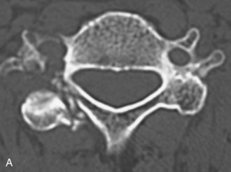
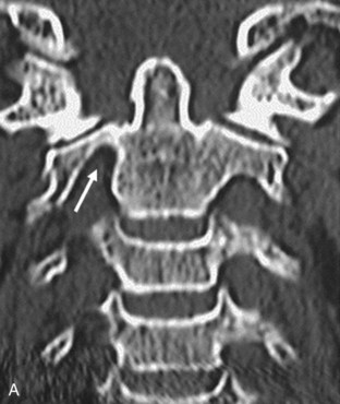
• Pedicles of the vertebra associated with major anomalies of the vertebral artery, and so forth, are inadequate and risky for screw insertion (Figures 13-1 and 13-2).
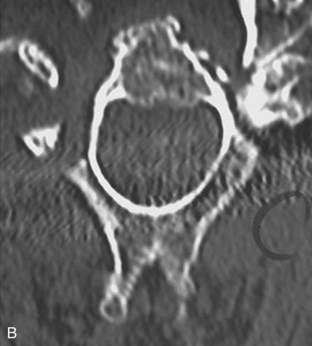
• Figure 13-1 shows an abnormal condition of the cervical pedicle. Pedicles destroyed by injuries, tumors, or marked osteoporosis; extremely small pedicles; pedicles of the vertebrae associated with major anomalies of the vertebral artery, and so forth, are inadequate and risky for screw insertion. Figure 13-1, A shows a fracture of the pedicle in a patient with a lateral mass fracture. Figure 13-2, B shows a pedicle of an extremely small size in a patient with rheumatoid arthritis.
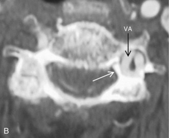
• Figure 13-2 shows a small size of the pedicle of the axis. Figure 13-2, A shows that the diameter of right side of the pedicle of the axis is too small for screw insertion by high-riding vertebral artery bends into the lateral mass of the axis (arrow). Figure 13-2, B shows extremely small pedicles of the axis for screw insertion.
• Patients sometimes have extreme unilateral dominance of the vertebral artery. In this condition, the dominant-side foramen transversarium enlarges, and the ipsilateral side of the pedicle decreases in size (Figure 13-3). Retrogression of the pedicle is found on the side of the dominant vertebral artery. Figure 13-3, A shows that patients sometimes show extreme right-left dominance of the vertebral artery. Figure 13-3, B shows that the dominant side of the foramen transversarium enlarges and that the ipsilateral side of the pedicle decreases in size (white arrow).
• For the patient with unilateral obstruction of the vertebral artery by injury, tumor, congenital anomaly, and so forth, screw insertion on the preserved artery side must be conducted with great care, or screw insertion should only be performed on the obstructed side.
Examination/Imaging
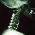
 Preoperative oblique-projection plain radiograph films are valuable for evaluation of the pedicle size. In an oblique projection, the contralateral pedicle is seen as an oval projected onto the vertebral body, showing the outer and inner diameter of the pedicle. If the projection shows no inner diameter, the pedicle does not have a medullary canal.


Surgical Anatomy
 According to previous studies by Panjabi and colleagues and by Karaikovic and colleagues, the pedicle of the cervical spine in a normal population has a sufficient diameter to allow insertion of a screw with a diameter of 3.5 mm or more.

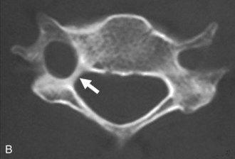
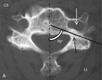
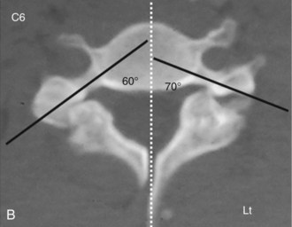
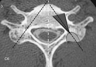
 Pedicle screw insertion into a vertebra with an extremely large angle between the pedicle axis and the sagittal plane may be possible but puts the vertebral artery and the spinal cord at risk. Figure 13-4 shows an extremely large angle between the pedicle axis and the sagittal plane. The left side of the foramen transversarium is enlarged toward the vertebral body (Figure 13-4, A, open arrow), and the angle between the pedicle axis (black line) and the sagittal plane is extremely large because of deformation of the foramen. In a case of C6 spondylolysis, the angle between the pedicle axis (Figure 13-4, B, black line) and the sagittal plane is extremely large. Screw insertion into the left side of the pedicle is too risky for the vertebral artery and the spinal cord.

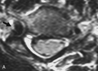
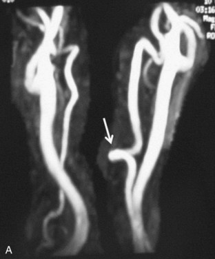
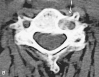
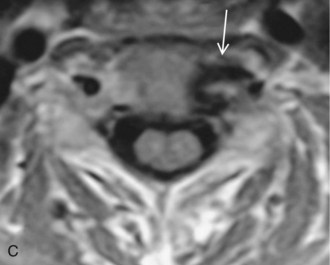
 The vertebral artery sometimes bends into the vertebral body forming the loop, and screw insertion into the ipsilateral side of the pedicle may put the artery at risk. Figure 13-5 shows loop formation of the vertebral artery.
 MRA shows the medial loop of the left vertebral artery (Figure 13-5, A, arrow).
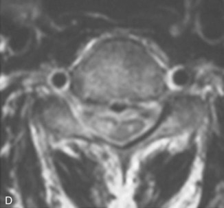
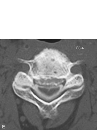
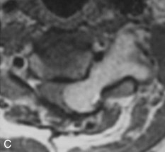
 CT (Figure 13-5, B) and MRI (Figure 13-5, C) images show that the vertebral artery bends into the vertebral body, forming the loop (arrows). Screw insertion into the left side of the pedicle is too risky for the artery.
Positioning
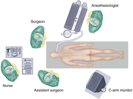
 The authors prefer to stand at the head of the patient, to ensure symmetric insertion of the right and left screws, while the assistant for a right-handed surgeon usually stands on the left side of the patient.
 The C-arm display is placed on the left side of the patient near the patient’s pelvis for easy viewing by the surgeon. The authors’ preferred operation room setup for posterior cervical spinal procedures is shown in Figure 13-6.


Portals/Exposures
 A skin incision is made, usually longer than that required for a standard spinous process wiring. The cephalad adjacent lamina of the most cephalad-fixed vertebra should entirely be exposed, taking care to protect the surrounding facet joint capsule. The paravertebral muscles are dissected laterally to expose the lateral margins of the articular masses for exact mediolateral determination of the screw insertion point.
Procedure
Step 1: Manual Screw Placement
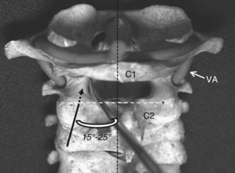
 The cranial margin of the C2 lamina is the craniocaudal landmark for the screw insertion point for C2. To confirm the screw insertion points in C2, a small spatula can be inserted into the spinal canal along the cranial margin of the C2 lamina to the medial surface of the C2 pedicle. Figure 13-7 shows the pedicle screw insertion point for C2. The cranial margin of the C2 lamina (white broken line) is the landmark for the screw insertion point for C2 (asterisk). To confirm the screw insertion points in C2, a small spatula can be inserted into the spinal canal along the margin cortex of the C2 pars interarticularis to the medial surface of the C2 pedicle. The black broken arrow indicates the screw direction toward the C2 pedicle.


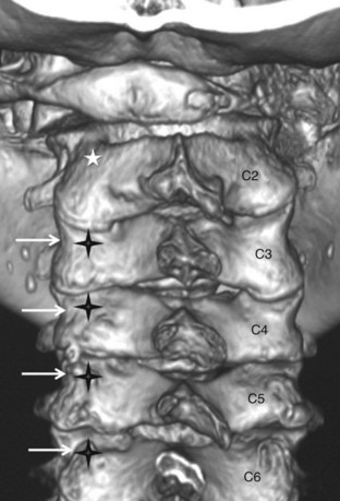
 The lateral margin of the articular mass of the cervical spine has a notch approximately at the level of the pedicle. The pedicles are located approximately below the lateral vertebral notch at C2, at the notch at C3 through C6, and at or slightly above the notch at C7. Figure 13-8 shows the pedicle screw insertion points for C3 to C7. Three-dimensional CT reconstruction shows the screw insertion points for C3 to C7. The lateral margin of the articular mass of the cervical spine has a notch approximately at the level of the pedicle (white arrow). The pedicles are located approximately below the lateral vertebral notch at C2, at C3 to C6, and at or slightly above the notch at C7. Screw insertion points (black crosses) are 2 to 4 mm medial to the notch. The white asterisk shows the C2 pedicle screw insertion point.


Computer-Assisted Screw Placement
 Modern technology for computer navigation systems has been developing in the field of cervical spine surgery.


Step 1 Instrumentation/Implantation
• Screw diameters vary from 3.5 to 4.5 mm for cervical pedicle screw fixation. However, a screw with a proper diameter must be chosen to obtain sufficient bite of the screw thread in the pedicle cortex. The length of the screw is usually 20 to 24 mm for C3 to C7. A screw length of 24 mm or more is sometimes required to penetrate the anterior cortex of the vertebral body to increase the C2 screw stability. A constrained type of locking mechanism is essential for connecting the screws and plates/rods, to obtain the rigid stabilizing effect of this procedure. Regarding the longitudinal connectors of screws, a rod rather than a plate is recommended for multisegmental fixation.
Step 2
 Before plate or rod application, a posterior decompression by laminoplasty or laminectomy is recommended for a patient with a narrow spinal canal, to avoid possible neurologic deterioration caused when the vertebral alignment is changed after longitudinal connection of the screws.

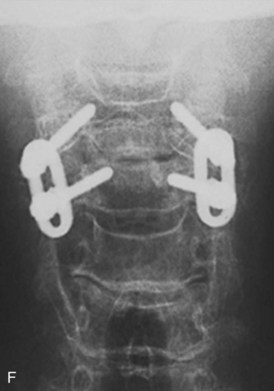
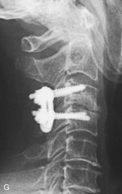
 In the final stage of instrumentation, inserted screws are connected with a plate or rod.

Step 3
• The pedicle screw procedure is a strong tool for correction of the deformities in the cervical spine.
• Plates and rods are contoured in the sagittal plane, with the expected correction of kyphotic deformity.
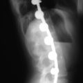
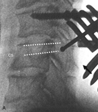
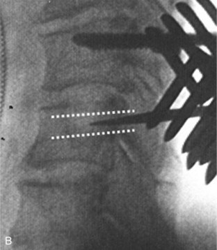
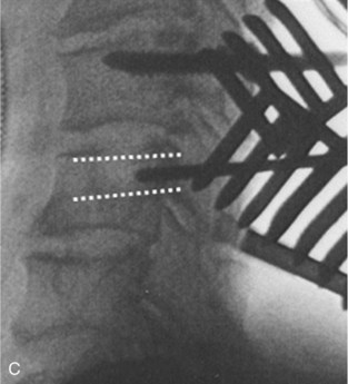
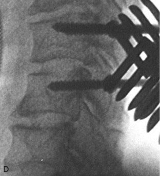
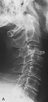
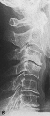
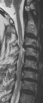
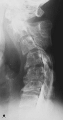
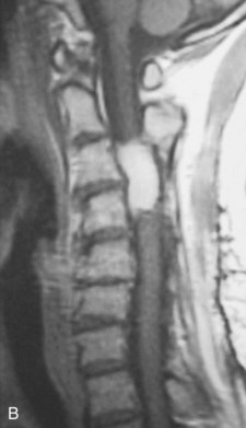
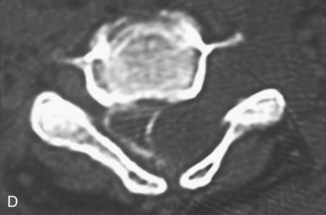
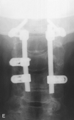
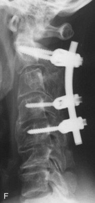
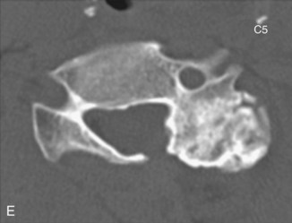
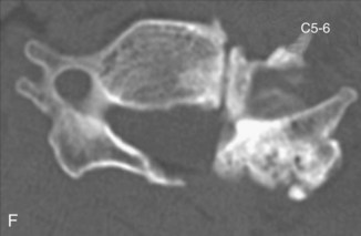
• Correction of the kyphosis is performed by tightening the nuts or by rotating the rods using rodholders (Figure 13-12). A preoperative myelogram (see Figure 13-12, A) shows postlaminectomy kyphosis. MRI images (see Figure 13-12, B and C) demonstrate dumbbell-type recurrent spinal cord tumor (schwannoma). A postmyelogram CT (see Figure 13-12, D) shows that the tumor is expanding from intracanal-extradural to the outside of the spinal canal. The patient sustained progressive spinal cord compression symptoms. The patient underwent simultaneous posterior decompression by tumor extirpation and correction of kyphosis (see Figure 13-12, E and F). Consequently, the posterior part of the cervical spine can be shortened.
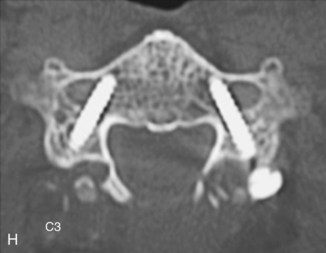
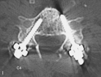
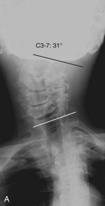
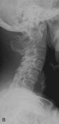
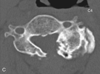
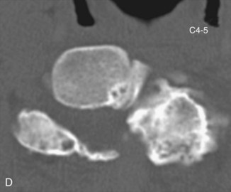
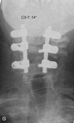
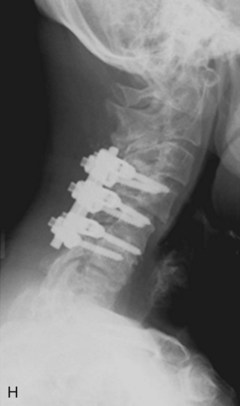
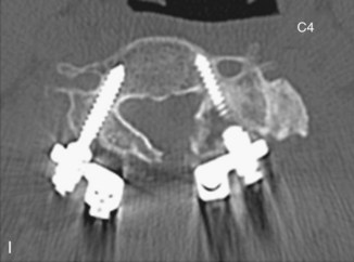
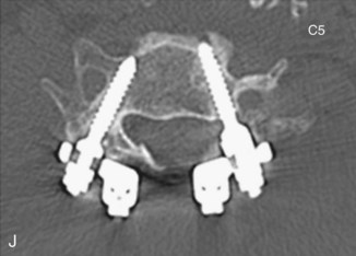
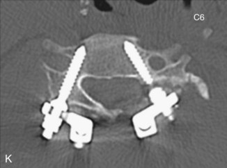
• Cases of cervical scoliosis requiring surgical correction are uncommon. If necessary, however, the deformity is correctable using this procedure by applying distraction force on the concave side (Figure 13-13). Preoperative images (see Figure 13-13, A and B) show 31 degrees of scoliosis after laminoplasty. The patient suffered from severe radiculopathy of the left C5 and C6 caused by C4-5 and C5-6 foraminal stenosis. Preoperative CT scans (see Figure 13-13, C to F) show proliferated degenerative changes of the left lateral mass. In Figure 13-13, G and H, postoperative images show sufficient correction of scoliosis. Postoperative CT images (see Figure 13-13, G to K) show proper screw placement in each vertebra.
Step 3 Pearls
• The neural foramina in patients with degenerative disorders are sometimes stenotic preoperatively. There is the risk of iatrogenic nerve root lesion because of foraminal stenosis caused by reduction of anterior translation or correction of kyphosis.
• Reconstructive CT performed in the oblique plane provides useful information about the size of the neural foramen.
• The use of a washer under the plate/rod for the cranial vertebral screws is helpful in situations where excessive reduction would occur during screw tightening.
• During the correction of kyphosis, the surgeon must also avoid applying excessive compression force at the spinal segment having neural foraminal stenosis because of degenerative changes. A prophylactic foraminotomy is recommended for the segments with marked stenosis of the neural foramen.
Postoperative Care and Expected Outcomes
 Complications directly attributable to screw insertion
 Complications not directly attributable to screw insertion
Summary
 Pedicle screw fixation is a strong procedure for reconstruction of the cervical spine in various types of disorders. Furthermore, a screw inserted into the cervical pedicle screw can be a strong anchor for reconstruction of the craniocervical junction and cervicothoracic spine. Surgeons must keep in mind that there must be limitations of cervical pedicle screw placement based on anatomic variations of the pedicle and vertebral artery. Complications associated with cervical pedicle screw fixation cannot be completely obviated; however, they can be minimized by sufficient preoperative imaging studies of the pedicles, thorough knowledge of local anatomy, and strict control of screw placement during surgery.

Abumi K, Ito M, Kotani Y. Complications of cervical pedicle screw placement. Semin Spine Surg. 2002;14:112-124.
Abumi K, Ito H, Taneichi H, et al. Transpedicular screw fixation for traumatic lesions of the middle and lower cervical spine. Description of the techniques and preliminary report. J Spinal Disorder. 1994;7:19-28.
Abumi K, Kaneda K, Shono Y, et al. One-stage posterior decompression and reconstruction of the cervical spine by using pedicle screw fixation systems. J Neurosurg. 1999;90(Suppl 1):19-26.
Abumi K, Shono Y, Ito M, et al. Complication of pedicle screw fixation in reconstructive surgery of the cervical spine. Spine. 2000;25:962-969.
Abumi K, Shono Y, Taneichi T, et al. Correction of cervical kyphosis using pedicle screw fixation systems. Spine. 1999;24:2389-2396.
Abumi K, Takada T, Shono Y, et al. Posterior occipitocervical reconstruction using cervical pedicle screws and plate-rod systems. Spine. 1999;24:1425-1434.
Duan S, Lv S, Ye F, Lin Q. Imaging anatomy and variation of vertebral artery and bone structure at craniocervical junction. Eur Spine J. 2009;18:1102-1108.
Dunlap BJ, Karaikovic EE, Park HS, Sokolowski MJ, Zhang LQ. Load-sharing properties of cervical pedicle screw-rod constructs versus lateral mass screw-rod constructs. Eur Spine J. 2010;19:803-808.
Goel A, Leheri V. Plate and screw fixation for atlanto-axial subluxation. Acta Neurochir (Wien). 1994;129:47-53.
Hojo Y, Ito M, Abumi K, et al. A late neurological complication following posterior correction surgery of severe cervical kyphosis. Eur Spine J. 2010;20:890-898.
Ishikawa Y, Kanemura T, Yoshida G, et al. Clinical accuracy of three-dimensional fluoroscopy-based computer-assisted cervical pedicle screw placement: a retrospective comparative study of conventional versus computer-assisted cervical pedicle screw placement. J Neurosurg Spine. 2010;13:606-611.
Johnston TL, Karaikovic EE, Lautenschlager EP, et al. Cervical pedicle screws vs. lateral mass screws: uniplanar fatigue analysis and residual pullout strengths. Spine J. 2006;6:667-672.
Karaikovic EE, Daubs MD, Madsen RW, et al. Morphologic characteristics of human cervical pedicles. Spine. 1997;22:493-550.
Karaikovic EE, Kunakornsawat S, Daubs MD, et al. Surgical anatomy of the cervical pedicles: landmarks for posterior cervical pedicle entrance localization. J Spinal Disord. 2000;13:63-72.
Karaikovic EE, Yngsakmongkol W, Gaines RW. Accuracy of cervical pedicle screw placement using the funnel technique. Spine. 2001;26:2456-2462.
Kast E, Mohr K, Richter HP, Borm W. Complication of transpedicular screw fixation in the cervical spine. Eur Spine J. 2005;15:327-334.
Kim HS, Heller JG, Hudgins PA, et al. The accuracy of computed tomography in assessing cervical pedicle screw placement. Spine. 2003;28:2441-2446.
Kotani Y, Abumi K, Ito M. Improved accuracy of computer-assisted cervical pedicle screw insertion. J Neurosurg. 1993;99(Suppl 3):257-263.
Kothe R, Ruther W, Schneider E, et al. Biomechanical analysis of transpedicular screw fixation in the subaxial cervical spine. Spine. 2004;29:1969-1975.
Leconte P. Fracture et luxation des deux premieres vertebres cervicales. In: Judet R, editor. Luxation Congénitale de la Hanche. Fractures du Cou-de-pied Rachis Cervical. Actualités de Chirurgie Orthopédique de l’Hôpital Raymond-Poincaré, vol 3. Paris: Masson et Cie; 1964:147-166.
Ludwig SC, Kowalski JM, Edwards CC2nd, et al. Comparative accuracy of two insertion techniques. Spine. 2000;25:2675-2681.
Oda I, Abumi K, Sell LC, et al. Biomechanical evaluation of five different occipito-atlanto-axial fixation techniques. Spine. 1999;24:2377-2382.