Procedure 25 Sacropelvic Fixation
Indications
 Long spinal fusion to the sacrum

 Degenerative spinal deformities
 Spondylolisthesis (high grade)


Indications Pitfalls
• Variable anatomy of the sacrum and pelvis may add challenge to the procedure.
• The sacrum has poor bone quality, mainly cancellous and often osteoporotic.
• The sacropelvis functions as a unit; this segment must transmit the full weight of the body from the spine to one or both femoral heads. It must do this in a static environment, such as sitting or standing, and in a dynamic environment, such as walking and running.
• Large loads going through this segment, creating cantilever pullout forces, are the primary reasons for construct failure.
Indications Controversies
• Long fusion has been described by some authors as four levels extending to L2, while others define a long fusion as one that crosses the thoracolumbar junction.
• The long lever arm generated by incorporating more segments into the fusion requires additional fixation points to achieve a rigid construct at the lumbosacral junction.
• High risk of pseudarthrosis (9% to 41%), instrumentation failure (3% to 44%), and loss of lumbar lordosis (20% to 49%) are associated with fusion down to the sacrum.
• Terminating a long fusion at L5 might lead to subsequent degeneration of the L5-S1 disk and might impact sagittal balance.
• Degeneration of the sacroiliac (SI) joint, although so far not clinically significant, might be a concern in patients with implants violating the sacroiliac articulation (iliac and S2AI screws).
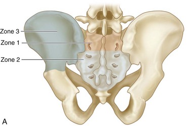
Biochemical Considerations
 The lumbosacral junction is a transition from a highly mobile segment to a stiff segment, resulting in great stress concentrations when the biomechanics of this segment are altered by instrumentation and fusion. Forces include axial loading of up to 3 times body weight in activities of daily living; substantial shear, especially with a more vertical S1 end-plate alignment; flexion/extension moments; and torsion.

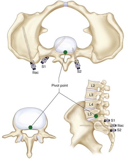
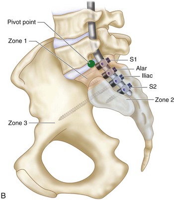
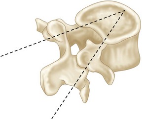
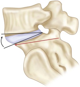
 Lumbosacral pivot point (McCord et al, 1992)


Examination/Imaging
 Pelvic obliquity and sacral inclination should be noted, especially in cerebral palsy patients.
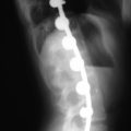
 Obtain spot lateral and true anteroposterior films of sacrum.


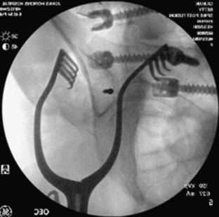
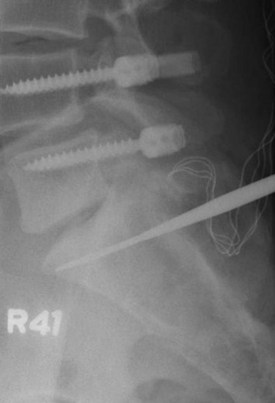
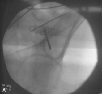
 Intraoperative teardrop view of the pelvis allows safe placement of iliac and sacroiliac screws in the bony canal between the posterior superior iliac spine (PSIS) and anterior inferior iliac spine (AIIS). Figure 25-4 shows an intraoperative radiograph showing a teardrop view with the guidewire within an all-osseous channel between the PSIS and AIIS.
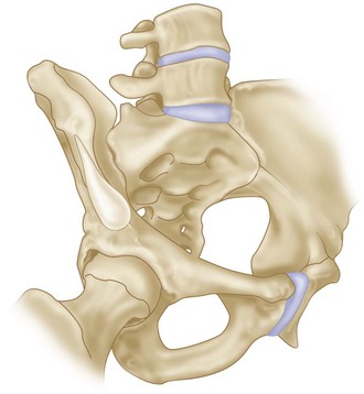
 An intraoperative teardrop view is obtained by a combined obturator oblique–outlet view, with an approximately compound 45-degree anterior and 45-degree cephalad angulation of the beam. Figure 25-5 is a schematic representation of the position of the pelvis while obtaining a teardrop view with superimposed shadows of the PSIS and AIIS and iliac rim above the sciatic notch.


Positioning
 Positioning is according to the procedure being done; the vast majority of patients are positioned prone. Lumbar lordosis is maintained by pads placed to support the chest, iliac crests, and thighs. The abdomen is left hanging free, decreasing intraabdominal pressure. This decreases epidural bleeding.


Procedure A: S1 Pedicle Screws
 S1 pedicular screws can either be placed unicortical, bicortical, or tricortical. S1 screws should always be supplemented by distal fixation or an interbody fusion, because they are rarely used alone for fusion to the pelvis.


Procedure a Pearls
• The tricortical technique provides three potential points of fixation.
• The technique allows the surgeon to place longer screws into the sacrum than either the unicortical or bicortical technique.
• This technique permits the standard medial angulation, thereby allowing triangulation of the pedicle screws in the coronal and sagittal plane, increasing screw pullout strength.
• Using the large pedicle finder (Figure 25-9) is preferred over a small one or a drill because it allows more medialization of the S1 screw and, therefore, better triangulation.
Procedure B: Sacral Alar Screws
 This typically involves unicortical fixation into the cancellous bone of the ala. The screws are directed laterally in the ala. The internal iliac vessels, lumbosacral trunk, and sacroiliac joints can be injured if these screws penetrate the anterior cortex. Alar screws are currently used by some as supplemental fixation.

Procedure B Pitfalls
• Sacral ala fixation is directed into low-density cancellous bone.
• Bicortical technique is not recommended, because the L5 nerve roots cross the sacral ala bilaterally, and the common iliac vessels are located directly on the anterior surface.
• Angulation of more than 20 degrees laterally puts the L5 root at risk for anterior cortex penetration.
• The L4 root is at risk as it crosses over the lateral one third of the anterior ala, with screw angulation more than 30 degrees laterally.
Procedure C: Iliosacral Screws
 Iliosacral screws are placed through the outer table of the ilium, through the SI joint, and into the lateral sacrum. This bone channel has been well described and is regularly used in pelvic trauma. The cortical purchase at the inner and outer tables of the ilium and the entrance point to the sacrum provides greater stability to pullout. Iliosacral screws have biomechanical advantage over S1 fixation and alar screw fixation, but the development of easier and safer techniques has made their use less common.
Procedure D: Galveston Rods
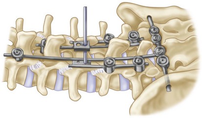
 In the 1980s, Allen and Ferguson (1982) introduced the Galveston technique to incorporate the ilium into the base of the fusion construct. Their instrumentation consisted of contoured smooth rods that were inserted from the posterior superior iliac spine, extending into each ilium between the inner and outer tables. The rods can be attached to the proximal levels by sublaminar wires and, more recently, by pedicle screws and hooks (Figure 25-13).

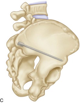
Procedure E: Iliac Screws (Iliac Bolts)
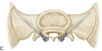
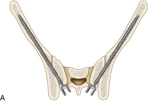
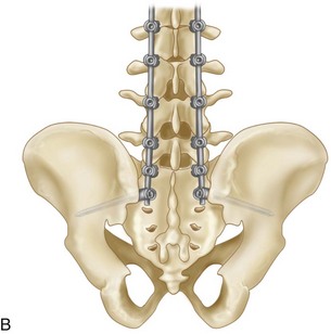
 Iliac screws were developed as an evolution of the Galveston technique. Iliac screws offer greater resistance to pullout secondary to the cancellous threads. Iliac screws may be partially or fully threaded and are connected to the longitudinal rods with special connectors. This is one of the most widely used techniques, when long fusions to the pelvis are performed. The modularity makes it possible to put more than one screw into the ilium, and screws can also be placed even in the face of a previous bone graft harvest. Figure 25-14 shows a schematic representation of lumbosacral fixation with S1 pedicular screws and two iliac screws.

Procedure E Pearls
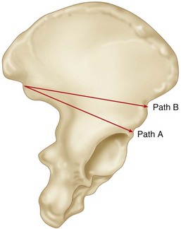
• The iliac screws should be long enough to end anterior to the pivot point, thus allowing the force acting on them to change from inline pullout to cantilever bending.
• Partial excision of the PSIS allows the head of the screws to lie deeper within the ilium, preventing prominence.
• Iliac screws are directed toward the cortical bone of the sciatic notch, which is the strongest in the ilium.
Procedure E Pitfalls
• Iliac screws require an additional incision for placement.
• The procedure may decrease the volume of autogenous bone graft.
• The procedure requires cumbersome offset connectors (Figure 25-17).
• The procedure may cause pain because of prominence.
• The procedure requires removal in 22% of the patients (Tsuchiya et al, 2006).
Procedure F: Transilial Bar
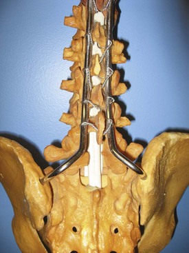
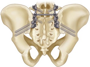
 In the 1960s, Harrington devised a sacral bar. At that time fixation to the bar was by hooks only, which did not control rotational stresses or flexion extension as well. Kostuik (1988) subsequently modified the Harrington sacral bar moments by using a transiliac bar fixed to S1 pedicle screws, to which proximal longitudinal members could be connected (Figure 25-18). Sacropelvic fixation using the transilial bar technique is an easy and effective method of achieving pelvic anchorage in long posterior spinal fusions but is not recommended without the use of anterior column support.

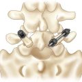
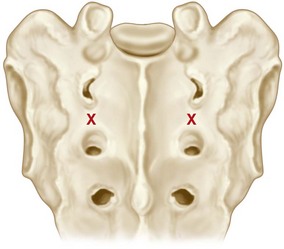
Procedure G: S2 Alar Iliac Screws (S2AI)
 Pelvic fixation using the S2 alar iliac technique was described by Kebaish (2010) and by Sponseller and colleagues (2010) in the adult and pediatric populations, respectively. Use of the S2 alar iliac technique may address some of the issues with spinopelvic fixation. S2AI screws do not require a separate fascial or skin incision or the use of offset connectors. Placement of S2AI screws does not interfere with iliac crest harvest, while allowing the use of longer screws than the iliac bolts allow. The solid pelvic anchor provided by the S2AI technique allows performing corrective procedures at the lumbosacral junction, such as S1 and L5 osteotomies, thus achieving more linear correction of the sagittal vertical axis, and hence better sagittal restoration of sagittal balance.
 Technique (authors’ preference)

Procedure G Pearls
• Insertion of S1 screws first will ensure a starting point that allows in-line rod placement.
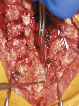
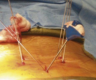
• Using the greater trochanter as a landmark allows safe placement without fluoroscopy in most patients. Figure 25-22 is an intraoperative view showing the direction of drilling of the S2AI screw toward the greater trochanter, which may be felt by the surgeon’s opposite hand.
• Tap drilling and ensuring there is a hard end point during advancement of the drill will prevent violation of the cortices of the ilium.
• Placing a guidewire after the initial drilling could minimize the use of a C-arm and guarantee a correct trajectory.
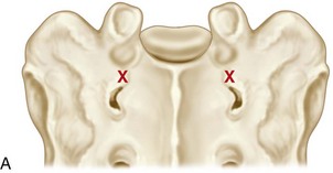
• A teardrop view will guarantee a correct trajectory in difficult pelvic anatomy (Figure 25-23, A).
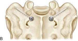
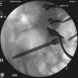
• Keeping the screw pathway just above the greater sciatic notch allows the biggest screw diameter (Figure 25-23, B)
• Partially burying the screw head to avoid prominence allows, on average, 15-mm deeper implants than with iliac screws.
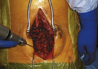
• S2AI screws can be placed percutaneously by a minimally invasive approach (Figure 25-24).
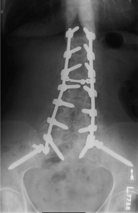
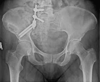
• Figure 25-25 shows postoperative radiography of double S2AI screws.
Postoperative Care and Expected Outcomes
Complications of Pelvic Fixation
 Misplacement and injuries to adjacent structures
 Implant prominence and loosening
 Wound complications and infection

Allen BLJr, Ferguson RL. The Galveston technique for L rod instrumentation of the scoliotic spine. Spine. 1982;7:276-284.
Berry JL, Stahurski T, Asher MA. Morphometry of the supra sciatic notch intrailiac implant anchor passage. Spine. 2001;26:E143-E148.
Bridwell KH, Edwards CC, Lenke LG. The pros and cons to saving the L5–S1 motion segment in a long scoliosis fusion construct. Spine. 2003;20:234-242.
Devlin VJ, Asher MA. Biomechanics and surgical principles of long fusions to the sacrum. Spine State Art Rev. 1996;10:515-544.
Farcy JP, Rawlins BA, Glassman SD. Technique and results of fixation to the sacrum with iliosacral screws. Spine. 1992;17(Suppl. 6):S190-S195.
Glazer PA, Colliou O, Lotz JC, et al. Biomechanical analysis of lumbosacral fixation. Spine. 1996;21:1211-1222.
Gokaslan ZL, Romsdahl MM, Kroll SS, et al. Total sacrectomy and Galveston L-rod reconstruction for malignant neoplasms. Technical note. J Neurosurg. 1997;87:781-787.
Harrington PR. Treatment of scoliosis: correction and internal fixation by spine instrumentation. J Bone Joint Surg Am. 1962;44:591-610.
Kebaish KM. Sacropelvic fixation techniques and complications. Spine. 2010;35:2245-2251.
Kim YJ, Bridwell KH, Lenke LG, Rhim S, Cheh G. Pseudarthrosis in long adult spinal deformity instrumentation and fusion to the sacrum: prevalence and risk factor analysis of 144 cases. Spine. 2006;20:2329-2336.
Kostuik JP. Treatment of scoliosis in the adult thoracolumbar spine with special reference to fusion to the sacrum. Orthop Clin North Am. 1988;19:371-381.
Kostuik JP, Musha Y. Extension to the sacrum of previous adolescent scoliosis fusions in adult life. Clin Orthop. 1999;364:53-60.
Lebwohl NH, Cunningham BW, Dmitriev A, et al. Biomechanical comparison of lumbosacral fixation techniques in a calf spine model. Spine. 2002;27:2312-2320.
Lehman JrRA, Kuklo TR, Belmont JrPJ, et al. Advantage of pedicle screw fixation directed into the apex of the sacral promontory over bicortical fixation: a biomechanical analysis. Spine (Phila Pa 1976). 2002;27:806-811.
Lemma M, Cohen DB, Riley 3rdLH, et al. Fusion to the sacrum: results of transiliac fixation. Spine J. 2002;2:3S-44.
McCord DH, Cunningham BW, Shono Y, et al. Biomechanical analysis of lumbosacral fixation. Spine (Phila Pa 1976). 1992;17:S235-S243.
Moshirfar A, Rand FF, Sponseller PD, et al. Pelvic fixation in spine surgery. Historical overview, indications, biomechanical relevance, and current techniques. J Bone Joint Surg Am. 2005;2(Suppl. 87):89-106.
O’Brien JR, Matteini L, Yu WD, Kebaish KM. Feasibility of minimally invasive sacropelvic fixation percutaneous S2 alar iliac fixation. Spine (Phila Pa 1976). 2010;35:460-464.
O’Brien MF, Kuklo TR, Lenke LG. Sacropelvic instrumentation: anatomic and biomechanical zones of fixation. Semin Spine Surg. 2004;16:76-90.
Ogilvie JW, Schendel M. Comparison of lumbosacral fixation devices. Clin Orthop Relat Res. 1986;203:120-125.
Peelle MW, Lenke LG, Bridwell KH. Comparison of pelvic fixation techniques in neuromuscular spinal deformity correction: Galveston rod versus iliac and lumbosacral screws. Spine. 2006;31:2392-2398.
Ruland CM, McAfee PC, Warden KE, Cunningham BW. Triangulation of pedicular instrumentation: a biomechanical analysis. Spine. 1991;16:S270-S276.
Santos ERG, Rosner MK, Perra JH, Polly DW. Spinopelvic fixation in deformity: a review. Neurosurg Clin N Am. 2007;18:373-384.
Schildhauer TA, McCulloch P, Chapman JR, Mann FA. Anatomic and radiographic considerations for placement of transiliac screws in lumbopelvic fixations. J Spinal Disord Tech. 2002;15:199-205.
Shirado O, Zdeblick TA, McAfee PC, et al. Biomechanical evaluation of methods of posterior stabilization of the spine and posterior lumbar interbody arthrodesis for lumbosacral isthmic spondylolisthesis. J Bone Joint Surg Am. 1991;73:518-526.
Smith SA, Abibto JJ, Carlson GD, Anderson DR, Taggart KW. The effects of depth of penetration, screw orientation, and bone density on sacral screw fixation. Spine. 1993;18:1006-1010.
Sponseller PD, Zimmerman RM, Ko PS, et al. Low profile pelvic fixation with the sacral alar iliac technique in the pediatric population improves results at two-year minimum follow-up. Spine (Phila Pa 1976). 2010;35:1887-1892.
Tsuchiya K, Bridwell KH, Kuklo TR, et al. Minimum 5-year analysis of L5–S1 fusion using sacropelvic fixation (bilateral S1 and iliac screws) for spinal deformity. Spine (Phila Pa 1976). 2006;31:303-308.