[level-membership-for-surgery-category]
Procedure 21 VEPTR Opening Wedge Thoracostomy for Congenital Spinal Deformities
Indications
 The titanium rib, or VEPTR (vertical expandable prosthetic titanium rib), is approved by the U.S. Food and Drug Administration (FDA) and is available for use under the Humanitarian Device Exemption regulations. One approved use is for constrictive chest wall disorders, including fused ribs and scoliosis.
 Progressive thoracic congenital scoliosis in patients age 6 months to skeletal maturity
 Three or more fused ribs at the apex of the concave hemithorax
 Greater than 10% reduction in space available for lung (Campbell et al, 2004)
 Presence of progressive thoracic insufficiency syndrome (Campbell et al, 2004)
Examination/Imaging
 Patients are evaluated for curve flexibility, head decompensation, truncal decompensation, and trunk rotation.

 Thoracic function resulting from chest wall expansion is assessed by the thumb excursion test (Campbell et al, 2004).
 The examiner’s hands are lightly placed on each side of the patient, around the lateral base of the thorax, with the thumbs in back pointing upward medially, equidistant from the spine (Figure 21-1). The patient breathes spontaneously, and rib cage motion carries the thumbs outward away from the spine. Greater than 1 cm of thumb motion away from the spine is normal and is graded as a +3 thumb excursion test; 0.5 to 1 cm is a +2 thumb excursion test; less than 0.5 cm motion is +1; and no thumb excursion with respiration is graded +0.

 Radiographs should include anteroposterior (AP) and lateral films of the entire spine, including the entire rib cage and the pelvis. These are assessed for Cobb angle, space available for the lungs, and head and truncal decompensation (Figure 21-2). Space available for the lungs is determined by the ratio of the height of the concave lung from the middle of the most proximal rib to the top of the hemidiaphragm compared with the height of the convex lung measured in the same fashion. Head decompensation is measured from the center sacral line to the middle of C7, and truncal decompensation is measured from the midthorax at T6 to the center sacral line.
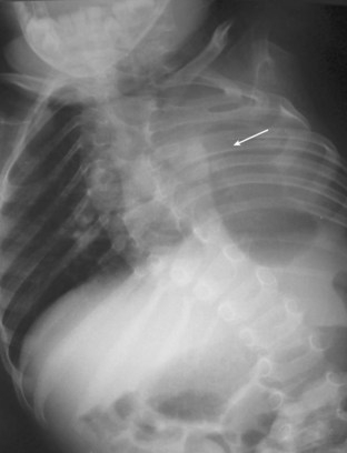
 Supine lateral bending radiographs are used to determine curve flexibility and apex of rib cage constriction on the concave side of the curve (Figure 21-3, arrow). In cases of thoracic kyphosis, a cross-table lateral radiograph of the spine with a bolster at the apex of the curve is included to assess for flexibility.

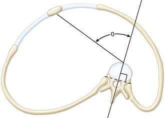
 Computed tomography (CT) scans of the chest and spine are performed, unenhanced, at 0.5-cm intervals from T1 to the sacrum, to assess for three-dimensional spine and rib cage abnormality. Thoracic rotation from rotation of the spine into the convex hemithorax with loss of lung volume is the angle between the sagittal plane of the spine and the sternum (Figure 21-4). To minimize radiation exposure, the scan should be performed at pediatric settings, with appropriate milliamperage and pitch angle.

 MRI of the entire spinal cord is performed to assess for spinal cord abnormalities.
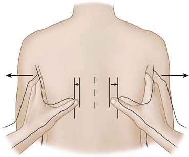
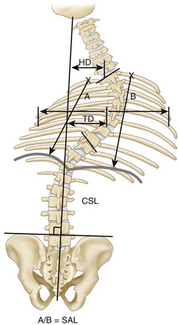
FIGURE 21-2 CSL, Centrosacral line; HD, head decompensation; SAL, space available for lung; TD, trunk decompensation.
Examination Pitfalls
• Progressive thoracic insufficiency syndrome, the prime FDA indication for VEPTR treatment, is difficult to define by standard radiographic assessment, because it is a dynamic condition. Thoracic insufficiency syndrome is the inability of the thorax to support normal respiration or lung growth (Campbell et al, 2004), and the presence of either component enables the diagnosis of TIS. The disabled thorax, such as seen in a child with fused ribs, cannot expand the lung with chest wall motion on the involved side; so, normal biomechanical respiration is not possible. The same thorax, if unable to grow properly because of the rib cage constriction due to rib fusion, also has the second component of TIS.
• TIS does not mean a child requires oxygen support. Pediatric patients needing oxygen, continuous positive airway pressure, or ventilator support have respiratory insufficiency, which means the respiratory mechanism is unable to provide physiologic oxygenation for the needs of the patient. Respiratory insufficiency may be due to intrinsic disease of the lungs and/or severe thoracic disability from volume depletion deformity (Campbell et al, 2003a) or abnormal thoracic function. Occult respiratory insufficiency syndrome in children with early TIS may be masked by an increase in respiratory rate, or adaptive behavior through reduction in activity levels for age. End-stage TIS almost always has associated respiratory insufficiency syndrome.
Controversies
• Patients with TIS and congenital scoliosis who are almost at the age of skeletal maturity: If thoracic height is near normal and thoracic volume and function adequate, then the growth-sparing aspect of VEPTR treatment on the spine deformity will have marginal impact on lung growth; so, definitive spine fusion is preferable.
• Isolated hemivertebra of thoracolumbar congenital scoliosis with limited rib fusion: If the thoracic spine is near normal height for age and treatment with hemivertebrectomy or hemiarthrodesis/hemiepiphyseodesis would involve three segments or less, then these techniques are preferable to VEPTR treatment.
• Mobile chest wall on the concave side of the curve: Although invariably the chest wall on the concave side of the curve is stiff from rib fusion, and the potential for VEPTR treatment to stiffen the concave chest wall is thus a moot point, then if the thumb excursion test does show mobility with normal outward motion of the concave chest wall during respiration, a growth-sparing treatment other than VEPTR should be considered.
Treatment Options
• Limited (one or two spinal segment[s]) hemivertebrectomy or convex hemiarthrodesis/hemiepiphyseodesis for isolated hemivertebra when the thoracic spine is of relatively normal length and the chest wall is mobile
• Growing rod instrumentation of the spine when the congenital spine deformity is more extensive and the chest wall is mobile on the concave side of the curve
• Posterior spine fusion for patients approaching skeletal maturity, when expansion of the chest will have no effect on growth of the underlying lungs
Surgical Anatomy
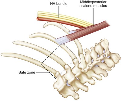
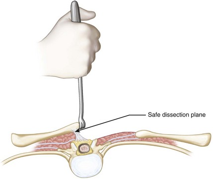
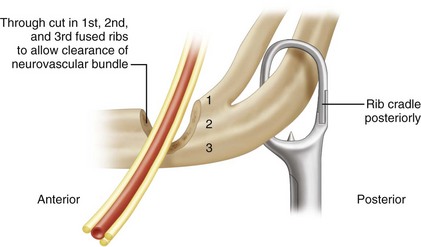
 Proximally, the common insertion of the middle and the posterior scalene muscle on the first and second ribs is identified. The brachial plexus and the artery lie immediately anterior to this (Figure 21-5). It is an important landmark, because the neurovascular bundle is just anterior. The safe zone for VEPTR proximal rib cradle attachment is posterior to the scalene muscles, extending from the second through the fourth ribs. Attachment anterior to the scalene muscles or posterior on the first rib endangers the neurovascular bundle.
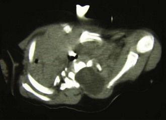
 Absent ribs in the exposure are identified by palpating the flail area. These are commonly associated with dysraphism of the spine, and care should be taken to avoid violating the spinal canal in the dissection. The preoperative CT scan commonly identifies bony defects in the canal. Figure 21-6 shows the CT scan of an infant with a spinal dysraphism with the meningocele extending up to the medial border of the scapula that was poorly appreciated on radiographs. In surgery, the scapula was gently retracted upward and the rhomboid muscles dissected just adjacent to the edge of the scapula so that the dura was not injured.
Positioning
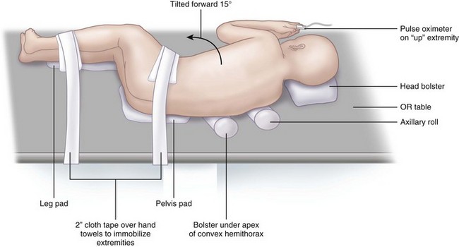
 The patient is placed in a modified lateral decubitus position with the torso tilted slightly forward (15 degrees) (Figure 21-7).


Positioning Pearls
• An axillary roll is used as well as a pad under the pelvis and the lower extremities. A soft bolster pad is placed under the apex of the thoracic deformity to help provide correction.
• A pulse oximeter is placed on the upward hand to monitor vascularity of the upper extremity. Both upper and lower extremities are monitored for spinal cord function with somatosensory evoked potentials and transcranial motor evoked potentials.
Portals/Exposures
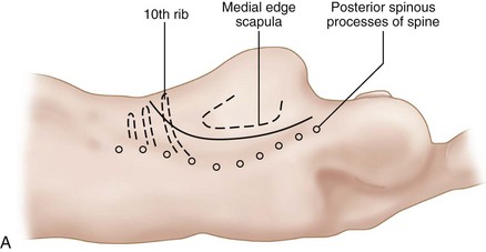
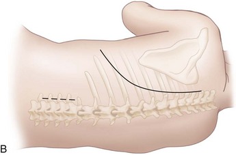
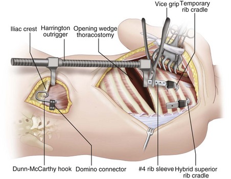
 To avoid skin slough, a long curvilinear incision is made, beginning proximally between the posterior spinous process of the spine at T1 and the medial edge of the scapula, extending distally down to the tenth rib, then anteriorly in a gentle curve along the rib to the posterior axillary line (Figure 21-8).

 The scapula is gently retracted laterally.


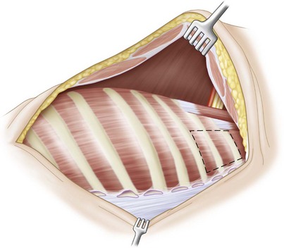
 The paraspinal muscles are reflected by cautery, laterally to medially, up to the tips of the transverse spinous processes, leaving a 1-mm thick layer of soft tissue overlying the ribs to avoid rib devascularization (Figure 21-9). The spine is not uncovered in order to avoid inadvertent fusion.
Positioning Pearls
• In congenital deformity of the thorax and spine, commonly the anatomy is significantly distorted with rib fusion and anomalous muscle insertion. The scalene muscles, however, are consistently present and, although anomalous in appearance, can often be palpated readily, thus providing a landmark for identification of the neurovascular bundle anteriorly.
• For purposes of identifying correct rib levels for insertion of devices, the first rib can usually be palpated posteriorly between the common insertion of the scalene muscles and the tips of the transverse processes, and levels then are counted distally through palpation.
Positioning Pitfalls
• Care should be taken to avoid damaging the spinal cord in areas of dysraphic spine adjacent to rib absence.
• In the Sprengel deformity, associated with fused ribs and scoliosis, there is commonly a fibrous or bony connection between the spine and the upwardly displaced hypoplastic scapula, but if there is dysraphism, the medial edge of the scapula may actually be inside the spinal canal, adjacent to the spinal cord. In this anatomic variant, a regular thoracotomy approach may injure the spinal cord when the rhomboid muscles are released medially; so, in these cases, the scapula is gently retracted upward out of the canal by a small rake and the medial muscles carefully stripped off the scapula above the canal, with care taken not to violate the dura to avoid spinal cord injury (Figure 21-10). A preoperative CT scan can define this variant.
Instrumentation
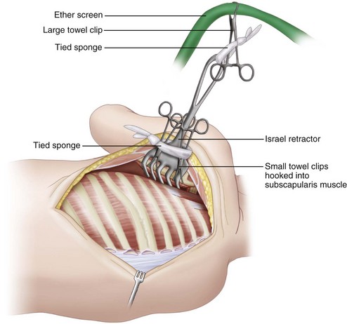
• It is helpful to retract the scapula with an Israel retractor placed under the scapula, with two small towel clips clamped under the muscle tissue in the manner of M.D. Smith. The clips are then attached by Ray-Tec sponges around the larger retractor. The Israel retractor is then attached by a Ray-Tec sponge to a large towel clip attached to an ether screen bar at the head of the operating table (Figure 21-11). This provides excellent self-retraction.
Procedure
Step 1: Insertion of Superior Rib Cradle for the Hybrid VEPTR
 After exposure is completed, the level of the insertion of the superior rib cradle is located. This is based on radiographic evidence and confirmed by locating the first rib by palpation and counting ribs downward. The superior cradle should be placed at the proximal end of the rib cage constriction, which is commonly proximal to the apex of the congenital spinal curve. The site is marked by cautery, just lateral to the tips of the transverse processes.


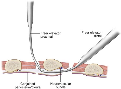
 A curved Freer elevator is then inserted through an intercostal incision into the inferior portal, pointed proximally, and is used to strip away the combined pleura/periosteum from the anterior surface of the rib, carefully creating a soft tissue tunnel up to the superior portal without damaging the neurovascular bundle. Next, a second Freer elevator is inserted into the superior portal and touched to the tip of the inferior Freer elevator in order to verify that a continuous soft tissue tunnel has been developed (Figure 21-12).

Step 1 Controversies
• The long, sweeping distal thoracotomy incision is performed for two reasons: A long thoracotomy flap is easier to stretch for closure after opening wedge thoracostomy and, in females, a more distal flap avoids cutting across breast tissue, which reduces risk of later breast growth disturbance in adolescents.
• If, after placement of the superior cradle, the rib(s) of attachment are found to be too weak for effective distraction, then the superior cradle should be reinserted around a stable rib more distally.
Step 1 Pearls
• If the site of attachment chosen for the superior cradle is a thin rib, then two ribs can be encircled to increase strength of attachment, using an extended cradle cap.
• If there is considerable kyphosis of the proximal rib cage, consider using VEPTR II, with multiple rib cradle attachment points extending up to the second rib and a long proximal rod extension of the rib sleeve contoured in gentle kyphosis to fit the bony deformity.
• If the ribs of attachment are somewhat mobile, the site of attachment can be moved medially to encompass 5 mm of the transverse processes for increased strength.
• If either the superior or inferior attachment point of the rib cradle is within a sheet of solid bone of fused ribs, then a channel for insertion of the superior cradle, 5 mm by 1.5 cm, can be cut with a power burr, adjacent to the transverse process tip.
Step 1 Pitfalls
• Take care not to insert the rib cradle above the thoracic constriction in a mobile proximal segment of spine. The distraction force of the VEPTR will overcorrect the proximal thoracic spine into a compensatory curve, without effect on either the primary thoracic constriction or the congenital scoliosis.
Instrumentation/Implantation
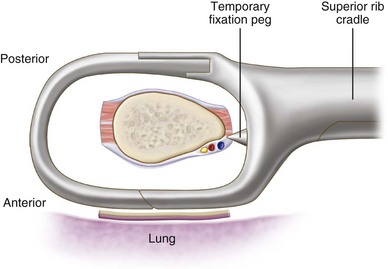
• The superior cradle cap is inserted by forceps into the superior portal, deep between the ribs, facing laterally to avoid the esophagus and the great vessels, and is then rotated downward into position.
• Next, the superior cradle is inserted into the inferior portal deeply, with the temporary fixation pegs anterior to the rib to hold the device in low profile (Figure 21-13). The superior cap is mated to the superior cradle, and the cradle cap lock is used to lock the two together.
• If there is an inability to completely engage the rib cap into the rib cradle because of soft tissue, then spinal compression forceps are used to compress the superior cradle and the cradle cap together, and a cradle cap lock is added.
• The forceps attached to the cradle cap are removed, and the forceps attached to the rib cradle are used to gently move it upward to verify stability.
Step 2: Opening Wedge Thoracostomy
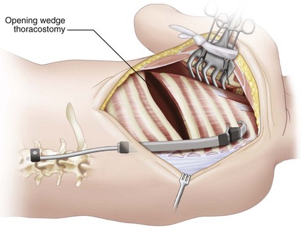
 The opening wedge thoracostomy is then performed at the center of the thoracic constriction. This is identified on plain AP radiographs, especially on the bending films, where there is an area of frank constriction of fused ribs or narrowed intercostal spaces.


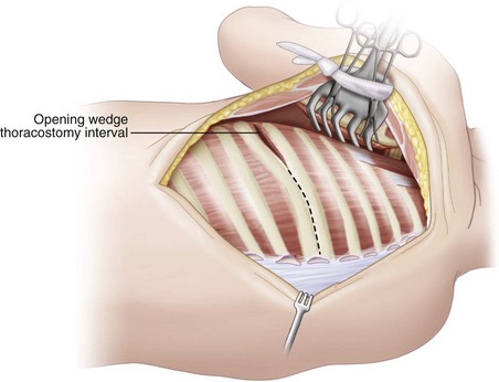
 The opening wedge thoracostomy is begun anteriorly where the ribs begin to separate, where there is usually fibrous tissue or an intercostal muscle interval that gradually narrows to a groove in the fused bone posteriorly (Figure 21-14).

 The thoracostomy should also extend anteriorly to the costochondral junction.

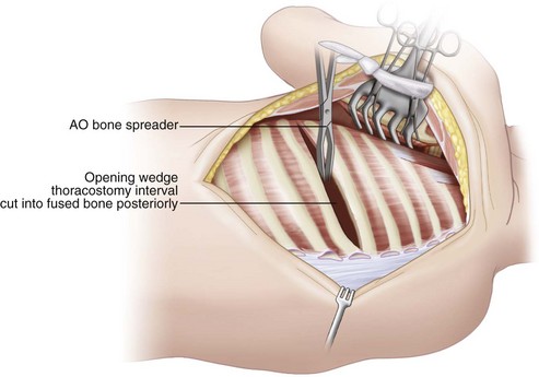
 Once the thoracostomy interval through bone, fibrous tissue, or intercostal muscle is complete, an AO bone spreader is inserted between the ribs to gradually widen the thoracostomy interval, with lengthening of the concave hemithorax and indirect correction of the scoliosis (Figure 21-15).


Step 2 Pearls
• The superior cradle is tilted medially at insertion because of the oblique position of the rib of attachment, but with successful hemithorax deformity correction through thoracostomy, it gradually assumes a position parallel to the longitudinal axis of the body, with transverse orientation of its rib of attachment.
• If the area of rib fusion on the concave side of the curve is greater than four ribs, a second, or even third, thoracostomy must be performed to completely correct the deformity, with at least two rib thicknesses between thoracostomies.
• It is important to use a soft tissue–sparing technique in performing the thoracostomy and inserting rib cradles. Stripping the periosteum over the ribs to facilitate exposure may devascularize the ribs and result in later absorption.
• Small rents in the pleura (less than 2 cm) are not serious and do not need repair. Larger tears are patched with Surgisis (Cook, Bloomington, Ind.) bioabsorbable membrane.
• Chest tubes are usually placed only if there is a “leak” from a visceral pleural tear of the lung or large quantities of pleural fluid are expected postoperatively.
• If the gap of the opening wedge thoracostomy needed to correct the constricted hemithorax is greater than 3 to 4 cm in width, the patient may develop a clinically flail chest. This is addressed by a centralization transport procedure (Campbell et al, 2004) in which a section of two fused ribs, either above or below the opening wedge thoracostomy, is osteotomized free through a second opening wedge thoracostomy and rotated centrally. With the large gap of the first opening wedge thoracostomy stabilized by the centralization transport, the risk of clinical flail chest is minimized.
• Alternatively, additional rib-to-rib VEPTRs may also be added anterolaterally to stabilize the flail area of the chest wall. These devices should not extend more proximal than the third rib because of proximity of the brachial plexus.
Step 2 Controversies
• The goal of VEPTR opening wedge thoracostomy is to create a lengthened hemithorax while indirectly correcting the scoliosis without spine fusion so that the thoracic spine can continue to grow and contribute to thoracic volume increase. There is no need to perform concurrent spine osteotomies, hemivertebrectomies, or convex hemiarthrodesis/hemiepiphyseodesis during VEPTR procedures. Unilateral segmented bars of the concave side of the curve increase in length, presumably from growth, with VEPTR treatment with effective growth of the thoracic spine (Campbell et al, 2003b). There is also risk of spine avulsion and severe neurologic injury if spine procedures are performed along with opening wedge thoracostomy because of the distraction power of the VEPTR device.
Step 3: The Hybrid VEPTR
 Once the proximal exposure for the hybrid VEPTR is complete, a lumbar spinal exposure is made distally to place a spinal hook for the hybrid VEPTR lumbar extension (see Figure 21-8, B).


Step 3 Pitfalls
• Take care not to damage the cortex of the inferior lamina where the hook is to be placed. Once the cortex is violated, it becomes weakened. Partial laminotomies of the inferior lamina are also to be avoided for the same reason.
• Insert a no. 4 Penfield elevator distally between the dura and the lamina to free up any scarring so that there is clearance for the hook.
Step 4: Implantation of the Hybrid VEPTR
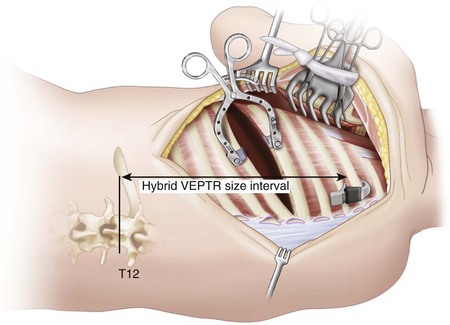
 The correct size of hybrid VEPTR device needed for implantation is determined by measuring the distance from the inferior part of the rib, attached to the superior rib cradle, to the inferior end plate of T12. The location of T12 can be estimated clinically by palpating the twelfth rib. This distance, in centimeters, will correspond to numbers inscribed on the VEPTR rib sleeve and lumbar hybrid extension (Figure 21-16).

 The rod is cut, and the lumbar hybrid extension bent into mild lordosis and valgus to fit.


Step 4 Instrumentation/Implantation
• Once the device is in place, the chest tube is removed, and the hybrid rod is threaded into the hook, and then the rib sleeve is threaded into the superior cradle and locked with a distraction lock.
• The C-clamp is attached to the rod, the rod is distracted, the hook is tightened, and the clamp removed.
• When the rib distractor is then removed, the opening wedge thoracostomy should remain open from the distraction of the hybrid VEPTR if the device is properly tensioned (Figure 21-17).
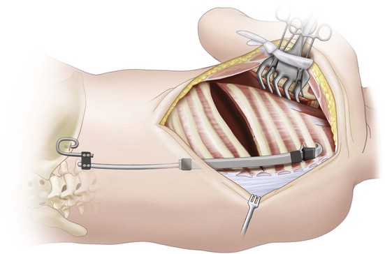
Step 5: Hybrid VEPTR Attachment to Pelvis by Dunn-McCarthy Hook over Iliac Crest
 If there are inadequate posterior elements of the posterior spine for attachment of the VEPTR hybrid spine hook, such as in myelomeningocele or dysraphism in congenital scoliosis, distraction is achieved by bypassing the spine and attaching the VEPTR hybrid lumbar extension rod to the iliac crest through a Dunn-McCarthy hook placed on top of the iliac crest.

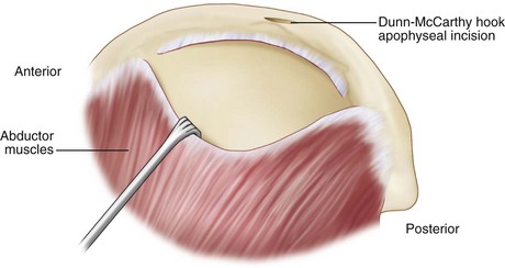
 Using cautery, the hip abductors are released over the bony part of the iliac crest just below the apophysis and reflected laterally with a Cobb elevator to create a pocket for the outer portion of the Dunn-McCarthy hook within the central third of the iliac crest (Figure 21-18).
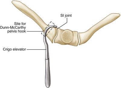
 A transverse incision is made in the middle of the apophysis with equal amounts of cartilage above and below. The interval is widened with Crigo elevators, and a tract is created over the anterior cortex of the iliac crest. The sacroiliac joint should be just medial to the tract. This is confirmed by placing a Crigo elevator through the apophyseal incision of the crest and then shifting the instrument to touch the lateral edge of the sacroiliac joint (Figure 21-19). The Dunn-McCarthy hook is then inserted through the incision.

Step 5 Pearls
• There is a flattened transition zone in the middle of the iliac crest before it tilts posteriorly. Place the 90-degree hook within this flattened zone.
• If there is severe pelvic obliquity with thoracolumbar or lumbar scoliosis, then correction can be gained by use of a Harrington outrigger to distract the pelvis away from the thorax.
Step 5 Pitfalls
• Placing a Dunn-McCarthy hook too far posteriorly will lead to eventual dislodgement of the hook, with migration posteriorly and inferiorly down the iliac crest. The correct position can be verified clinically by pushing the Crigo retractor through the apophyseal incision and moving it against the sacroiliac joint medially.
Step 5 Instrumentation
• After the Dunn-McCarthy hook is inserted, a 5- to 6-mm step-down domino coupling is placed over the hook with the 6-mm opening medial.
• A soft tissue channel from the proximal chest incision to the pelvic incision is made by a clamp and the chest tube is brought into the proximal wound.
• The lumbar hybrid extension and rib sleeve are sized to extend down to the bottom of T12. The rod is cut long enough to overlap the end of the Dunn-McCarthy hook by 2 cm and bent into mild lordosis. No valgus bending is necessary, because the pelvis hook is directly in line with the proximal site of attachment of the device.
• The assembled rib sleeve, and lumbar hybrid extension, with distraction lock are threaded by the chest tube into the pelvic incision.
• The lumbar extension is first passed into the domino, then mated with the superior cradle, and locked to the superior cradle with the distraction lock.
• The device is distracted through the rod end, and the domino is tightened (Figure 21-21).
Step 5 Controversies
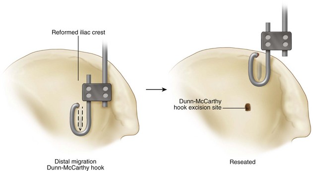
• The Dunn-McCarthy hooks will gradually migrate distally into the pelvis with time. This is generally not symptomatic, and they can migrate several centimeters into the crest without harm. The hook may require revision if symptomatic, or if the tip of the hook is within 5 mm of the acetabulum.
Step 6: Addition of Second Rib-to-Rib VEPTR
 A second VEPTR, a rib-to-rib construct, is next placed in the posterior axillary line to aid the hybrid device in deformity correction. The rib-to-rib VEPTR is placed laterally to the hybrid device, either parallel to it or slightly tilted toward it to avoid distal lateral migration (Figure 21-23).


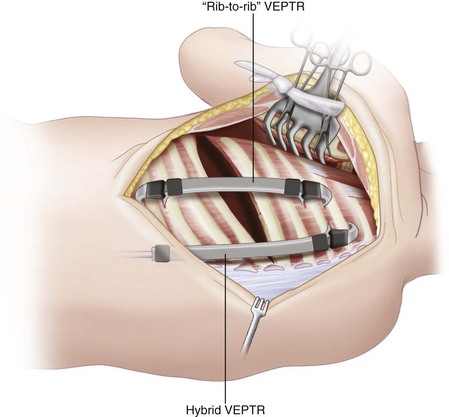
Step 6 Pearls
• Orient the second device parallel to the hybrid, veering somewhat medially, in order for the device to be perpendicular to the inferior rib of attachment.
• Using a soft tissue–sparing technique, maintaining intercostal muscle medial and lateral to the device will minimize the risk of the device sliding laterally down the rib.
• When the device is somewhat high profile, a temporary 0 Prolene suture can be used to pull it closer to the rib cage, where healing will stabilize it in a low-profile position.
Step 6 Instrumentation
• With the superior cradle in place, the correctly sized rib cradle with the rib sleeve is then placed over the inferior rib of attachment and mated to the superior cradle.
• With forceps, the device is gently maneuvered into place, and then locked superiorly with a distraction lock. The device is then expanded 0.5 cm, and a second distraction lock is added distally.
• The rib distractor is then removed.
• No. 7 and no. 10 Jackson-Pratt drains are placed beneath the muscle flaps.
Step 6 Controversies
• Do not use the expandable nature of the device to adjust for correct size. The measured interval should match the number designated on both the VEPTR rib sleeve and the inferior cradle/hybrid lumbar extension used.
• For children less 18 months old, with inadequate spinal canal to accept a hook, a hybrid VEPTR generally should not be used. A sole VEPTR rib-to-rib construct is used instead. Once the child is older than 18 months, then the rib-to-rib construct can be replaced with a hybrid, if desired.
Step 7: Closure
 The paraspinous muscles are placed back laterally over the medial device.


 No spine braces are used because of concern regarding their constrictive effect on the chest.
Step 7 Pearls
• To aid closure, the combined skin and muscle flaps are grasped with dry laparotomy sponges and then stretched toward the middle of the exposure. This is usually adequate to enable overlap of the skin edges.
• If desired, a catheter for infusion of local anesthesia can be placed under the flaps.
• If there is a pleural rent greater than 3 to 4 cm, this can be patched with a bioabsorbable membrane, such as Surgisis, sutured with absorbable sutures around the periphery of the pleura.
• To gain further closure, it is useful to undermine the muscle layers by cautery in both the superior and inferior flaps.
• If during closure signs of acute thoracic outlet syndrome are seen upon decreased signal on the pulse oximeter as well as change in the upper extremity spinal cord monitoring, then closure is relaxed. Tracings and pulse oximeter signals usually return to normal.
• Persistent loss of somatosensory evoked potentials tracings/pulse oximeter signal, indicating significant brachial plexus compression with elevation of the fused first and second ribs, may require acute partial resection of the first and second rib under the brachial plexus to relieve the obstruction if relaxation of distraction does not improve the findings. A trough in the fused ribs can be cut lateral to the rib cradle to allow passage of the neurovascular bundle without weakening the construct (Figure 21-24). This can be done through the thoracotomy incision, but also can be accomplished later through an axillary approach.
Step 7 Pitfalls
• It is important during closure to place as much muscle tissue as possible over the devices.
• Areas where there is muscle deficiency may be addressed by rotating flaps of muscle medially or laterally to help cover devices.
• Skin slough is most likely over the inferior portion of the lateral device and should be well covered with muscle.
Step 7 Controversies
• Chest tubes are seldom needed unless the visceral lung pleura is violated. If there is a significant “leak” in the lung, then a no. 20 chest tube is also inserted in addition to the two Jackson-Pratt drains.
• Steri-Strips are placed over the wounds, and a soft dressing is applied over the incisions. Surgical polyurethane foam is also added over the dressings to help pad the incisions and avoid skin slough.
Postoperative Care and Expected Outcomes
 Patients are kept in the intensive care unit for observation for approximately 3 to 5 days.
 Extubation is usually possible 48 to 72 hours after surgery.
 Pain control is addressed with intravenous morphine and oral codeine.
 Subcutaneous catheters for local anesthesia are usually removed in 48 hours.
 Chest radiographs are taken on a daily basis for 3 to 4 days.


 Chest tubes are removed when drainage has decreased to 1 mL/kg/day.


 Expected outcomes of treatment of fused ribs and congenital scoliosis include an average reduction in curvature of 25 degrees, improvement in the space available for the lungs to an average of 80% (Campbell et al, 2003b), and an average 7% increase in length of unilateral unsegmented bars with growth in height of the thoracic spine (Campbell and Hell-Vocke, 2003). The percent of normal vital capacity at follow-up is most favorable for those patients treated by VEPTR opening wedge thoracostomy at age 2 years or younger, and least favorable in those patients older than age 2 years at the time of VEPTR surgery, with a history of prior spine fusion (Campbell et al, 2003b).
Postoperative Pitfalls
• The infection rate is 3.3% per procedure, and skin slough is seen in 8.5% of patients. Infection is treated by débridement with partial closure of the wounds over the devices by Prolene suture with intravenous (IV) antibiotics for 4 to 6 weeks.
• Skin slough is addressed by débridement with partial closure of the wound. Antibiotics are used until the wound completely closes.
• Persistent infections may require removal of the inferior portion of the device with the superior rib cradle retained. The wound is allowed to close by secondary intention, and IV antibiotics are used for 4 weeks. When the wound is closed and the sedimentation rate and C-reactive protein levels have normalized, the device can be reinserted electively.
• Recently, the author’s institution has begun using Wound Vac (vacuum-assisted closure) drainage to aid closure of infected wounds, and early results seem promising.
Expansion of the Devices
 Devices are expanded on schedule every 6 months. When the patient is rapidly growing, and deformity is recurring, expansion surgeries may be considered every 4 months for a while, with return to the 6-month schedule when growth slows.
 Using general anesthesia in an outpatient surgery setting, 3-cm incisions are made over the distraction locks of the devices, the locks are removed, and the devices are expanded with distraction pliers (about 5 to 10 mm) until the reactive force becomes large (Figure 21-25). Distraction is continued at 2 mm every 3 minutes until the reactive force is too great to continue. Total expansion ranges from 0.5 to 1.5 cm on average. The devices are then locked with new distraction locks and the wounds are closed, with meticulous handling of soft tissue.

 Intraoperative AP radiographs are taken to verify position of the devices.
Expansion Pearls
• Distraction of the devices should be slow. When there is excessive reactive force within the first 5 mm of expansion, the distraction forceps are locked by the nut on the handles, and a relaxation period of 3 minutes is allowed to enable the chest wall tissues to accommodate the distraction and the reactive forces to dissipate. Another distraction of 2 to 3 mm is then performed. The cycle is repeated until the reactive force is consistently large, and then the distraction lock is placed.
• With the VEPTR II in those patients with kyphosis, the surgeon may consider accessing the proximal rod through a separate incision to gently straighten it with in situ benders to provide corrective force for the kyphosis in addition to expanding the device.
Replacement Procedure


Campbell RM, Hell-Vocke AK. Growth of the thoracic spine in congenital scoliosis after expansion thoracoplasty. J Bone Joint Surg Am. 2003;85:409-420.
Campbell JrRM, Smith MD. Thoracic insufficiency syndrome and exotic scoliosis. J Bone Joint Surg Am. 2007;89(Suppl 1):108-122.
Campbell RM, Smith MD, Hell-Vocke AK. Expansion thoracoplasty: the surgical technique of opening-wedge thoracostomy. Surgical technique. J Bone Joint Surg Am. 2004;86(Suppl 1):51-64.
Campbell JrRM, Smith MD, Mayes TC, et al. The characteristics of thoracic insufficiency syndrome associated with fused ribs and scoliosis. J Bone Joint Surg Am. 2003;85:399-408.
Campbell RM, Smith MD, Mayes TC, et al. The effect of opening wedge thoracostomy on thoracic insufficiency syndrome associated with fused ribs and congenital scoliosis. J Bone Joint Surg Am. 2003;85:1615-1624.
[/level-membership-for-surgery-category][not-level-membership-for-surgery-category]
Procedure 21 VEPTR Opening Wedge Thoracostomy for Congenital Spinal Deformities
Indications
The titanium rib, or VEPTR (vertical expandable prosthetic titanium rib), is approved by the U.S. Food and Drug Administration (FDA) and is available for use under the Humanitarian Device Exemption regulations. One approved use is for constrictive chest wall disorders, including fused ribs and scoliosis.
Progressive thoracic congenital scoliosis in patients age 6 months to skeletal maturity
Three or more fused ribs at the apex of the concave hemithorax
Greater than 10% reduction in space available for lung (Campbell et al, 2004)
Presence of progressive thoracic insufficiency syndrome (Campbell et al, 2004)
Examination/Imaging
Patients are evaluated for curve flexibility, head decompensation, truncal decompensation, and trunk rotation.
Thoracic function resulting from chest wall expansion is assessed by the thumb excursion test (Campbell et al, 2004).
The examiner’s hands are lightly placed on each side of the patient, around the lateral base of the thorax, with the thumbs in back pointing upward medially, equidistant from the spine (Figure 21-1). The patient breathes spontaneously, and rib cage motion carries the thumbs outward away from the spine. Greater than 1 cm of thumb motion away from the spine is normal and is graded as a +3 thumb excursion test; 0.5 to 1 cm is a +2 thumb excursion test; less than 0.5 cm motion is +1; and no thumb excursion with respiration is graded +0.
Radiographs should include anteroposterior (AP) and lateral films of the entire spine, including the entire rib cage and the pelvis. These are assessed for Cobb angle, space available for the lungs, and head and truncal decompensation (Figure 21-2). Space available for the lungs is determined by the ratio of the height of the concave lung from the middle of the most proximal rib to the top of the hemidiaphragm compared with the height of the convex lung measured in the same fashion. Head decompensation is measured from the center sacral line to the middle of C7, and truncal decompensation is measured from the midthorax at T6 to the center sacral line.
Supine lateral bending radiographs are used to determine curve flexibility and apex of rib cage constriction on the concave side of the curve (Figure 21-3, arrow). In cases of thoracic kyphosis, a cross-table lateral radiograph of the spine with a bolster at the apex of the curve is included to assess for flexibility.
Computed tomography (CT) scans of the chest and spine are performed, unenhanced, at 0.5-cm intervals from T1 to the sacrum, to assess for three-dimensional spine and rib cage abnormality. Thoracic rotation from rotation of the spine into the convex hemithorax with loss of lung volume is the angle between the sagittal plane of the spine and the sternum (Figure 21-4). To minimize radiation exposure, the scan should be performed at pediatric settings, with appropriate milliamperage and pitch angle.
MRI of the entire spinal cord is performed to assess for spinal cord abnormalities.
FIGURE 21-2 CSL, Centrosacral line; HD, head decompensation; SAL, space available for lung; TD, trunk decompensation.
Examination Pitfalls
• Progressive thoracic insufficiency syndrome, the prime FDA indication for VEPTR treatment, is difficult to define by standard radiographic assessment, because it is a dynamic condition. Thoracic insufficiency syndrome is the inability of the thorax to support normal respiration or lung growth (Campbell et al, 2004), and the presence of either component enables the diagnosis of TIS. The disabled thorax, such as seen in a child with fused ribs, cannot expand the lung with chest wall motion on the involved side; so, normal biomechanical respiration is not possible. The same thorax, if unable to grow properly because of the rib cage constriction due to rib fusion, also has the second component of TIS.
• TIS does not mean a child requires oxygen support. Pediatric patients needing oxygen, continuous positive airway pressure, or ventilator support have respiratory insufficiency, which means the respiratory mechanism is unable to provide physiologic oxygenation for the needs of the patient. Respiratory insufficiency may be due to intrinsic disease of the lungs and/or severe thoracic disability from volume depletion deformity (Campbell et al, 2003a) or abnormal thoracic function. Occult respiratory insufficiency syndrome in children with early TIS may be masked by an increase in respiratory rate, or adaptive behavior through reduction in activity levels for age. End-stage TIS almost always has associated respiratory insufficiency syndrome.
Controversies
• Patients with TIS and congenital scoliosis who are almost at the age of skeletal maturity: If thoracic height is near normal and thoracic volume and function adequate, then the growth-sparing aspect of VEPTR treatment on the spine deformity will have marginal impact on lung growth; so, definitive spine fusion is preferable.
• Isolated hemivertebra of thoracolumbar congenital scoliosis with limited rib fusion: If the thoracic spine is near normal height for age and treatment with hemivertebrectomy or hemiarthrodesis/hemiepiphyseodesis would involve three segments or less, then these techniques are preferable to VEPTR treatment.
• Mobile chest wall on the concave side of the curve: Although invariably the chest wall on the concave side of the curve is stiff from rib fusion, and the potential for VEPTR treatment to stiffen the concave chest wall is thus a moot point, then if the thumb excursion test does show mobility with normal outward motion of the concave chest wall during respiration, a growth-sparing treatment other than VEPTR should be considered.
Treatment Options
• Limited (one or two spinal segment[s]) hemivertebrectomy or convex hemiarthrodesis/hemiepiphyseodesis for isolated hemivertebra when the thoracic spine is of relatively normal length and the chest wall is mobile
• Growing rod instrumentation of the spine when the congenital spine deformity is more extensive and the chest wall is mobile on the concave side of the curve
• Posterior spine fusion for patients approaching skeletal maturity, when expansion of the chest will have no effect on growth of the underlying lungs
Surgical Anatomy
Proximally, the common insertion of the middle and the posterior scalene muscle on the first and second ribs is identified. The brachial plexus and the artery lie immediately anterior to this (Figure 21-5). It is an important landmark, because the neurovascular bundle is just anterior. The safe zone for VEPTR proximal rib cradle attachment is posterior to the scalene muscles, extending from the second through the fourth ribs. Attachment anterior to the scalene muscles or posterior on the first rib endangers the neurovascular bundle.
Absent ribs in the exposure are identified by palpating the flail area. These are commonly associated with dysraphism of the spine, and care should be taken to avoid violating the spinal canal in the dissection. The preoperative CT scan commonly identifies bony defects in the canal. Figure 21-6 shows the CT scan of an infant with a spinal dysraphism with the meningocele extending up to the medial border of the scapula that was poorly appreciated on radiographs. In surgery, the scapula was gently retracted upward and the rhomboid muscles dissected just adjacent to the edge of the scapula so that the dura was not injured.
Positioning
The patient is placed in a modified lateral decubitus position with the torso tilted slightly forward (15 degrees) (Figure 21-7).
Positioning Pearls
• An axillary roll is used as well as a pad under the pelvis and the lower extremities. A soft bolster pad is placed under the apex of the thoracic deformity to help provide correction.
• A pulse oximeter is placed on the upward hand to monitor vascularity of the upper extremity. Both upper and lower extremities are monitored for spinal cord function with somatosensory evoked potentials and transcranial motor evoked potentials.
Portals/Exposures
To avoid skin slough, a long curvilinear incision is made, beginning proximally between the posterior spinous process of the spine at T1 and the medial edge of the scapula, extending distally down to the tenth rib, then anteriorly in a gentle curve along the rib to the posterior axillary line (Figure 21-8).
The scapula is gently retracted laterally.
The paraspinal muscles are reflected by cautery, laterally to medially, up to the tips of the transverse spinous processes, leaving a 1-mm thick layer of soft tissue overlying the ribs to avoid rib devascularization (Figure 21-9). The spine is not uncovered in order to avoid inadvertent fusion.
Positioning Pearls
• In congenital deformity of the thorax and spine, commonly the anatomy is significantly distorted with rib fusion and anomalous muscle insertion. The scalene muscles, however, are consistently present and, although anomalous in appearance, can often be palpated readily, thus providing a landmark for identification of the neurovascular bundle anteriorly.
• For purposes of identifying correct rib levels for insertion of devices, the first rib can usually be palpated posteriorly between the common insertion of the scalene muscles and the tips of the transverse processes, and levels then are counted distally through palpation.
Positioning Pitfalls
• Care should be taken to avoid damaging the spinal cord in areas of dysraphic spine adjacent to rib absence.
• In the Sprengel deformity, associated with fused ribs and scoliosis, there is commonly a fibrous or bony connection between the spine and the upwardly displaced hypoplastic scapula, but if there is dysraphism, the medial edge of the scapula may actually be inside the spinal canal, adjacent to the spinal cord. In this anatomic variant, a regular thoracotomy approach may injure the spinal cord when the rhomboid muscles are released medially; so, in these cases, the scapula is gently retracted upward out of the canal by a small rake and the medial muscles carefully stripped off the scapula above the canal, with care taken not to violate the dura to avoid spinal cord injury (Figure 21-10). A preoperative CT scan can define this variant.
Instrumentation
• It is helpful to retract the scapula with an Israel retractor placed under the scapula, with two small towel clips clamped under the muscle tissue in the manner of M.D. Smith. The clips are then attached by Ray-Tec sponges around the larger retractor. The Israel retractor is then attached by a Ray-Tec sponge to a large towel clip attached to an ether screen bar at the head of the operating table (Figure 21-11). This provides excellent self-retraction.
Procedure
Step 1: Insertion of Superior Rib Cradle for the Hybrid VEPTR
After exposure is completed, the level of the insertion of the superior rib cradle is located. This is based on radiographic evidence and confirmed by locating the first rib by palpation and counting ribs downward. The superior cradle should be placed at the proximal end of the rib cage constriction, which is commonly proximal to the apex of the congenital spinal curve. The site is marked by cautery, just lateral to the tips of the transverse processes.
A curved Freer elevator is then inserted through an intercostal incision into the inferior portal, pointed proximally, and is used to strip away the combined pleura/periosteum from the anterior surface of the rib, carefully creating a soft tissue tunnel up to the superior portal without damaging the neurovascular bundle. Next, a second Freer elevator is inserted into the superior portal and touched to the tip of the inferior Freer elevator in order to verify that a continuous soft tissue tunnel has been developed (Figure 21-12).
[/not-level-membership-for-surgery-category]
