History
Current Medications
Physical Examination
Laboratory Data
Comments
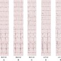
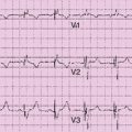
Electrocardiogram
Findings
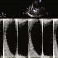
Echocardiogram
Cardiovascular Computed Tomographic Angiography
Findings
Coronary Venous Findings
Other Cardiovascular Findings
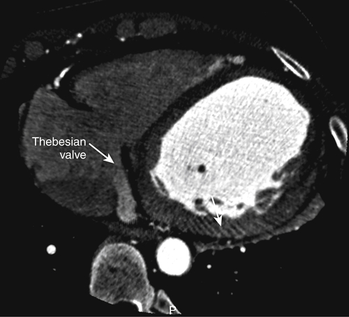
FIGURE 17-1 A two-dimensional oblique cardiac computed tomography angiography image demonstrates a prominent Thebesian valve (white arrows) covering the coronary sinus ostium.
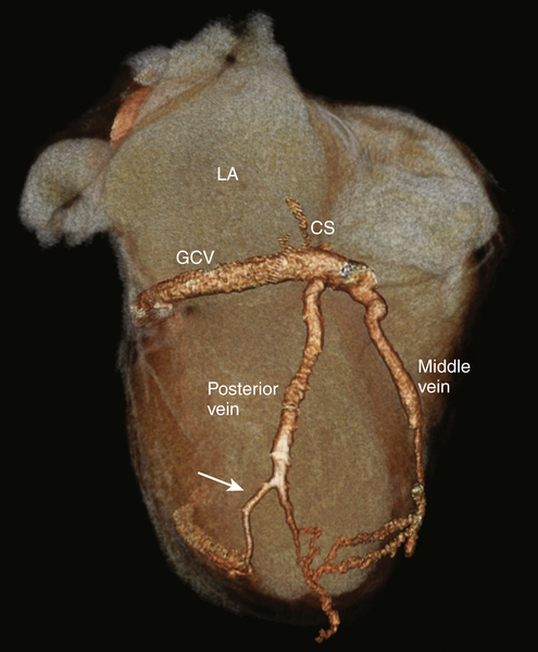
FIGURE 17-2 A three-dimensional cardiac computed tomography angiography reconstruction shows the coronary venous system. A posterior cardiac vein was present branching off 1.5 cm after the coronary sinus ostium coursing posterolaterally. At 6 cm distal to the takeoff of the posterior vein, the vein bifurcated, with one branch coursing posteriorly while the other branch coursed laterally. There was no evidence of a branch vein in the lateral territory of the left ventricle. The vein targeted for implant is shown (white arrow). CS, Coronary sinus; GCV, great cardiac vein; LA, left atrium.
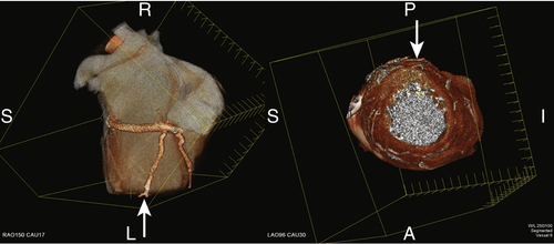
FIGURE 17-3 A three-dimensional cardiac computed tomography angiography reconstruction demonstrates localization of the myocardial segments associated with the posterior vein. The arrows demonstrate the myocardial location of the bifurcation of the vein at the mid to apical ventricular level.
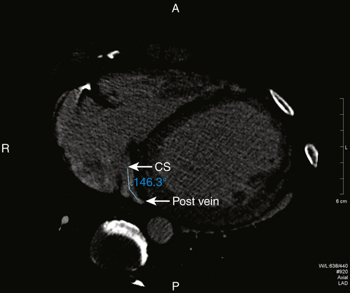
FIGURE 17-4 A two-dimensional oblique cardiac computed tomography angiography image shows the gentle angulation of 146 degrees of the posterior vein off of the coronary sinus. CS, Coronary sinus; Post vein, posterior vein.
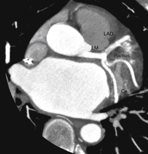
FIGURE 17-5 A two-dimensional oblique cardiac computed tomography angiography image showing the left coronary artery circulation without significant coronary artery disease. Cx, Circumflex coronary artery; LAD, left anterior descending coronary artery; LM, left main coronary artery; Ramus, ramus intermedius coronary artery.
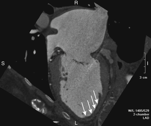
FIGURE 17-6 A two-dimensional chamber cardiac computed tomography angiography image demonstrates the left ventricle to be moderately dilated with thinning and aneurysmal dilatation of the apex. A thin layer of mural thrombus was seen in the region of the apical aneurysm (white arrows). The left atrium was severely enlarged.
Focused Clinical Questions and Discussion Points
Question
Discussion
Question
Discussion
Question
Discussion
Question
Discussion
Question
Discussion
Final Diagnosis
Plan of Action
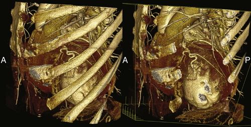
FIGURE 17-7 A three-dimensional cardiac computed tomography angiography reconstruction demonstrates the relationship of the left ventricle to the skeletal structures. These views could potentially be useful to planning an epicardial approach to left ventricular lead placement.
Intervention
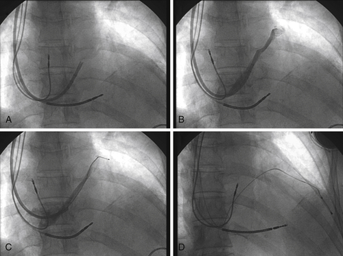
FIGURE 17-8 Fluoroscopy images show the multipurpose catheter that has been advanced beyond the Thebesian valve into the main body of the great cardiac vein, with subsequent deployment of the left ventricular endovascular lead.
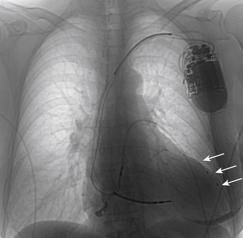
FIGURE 17-9 A chest radiograph demonstrates the final left ventricular lead position (white arrows).
Outcome
Selected References
1. Auricchio A., Sorgente A., Soubelet E. et al. Accuracy and usefulness of fusion imaging between three-dimensional coronary sinus and coronary veins computed tomographic images with projection images obtained using fluoroscopy. Europace. 2009;11:1483–1490.
2. Cao M., Chang P., Garon B. et al. Cardiac resynchronization therapy: double cannulation approach to coronary venous lead placement via a prominent Thebesian valve. pacing and clinical electrophysiology. Pacing Clin Electrophysiol. 2012 in press.
3. Girsky M.J., Shinbane J.S., Ahmadi N. et al. Prospective randomized trial of venous cardiac computed tomographic angiography for facilitation of cardiac resynchronization therapy. Pacing Clin Electrophysiol. 2010;33:1182–1187.
4. Jongbloed M.R., Lamb H.J., Bax J.J. et al. Noninvasive visualization of the cardiac venous system using multislice computed tomography. J Am Coll Cardiol. 2005;45:749–753.
5. Mao S., Shinbane J.S., Girsky M.J. et al. Coronary venous imaging with electron beam computed tomographic angiography: three-dimensional mapping and relationship with coronary arteries. Am Heart J. 2005;150:315–322.
6. Mark D.B., Berman D.S., Budoff M.J. et al. ACCF/ACR/AHA/NASCI/SAIP/SCAI/SCCT 2010 expert consensus document on coronary computed tomographic angiography: a report of the American College of Cardiology Foundation Task Force on Expert Consensus Documents. Circulation. 2010;121:2509–2543.
7. Mlynarski R., Mlynarska A., Sosnowski M. Anatomical variants of coronary venous system on cardiac computed tomography. Circulation. 2011;75:613–618.
8. Shinbane J.S., Girsky M.J., Mao S. et al. Thebesian valve imaging with electron beam CT angiography: implications for resynchronization therapy. Pacing Clin Electrophysiol. 2004;27:1331–1332.
9. Taylor A.J., Cerqueira M., Hodgson J.M. et al. ACCF/SCCT/ACR/AHA/ASE/ASNC/NASCI/SCAI/SCMR 2010 appropriate use criteria for cardiac computed tomography: a report of the American College of Cardiology Foundation Appropriate Use Criteria Task Force, the Society of Cardiovascular Computed Tomography, the American College of Radiology, the American Heart Association, the American Society of Echocardiography, the American Society of Nuclear Cardiology, the North American Society for Cardiovascular Imaging, the Society for Cardiovascular Angiography and Interventions, and the Society for Cardiovascular Magnetic Resonance. Circulation. 2010;122:e525–e555.
10. Van de Veire N.R., Marsan N.A., Schuijf J.D. et al. Noninvasive imaging of cardiac venous anatomy with 64-slice multi-slice computed tomography and noninvasive assessment of left ventricular dyssynchrony by 3-dimensional tissue synchronization imaging in patients with heart failure scheduled for cardiac resynchronization therapy. Am J Cardiol. 2008;101:1023–1029.