Procedure 17 Anterior Thoracolumbar Spinal Fusion via Open Approach for Idiopathic Scoliosis
Indications
 To halt progression of spinal curvature
 To restore spinal alignment and balance


 To allow for a thoracoscopic approach in selected cases
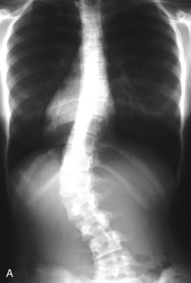
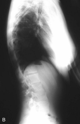
 Appropriate candidates typically include Lenke type 1 (single structural thoracic) and Lenke type 5 (single structural thoracolumbar/lumbar) curves (Figure 17-1, A and B).
Indications Pitfalls
• Anterior surgery tends to be “kyphogenic.” This may not be appropriate in curves with thoracic kyphosis greater than 40 degrees or in cases of thoracolumbar (“junctional”) kyphosis or lumbar hypolordosis.
• Patients weighing greater than 60 kg, with curves greater than 75 degrees, with or without hyperkyphosis, are not candidates for single-rod thoracic open or thoracoscopic fusion.
Examination/Imaging


Positioning
 The surgical approach is always from the convex side of the curvature in the lateral decubitus position.
Positioning Pearls
• Copious padding of all bony and soft tissue prominences, such as the axilla (“axillary roll”) and lateral knee, is required to prevent a compressive neuropathy or pressure necrosis of the upper or lower extremity or trunk.
• Electrophysiologic monitoring of the upper extremities will allow early detection of compressive neuropathies, prompting immediate repositioning and/or repadding of the upper extremity.
• A flat radiolucent table and beanbag positioner are utilized.
• When utilized, unobstructed fluoroscopic access is verified before preparation and draping.
• Neurophysiologic monitoring of spinal cord function, using both somatosensory evoked potential and transcranial motor evoked potential monitoring, is recommended to optimize patient safety.
Portals/Exposures


Thoracolumbar

Lumbar

Portals/Exposures Pearls
Procedure: Thoracolumbar Spine Fusion via an Open Approach Using Single-Rod Instrumentation
Step 1: Anterior Release and Diskectomy
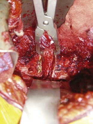
 Once adequate spinal exposure has been obtained, transection of the anterior longitudinal ligament and complete diskectomy is performed to, or including, the posterior longitudinal ligament.
Step 1 Pearls
• Release of the anterior longitudinal ligament and complete diskectomy allows for maximal curve flexibility and deformity correction.
• A malleable ribbon retractor placed around to the far side of the disk space affords protection to the vascular structures.
• For severe, rigid curvatures that have developed wedging of the vertebral bodies, vertebral osteotomy may be required to gain maximum correction.
Step 2: Placement of the Anterior Vertebral Body Screws
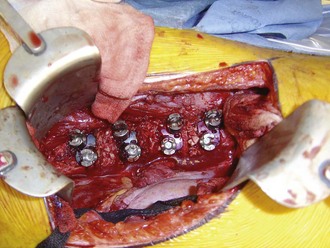
 The entry point of the vertebral body screw is preferentially the junction of the pedicular origin and the vertebral body, crossing the center of the vertebral body and directed perpendicularly across to the far side. At the cephalad and caudad end vertebrae a staple can be impacted to prevent pullout or plow-through of the screws. At intervening levels, a washer can be placed to help distribute load.

Step 3: End-Plate Ablation

Step 4: Placement of Anterior Interbody Structural Supports
 Anterior interbody structural supports are important for overall strength of the construct and for setting the desired lordosis in the lumbar spine. When using single-rod instrumentation, a structural support is placed at each level in the lumbar spine, starting from the apex and moving cephalad and caudad. The graft should be impacted toward the concave side and positioned to lie flush with the anterior aspect of the vertebral body when setting the lordosis. Upon placement of the structural grafts, the spinal curvature is usually fully corrected and the lumbar lordosis is “set” before rod placement.

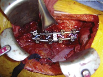
Step 5: Rod Placement


Procedure: Thoracolumbar Spine Fusion via an Open Approach Using Dual-Rod Instrumentation

Step 2: Placement of the Anterior Vertebral Body Screws
 With systems using a dual-rod construct, there is typically a two-holed tined vertebral staple that is implanted first, which then receives the vertebral body screws (Figure 17-4). When positioning these devices, care should be taken not to allow the anterior screw to be too close to the anterior aspect of the vertebral body, because vertebral body fracture can occur. The proper staple is selected by identifying the size that maximizes the coverage of the lateral aspect of the vertebral body without violating the adjacent disk space.


Step 5: Rod Placement


Postoperative Care and Expected Outcomes
 The patient is mobilized beginning on the day following surgery. If single-rod instrumentation is utilized, a spinal orthosis is fashioned and worn for 3 to 4 months postoperatively. If dual-rod instrumentation is utilized, no brace is employed.

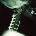
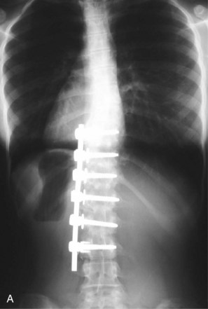
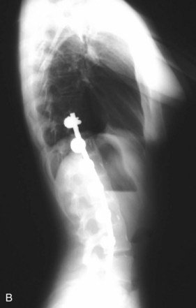
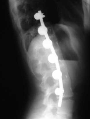
 Radiographs are taken to assess the implant stability, maintenance of correction and maturation of the fusion at 1, 3, 6, and 12 months postoperatively (Figures 17-6, A and B, and 17-7). Yearly radiographs are obtained thereafter until definitive fusion is seen.
Fricka KB, Mahar AT, Newton PO. Biomechanical analysis of anterior scoliosis instrumentation: differences between single and dual rod systems with and without structural interbody support. Spine. 2002;27:702-706.
Lowe TG, Alongi PR, Smith DA, et al. Anterior single-rod instrumentation for thoracolumbar adolescent idiopathic scoliosis with and without the use of structural interbody support. Spine. 2003;28:2221-2232.
Lowe TG, Enguidanos ST, Smith DA, et al. Single-rod versus dual-rod anterior instrumentation for idiopathic scoliosis: a biomechanical study. Spine. 2005;30:311-317.
Polly DWJr, Cunningham BW, Kuklo TR, et al. Anterior thoracic scoliosis constructs: effect of rod diameter and intervertebral cages on multi-segmental construct stability. Spine J. 2003;3:213-219.
Potter BK, Kuklo TR, Lenke LG. Radiographic outcomes of anterior spinal fusion versus posterior spinal fusion with thoracic pedicle screws for treatment of Lenke type I adolescent idiopathic scoliosis curves. Spine. 2005;30:1859-1866.
Rhee JM, Bridwell KH, Won DS, et al. Sagittal plane analysis of adolescent idiopathic scoliosis: the effect of anterior versus posterior instrumentation. Spine. 2002;27:2350-2356.
Smith JA, Deviren V, Berven S, Bradford DS. Does instrumented anterior scoliosis surgery lead to kyphosis, pseudarthrosis or inadequate correction in adults? Spine. 2002;27:529-534.