[level-membership-for-surgery-category]
Procedure 11 Posterior C1-C2 Fusion
Harms and Magerl Techniques
Technique A: Posterior C1-2 Polyaxial Screw and Rod Fixation (Harms Technique) (Harms and Melcher, 2001)
Indications


Indications Pearls
• Similar risk of vertebral artery injury compared to transarticular screws (Yoshida et al, 2006).
• Does not require the use of sublaminar wires, thus decreasing the risk of neural injury.
• Screws can assist in the C1-2 reduction.
• Integrity of the posterior arch of C1 is not required.
• Can be incorporated as part of fusions to the occiput and/or the subaxial spine.
Examination/Imaging
 Neurologic and musculoskeletal examination.
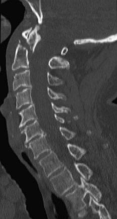
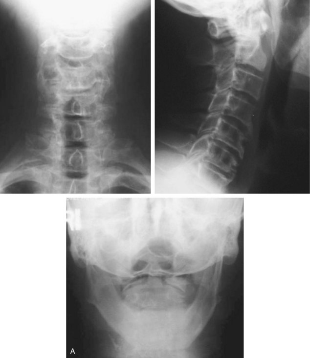
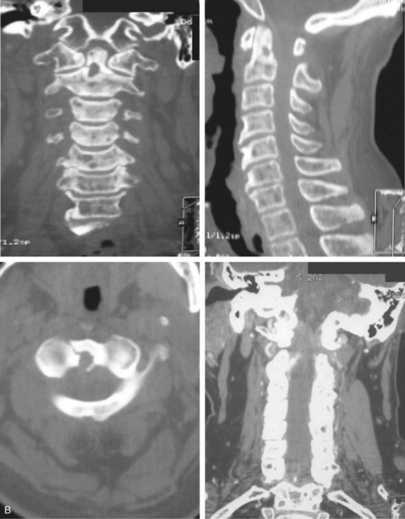
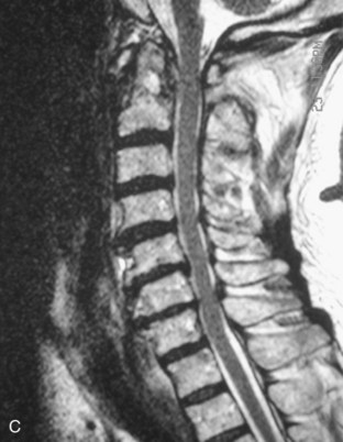
 Preoperative imaging should include plain radiographs (Figure 11-3, A), computed tomography (CT) (Figure 11-3, B), CT angiography, and magnetic resonance imaging (MRI) (Figure 11-3, C) of the cervical spine.

Surgical Anatomy
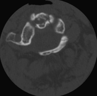
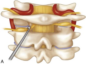
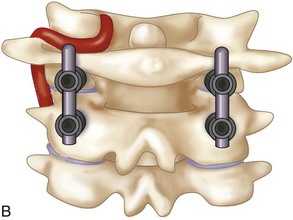
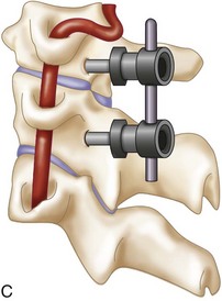
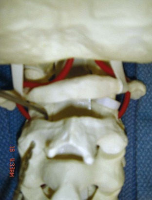
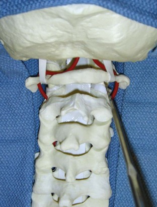
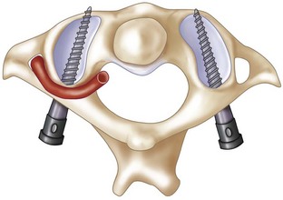
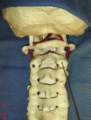
 The posterior arch of C1 and the C1-2 facet joint are key anatomic landmarks for the placement of C1 lateral mass screws. The dorsal root ganglion of C2 lies just posterior to the starting point of the C1 screw and must be gently retracted caudally for adequate exposure (Figure 11-4, A). The starting point for the C1 screw is at the midpoint of the inferior portion of the C1 lateral mass at its junction with the posterior arch. The more superior and medial trajectory of the screws, when compared with transarticular screws, decreases the risk of vertebral artery injury (Figure 11-4, B and C)
 The ponticulus posticus or congenital arcuate foramen is a common bony anomaly of the atlas (Young et al, 2005) (Figure 11-4, D). It is a bony arch on the cephalad aspect of the C1 lamina that contains the vertebral artery. If present, it can easily be confused with the lamina of C1 and must be identified during the posterior dissection and placement of C1 lateral mass screws to prevent vertebral artery injury.
Positioning
 After an awake fiberoptic nasotracheal intubation is performed, a nasogastric tube is inserted for intraoperative gastric drainage.
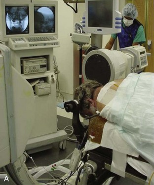
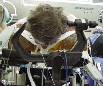
 If the patient is immobilized in a halo vest preoperatively, either the halo can be left in place and attached directly to the Mayfield headholder using an adapter or it can be removed. If the halo ring is removed, the patient is placed in Mayfield tongs and a hard cervical collar before being turned into the prone position. In coordination with anesthesia, the surgeon stands at the head of the hospital bed and stabilizes the patient’s neck. The patient is cautiously turned in the prone position on the operating table with the torso on bolsters or a four-poster frame. The Mayfield tongs or the halo ring is fixed to the operating table using a Mayfield headholder with the neck in a neutral position (Figure 11-5, A and B).

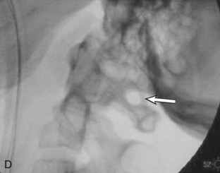
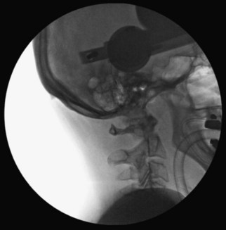
 Using fluoroscopic C-arm, proper alignment of the atlantoaxial bony structures is confirmed with the radiograph centered at C1-2. The lateral fluoroscopic image must not be oblique at C1-2; otherwise, malpositioning of the drill can result in erroneous screw placement (Figure 11-6).


Positioning Pearls
• An open-mouth view is obtained by placing an appropriate-size roll of sterile gauze in the patient’s mouth to facilitate a clear open-mouth view.
• In very osteopenic bone, inverse (negative) radiologic images can be utilized for better bony visualization.
• On the lateral C-arm image, the posterior occiput should be flexed off the posterior arch of C1 to facilitate screw placement at C1.
Portals/Exposures
 An electric razor is used to remove all hair from the patient’s occipital, suboccipital, and neck regions. If a definitive fusion is being performed, the posterior iliac crest is also shaved for bone graft harvesting.


 A 10-blade scalpel is used to sharply incise the skin in the midline from the occiput to C3-4.


 To decrease the risk of injuring the vertebral artery on the cephalic surface of the C1 lamina, identify the lamina and follow the caudal edge of the posterior arch during exposure of C1. If present, the ponticulus posticus or congenital arcuate foramen must be identified during the posterior dissection, because it can easily be confused with the lamina of C1 (Young et al, 2005).
 The dissection is complete with exposure of the suboccipital rim of the foramen magnum.
Portals/Exposures Pearls
• The C2 spinous process is an easily identifiable landmark. The C2 spinous process sits more posterior relative to the arch of C1 and can be used to orient your dissection.
• The cephalad orientation of the C2 pars necessitates exposure down to C3. This facilitates the placement of the C2 pars screw.
• The lateral dissection should not be carried past the lateral border of the C1-2 articulation to avoid iatrogenic injury of the vertebral artery.
Procedure
Step 1
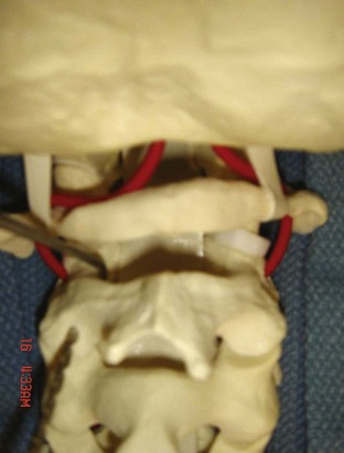
 The dorsal root ganglion of C2 must be carefully retracted caudally to expose the starting point for the C1 lateral mass screw. The starting point for the C1 screw is at the midpoint of the inferior portion of the C1 lateral mass at its junction with the posterior arch.
 C-arm imaging can be used to verify the midpoint and trajectory of the C1 lateral mass screw.

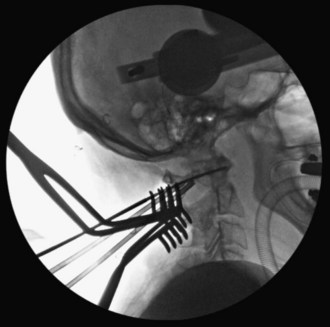
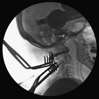
 With the tip of the drill pointing anterior through the lateral mass of C1, a 2-mm drill bit is used to drill a bicortical pilot hole in a straight to slightly convergent trajectory in the anteroposterior plane, and parallel to the posterior arch of C1 in the sagittal plane (Seal et al, 2009). Drill position is confirmed on AP and lateral C-arm fluoroscopic images (Figures 11-7 and 11-8).


Step 1 Pearls
• Critical landmarks for the accurate placement of C1 lateral mass screws
• The ponticulus posticus or congenital arcuate foramen can be confused with the C1 lamina and must be identified to prevent vertebral artery injury during the posterior dissection and placement of C1 lateral mass screws (Young et al, 2005).
• A superior and slightly medial trajectory (0 to 10 degrees) of the C1 lateral mass screw decreases the risk of vertebral artery injury (Figure 11-11).
Step 2
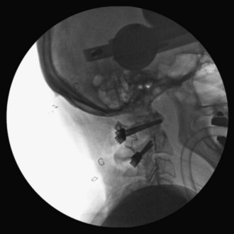
 At C2, a no. 4 Penfield is used to define the medial border of the C2 pars. The starting point for the C2 pars interarticularis screw is in the superior and medial quadrant of the C2 pars. The entry point for placement of the C2 pars screw is marked with the 2-mm high-speed burr (Figure 11-12).


 The drill hole is tapped, and the 3.5-mm polyaxial screw is placed into the C2 pars (Wait et al, 2009) (Figure 11-13).

Step 2 Pearls
• Intraoperative landmarks, the preoperative thin-cut (1-mm) axial CT scan, and lateral and open-mouth fluoroscopic imaging can all aid in the accurate placement of the C1 lateral mass and C2 pars interarticularis screws.
• Alternative procedures for patients with unilateral vertebral artery anomalies at C2
Step 3
 If reduction of C1 is necessary, the patient’s head can be repositioned before fixation of the rods to the screws. When performed, the reduction is visualized under fluoroscopy.
Step 3 Pearls
• C1-2 reduction can be accomplished by direct manipulation of the C1 and C2 screws. The authors’ recommendation is to obtain a reduction preoperatively, if possible while the patient is awake, to assess neurologic status. Alternatively, reduction can be performed after the patient is positioned prone on the operating table before preparation and draping.
Step 4
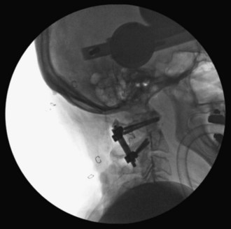
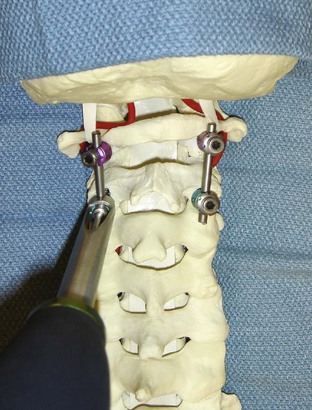
 The interconnecting rods are measured and secured with locking nuts (Figure 11-14).
 Distraction or compression of the construct can be accomplished at this time.
 The locking nuts are tightened with a torque wrench (Figure 11-15).
Step 4 Pearls
• With this technique, one can avoid damage to the C1-2 facet joints, and the rods and screws can be used as temporary fracture fixation without definitive fusion (i.e., type II and III odontoid fractures) (Harms and Melcher, 2001). Eventual removal of the hardware can allow the patient to regain atlantoaxial motion after fracture healing has occurred.
• The integrity of the posterior arch of C1 is not necessary for stable fixation.
• Patients with rheumatoid arthritis often have instability adjacent to the atlantoaxial region requiring a more extensive fusion. This technique can be incorporated as part of fusions to the occiput and/or the subaxial spine.
Step 5
 For definitive fusion, posterior iliac crest bone graft is harvested. The posterior superior iliac crest is palpated, and an 8-cm line centered over the crest is marked with a sterile marking pen. A 10-blade scalpel is used to incise the skin. Self-retaining retractors are inserted.


 Small gouges are used to harvest cancellous bone graft through the cortical window.
 The graft is placed in a sterile cup mixed with the patient’s blood and covered.

 The retractors are removed and the incision is closed in layers.
Step 6


Step 7
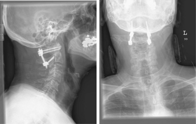
 Final AP and lateral cervical radiographs are obtained to assess placement of the hardware and alignment of the atlantoaxial region.
 The wound is closed securely in a layered fashion obliterating any dead space.
 A subfascial drain is placed if thought to be needed by the surgeon.

 A rigid cervical collar (i.e., Philadelphia or Miami J) is secured in place.
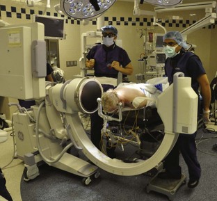
 The surgeon stands at the head of the operating table and is responsible for stabilizing the neck, when the patient is repositioned onto the hospital bed in the supine position. The patient is removed from the Mayfield headholder (Figure 11-16).
Postoperative Care and Expected Outcomes
 The patient should be taken to the recovery room or the surgical intensive care unit (SICU) for postoperative recovery.
 Supine and upright lateral cervical radiographs should be obtained in the cervical collar to assess stability on postoperative day 1. If atlantoaxial stability has been obtained, the patient can be mobilized (see Figure 11-16).

 A postoperative CT scan can be obtained if there is any question concerning screw placement.
 The patient can be discharged from the hospital when medically stable.
 Rigid cervical collar immobilization is used postoperatively.


Postoperative Pitfalls
• Screw malposition can result in
Technique B: C1-2 Transarticular Facet Screws (Magerl Technique)
Indications


Indications Pitfalls
• Potential vertebral artery injury
• Maximum biomechanical stability achieved when combined with posterior wiring for three-point fixation (Henriques et al, 2000)
Examination and Imaging
 Complete neurologic and musculoskeletal examination
 Preoperative imaging should include plain radiographs (see Figure 11-3, A), CT (see Figure 11-3, B), CT angiography, and MRI (see Figure 11-3, C) of the cervical spine.

Surgical Anatomy
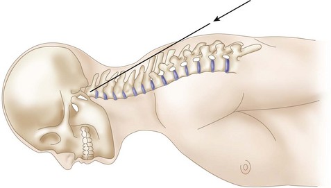
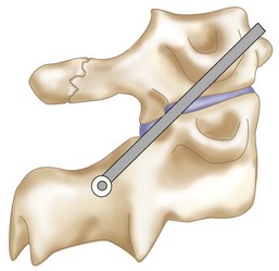
 The cephalad orientation of the C1-2 transarticular screw and the final position of the neck necessary for adequate atlantoaxial alignment may require percutaneous placement of the transarticular facet screws (Figure 11-17).
 The ponticulus posticus or congenital arcuate foramen is a common bony anomaly of the atlas (Young et al, 2005). It is a bony arch on the cephalad aspect of the C1 lamina that contains the vertebral artery. If present, it can easily be confused with the lamina of C1 and must be identified during the posterior dissection to prevent vertebral artery injury.
 The gray ramus communicans of the C2 nerve is a reliable landmark for locating the entry point for a screw on the C2 pars (Cavalcanti et al, 2010).
Positioning
 After an awake fiberoptic nasotracheal intubation is performed, a nasogastric tube is inserted for intraoperative gastric drainage.


Portals/Exposures
 An electric razor is used to remove all hair from the patient’s occipital, suboccipital, and neck regions. If transarticular screw fixation with bone graft and sublaminar wiring is being performed, the posterior iliac crest is also shaved for bone graft harvesting.
 The skin surfaces of the neck and posterior iliac crest are prepared and draped in sterile fashion.


 A 10-blade scalpel is used to sharply incise the skin in the midline from the occiput to C3-4.


 The dissection is complete with exposure of the suboccipital rim of the foramen magnum.
Portals/Exposures Pearls
• The C2 spinous process is an easily identifiable landmark. The C2 spinous process sits more posterior relative to the arch of C1 and can be used to orient your dissection.
• If present, the ponticulus posticus or congenital arcuate foramen can easily be confused with the lamina of C1. It must be identified during the posterior dissection to prevent vertebral artery injury.
• The lateral dissection should not be carried past the lateral border of the C1-2 articulation, to avoid iatrogenic injury of the vertebral artery.
Procedure
Step 1
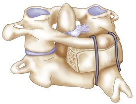
 If posterior bone graft and sublaminar wiring are going to be utilized with transarticular screw fixation, bone graft harvesting and passage of the C1 sublaminar wire should be completed before the insertion of the transarticular screws.


Step 1 Pearls
• Stabilization of the C1-2 segment with transarticular screws can make the passage of the sublaminar wire more difficult and dangerous. Therefore it is the authors’ preference to pass the sublaminar wire before screw fixation.
• The C1 sublaminar wire can aid in reduction of the atlantoaxial segment, thus facilitating placement of the transarticular screws.
Step 2
 To prepare for the passage of the sublaminar wire, the ligamentum flavum on the underlying surfaces of the posterior arches of C1 and C2 is elevated off the superior and inferior surfaces of the lamina using a microcurette.
 A Woodson dissector can be used to carefully free any adherent portions of dura.

Step 3
 A no. 4 Penfield elevator is used to define the medial border of the C2 pars. Care must be taken not to violate the dura with the Penfield. The Penfield can be used to protect the C2 nerve root and venous plexus with gentle rostral retraction. The removal of any ligamentum flavum adjacent to the C2 lamina will improve visualization of the C2 pars and atlantoaxial joint and help with orientation for transarticular screw placement.

Step 4


Step 5


Step 6


Step 7
 The K-wire drill guide is inserted into the soft tissue sheath. A 1.2-mm diameter K-wire is then inserted into the drill guide and secured to a reversible pneumatic drill.

 The starting point for screw entry is in the C2 fossa, 2 to 3 mm lateral to the junction of the lamina and lateral mass (Figures 11-18 and 11-19).


Step 7 Pearls
• To decrease the risk of vertebral artery injury, the K-wire must not be directed laterally, and must follow the medial wall of the C2 pars.
• Intraoperative bony landmarks, the preoperative thin-cut (1-mm) axial CT scan, and AP and lateral fluoroscopic imaging can all aid in the accurate placement of the K-wires and C1-2 transarticular screws (Weidner et al, 2000).
• Screw fixation with a cannulated 3.5-mm screw system is the authors’ preferred method for transarticular screw placement.
Step 8
 A cannulated drill bit is placed and drilled over the K-wire under C-arm fluoroscopy. Care must be taken as the drill is advanced over the K-wire. Because there is a risk of bending the tip of the K-wire as it crosses the C1-2 facet joint and penetrates the C1 cortical surface, impingement of the K-wire in the cannulated drill can occur. This can result in subsequent advancement of the K-wire into the posterior oropharyngeal fossa.

 The near cortex is tapped with a cannulated tap through the tissue sheath.
 A cannulated fully threaded 3.5-mm cortical screw of appropriate length (usually 40 to 45 mm) is inserted with a cannulated screwdriver over the K-wire under fluoroscopic visualization. The anterior cortex of the C1 lateral mass should be purchased with the screw. Unicortical screws may be considered to avoid neurovascular injury in cases with satisfactory bone quality (Cyr et al, 2008) (Figure 11-20).
 The K-wire is removed and screw placement can be confirmed with C-arm fluoroscopic imaging.
 Steps 5 to 7 are repeated for the contralateral C1-2 transarticular screw.
Step 9


Step 10


Step 11


Step 12


Step 13
 The wound is closed securely in a layered fashion, obliterating any dead space.

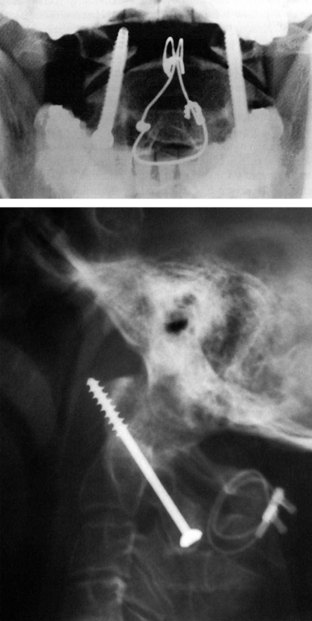
 Final AP and lateral cervical radiographs are obtained to assess placement of the hardware and alignment of the atlantoaxial region (Figure 11-23).
 A rigid cervical collar (i.e., Philadelphia or Miami-J) is secured in place.

Postoperative Care and Expected Outcomes
 The patient should be taken to the recovery room or the surgical intensive care unit (SICU) for postoperative recovery.


 A postoperative CT scan can be obtained if there is any question concerning screw placement.
 The patient can be discharged from the hospital when medically stable.
 Rigid cervical collar immobilization is used for approximately 8 to 12 weeks postoperatively.


 Fusion can be achieved in nearly 100% of cases, although 16.7% of patients may experience complications (Finn and Apfelbaum, 2010).
Postoperative Pitfalls
• Screw malposition can result in:
Cavalcanti D, Agrawal A, Garcia-Gonzalez U, et al. Anterolateral C1-C2 transarticular fixation for atlantoaxial arthrodesis: landmarks, working area, and angles of approach. Operative Neurosurg. 2010;67:38-42.
Currier B, Maus T, Eck J, et al. Relationship of the internal carotid artery to the anterior aspect of the C1 vertebra. Spine. 2008;33:635-639.
Cyr S, Currier B, Eck J, et al. Fixation strength of unicortical versus bicoritcal C1-C2 transarticular screws. Spine J. 2008;8:661-665.
Finn M, Apfelbaum R. Atlantoaxial transarticular screw fixation: update on techniques and outcomes in 269 patients. Neurosurgery. 2010;66A:184-192.
Harms J, Melcher R. Posterior C1-C2 fusion with polyaxial screw and rod fixation. Spine. 2001;26:2467-2471.
Henriques T, Cunningham B, Olerud C, et al. Biomechanical comparison of five different atlantoaxial posterior fixation techniques. Spine. 2000;25:2877-2883.
Jeanneret B, Magerl F. Primary posterior fusion C1/2 in odontoid fractures: indications, techniques, and results of transarticular screw fixation. J Spinal Disord. 1992;5:464-475.
Jun BY. Anatomic study for ideal and safe posterior C1-C2 transarticular screw fixation. Spine. 1998;23:1703-1707.
Madawi A, Solanki G, Casey AT, et al. Variation of the groove in the axis vertebra for the vertebral artery: implications for instrumentation. J Bone Joint Surg Br. 1997;79:820-823.
Magerl F, Seemann P-S. Stable posterior fusion of the atlas and axis by transarticular screw fixation. In: Kehr P, Weidner A, editors. Cervical Spine I. New York: Springer Wien; 1986:322-327.
Seal C, Zarro C, Gelb D, et al. C1 lateral mass anatomy: proper placement of lateral mass screws. J Spinal Disord Tech. 2009;22:516-523.
Tan M, Wang H, Wang Y, et al. Morphometric evaluation of screw fixation in atlas via posterior arch and lateral mass. Spine. 2003;28:888-895.
Wait S, Ponce F, Colle K, et al. Importance of the C1 anterior tubercle depth and lateral mass geometry when placing C1 lateral mass screws. Neurosurgery. 2009;65:952-957.
Weidner A, Wahler M, Chiu T, Ullrich C. Modification of C1-C2 transarticular screw fixation by image-guided surgery. Spine. 2000;25:2668-2674.
Yoshida M, Feo M, Fujibayashi S, Nakamura T. Comparison of the anatomical risk for vertebral artery injury associated with the C2-pars interarticularis screw and atlantoaxial transarticular screw. Spine. 2006;31:E513-E517.
Young JP, Young PH, Ackermann MJ, et al. The ponticulus posticus: implications for screw insertion into the first cervical lateral mass. J Bone Joint Surg Am. 2005;87:2495-2498.
[/level-membership-for-surgery-category][not-level-membership-for-surgery-category]
Procedure 11 Posterior C1-C2 Fusion
Harms and Magerl Techniques
Technique A: Posterior C1-2 Polyaxial Screw and Rod Fixation (Harms Technique) (Harms and Melcher, 2001)
Indications
Indications Pearls
• Similar risk of vertebral artery injury compared to transarticular screws (Yoshida et al, 2006).
• Does not require the use of sublaminar wires, thus decreasing the risk of neural injury.
• Screws can assist in the C1-2 reduction.
• Integrity of the posterior arch of C1 is not required.
• Can be incorporated as part of fusions to the occiput and/or the subaxial spine.
Examination/Imaging
Neurologic and musculoskeletal examination.
Preoperative imaging should include plain radiographs (Figure 11-3, A), computed tomography (CT) (Figure 11-3, B), CT angiography, and magnetic resonance imaging (MRI) (Figure 11-3, C) of the cervical spine.
Surgical Anatomy
The posterior arch of C1 and the C1-2 facet joint are key anatomic landmarks for the placement of C1 lateral mass screws. The dorsal root ganglion of C2 lies just posterior to the starting point of the C1 screw and must be gently retracted caudally for adequate exposure (Figure 11-4, A). The starting point for the C1 screw is at the midpoint of the inferior portion of the C1 lateral mass at its junction with the posterior arch. The more superior and medial trajectory of the screws, when compared with transarticular screws, decreases the risk of vertebral artery injury (Figure 11-4, B and C)
The ponticulus posticus or congenital arcuate foramen is a common bony anomaly of the atlas (Young et al, 2005) (Figure 11-4, D). It is a bony arch on the cephalad aspect of the C1 lamina that contains the vertebral artery. If present, it can easily be confused with the lamina of C1 and must be identified during the posterior dissection and placement of C1 lateral mass screws to prevent vertebral artery injury.
Positioning
After an awake fiberoptic nasotracheal intubation is performed, a nasogastric tube is inserted for intraoperative gastric drainage.
If the patient is immobilized in a halo vest preoperatively, either the halo can be left in place and attached directly to the Mayfield headholder using an adapter or it can be removed. If the halo ring is removed, the patient is placed in Mayfield tongs and a hard cervical collar before being turned into the prone position. In coordination with anesthesia, the surgeon stands at the head of the hospital bed and stabilizes the patient’s neck. The patient is cautiously turned in the prone position on the operating table with the torso on bolsters or a four-poster frame. The Mayfield tongs or the halo ring is fixed to the operating table using a Mayfield headholder with the neck in a neutral position (Figure 11-5, A and B).
Using fluoroscopic C-arm, proper alignment of the atlantoaxial bony structures is confirmed with the radiograph centered at C1-2. The lateral fluoroscopic image must not be oblique at C1-2; otherwise, malpositioning of the drill can result in erroneous screw placement (Figure 11-6).
Positioning Pearls
• An open-mouth view is obtained by placing an appropriate-size roll of sterile gauze in the patient’s mouth to facilitate a clear open-mouth view.
• In very osteopenic bone, inverse (negative) radiologic images can be utilized for better bony visualization.
• On the lateral C-arm image, the posterior occiput should be flexed off the posterior arch of C1 to facilitate screw placement at C1.
Portals/Exposures
An electric razor is used to remove all hair from the patient’s occipital, suboccipital, and neck regions. If a definitive fusion is being performed, the posterior iliac crest is also shaved for bone graft harvesting.
A 10-blade scalpel is used to sharply incise the skin in the midline from the occiput to C3-4.
To decrease the risk of injuring the vertebral artery on the cephalic surface of the C1 lamina, identify the lamina and follow the caudal edge of the posterior arch during exposure of C1. If present, the ponticulus posticus or congenital arcuate foramen must be identified during the posterior dissection, because it can easily be confused with the lamina of C1 (Young et al, 2005).
The dissection is complete with exposure of the suboccipital rim of the foramen magnum.
Portals/Exposures Pearls
• The C2 spinous process is an easily identifiable landmark. The C2 spinous process sits more posterior relative to the arch of C1 and can be used to orient your dissection.
• The cephalad orientation of the C2 pars necessitates exposure down to C3. This facilitates the placement of the C2 pars screw.
• The lateral dissection should not be carried past the lateral border of the C1-2 articulation to avoid iatrogenic injury of the vertebral artery.
Procedure
Step 1
The dorsal root ganglion of C2 must be carefully retracted caudally to expose the starting point for the C1 lateral mass screw. The starting point for the C1 screw is at the midpoint of the inferior portion of the C1 lateral mass at its junction with the posterior arch.
C-arm imaging can be used to verify the midpoint and trajectory of the C1 lateral mass screw.
With the tip of the drill pointing anterior through the lateral mass of C1, a 2-mm drill bit is used to drill a bicortical pilot hole in a straight to slightly convergent trajectory in the anteroposterior plane, and parallel to the posterior arch of C1 in the sagittal plane (Seal et al, 2009). Drill position is confirmed on AP and lateral C-arm fluoroscopic images (Figures 11-7 and 11-8).
Step 1 Pearls
• Critical landmarks for the accurate placement of C1 lateral mass screws
• The ponticulus posticus or congenital arcuate foramen can be confused with the C1 lamina and must be identified to prevent vertebral artery injury during the posterior dissection and placement of C1 lateral mass screws (Young et al, 2005).
• A superior and slightly medial trajectory (0 to 10 degrees) of the C1 lateral mass screw decreases the risk of vertebral artery injury (Figure 11-11).
Step 2
At C2, a no. 4 Penfield is used to define the medial border of the C2 pars. The starting point for the C2 pars interarticularis screw is in the superior and medial quadrant of the C2 pars. The entry point for placement of the C2 pars screw is marked with the 2-mm high-speed burr (Figure 11-12).
The drill hole is tapped, and the 3.5-mm polyaxial screw is placed into the C2 pars (Wait et al, 2009) (Figure 11-13).
Step 2 Pearls
• Intraoperative landmarks, the preoperative thin-cut (1-mm) axial CT scan, and lateral and open-mouth fluoroscopic imaging can all aid in the accurate placement of the C1 lateral mass and C2 pars interarticularis screws.
• Alternative procedures for patients with unilateral vertebral artery anomalies at C2
Step 3
If reduction of C1 is necessary, the patient’s head can be repositioned before fixation of the rods to the screws. When performed, the reduction is visualized under fluoroscopy.
Step 3 Pearls
• C1-2 reduction can be accomplished by direct manipulation of the C1 and C2 screws. The authors’ recommendation is to obtain a reduction preoperatively, if possible while the patient is awake, to assess neurologic status. Alternatively, reduction can be performed after the patient is positioned prone on the operating table before preparation and draping.
Step 4
The interconnecting rods are measured and secured with locking nuts (Figure 11-14).
Distraction or compression of the construct can be accomplished at this time.
The locking nuts are tightened with a torque wrench (Figure 11-15).
Step 4 Pearls
• With this technique, one can avoid damage to the C1-2 facet joints, and the rods and screws can be used as temporary fracture fixation without definitive fusion (i.e., type II and III odontoid fractures) (Harms and Melcher, 2001). Eventual removal of the hardware can allow the patient to regain atlantoaxial motion after fracture healing has occurred.
• The integrity of the posterior arch of C1 is not necessary for stable fixation.
• Patients with rheumatoid arthritis often have instability adjacent to the atlantoaxial region requiring a more extensive fusion. This technique can be incorporated as part of fusions to the occiput and/or the subaxial spine.
Step 5
For definitive fusion, posterior iliac crest bone graft is harvested. The posterior superior iliac crest is palpated, and an 8-cm line centered over the crest is marked with a sterile marking pen. A 10-blade scalpel is used to incise the skin. Self-retaining retractors are inserted.
[/not-level-membership-for-surgery-category]
