Procedure 10 C2 Translaminar Screw Fixation
Figures 10-4 through 10-7 and 10-9 through 10-12 redrawn with permission from Leonard JR, Wright NM. Pediatric atlantoaxial fixation with bilateral, crossing C-2 translaminar screws. Technical note. J Neurosurg 2006;104:59-63.
Indications


Examination/Imaging
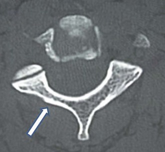
 CT imaging is critically important to determine the suitability of the C2 laminae to accept a 3.5-mm diameter screw. In this image the right laminae (arrow) is too narrow to safely place a laminar screw (Figure 10-1).
Treatment Options
• C1-C2 transarticular screw fixation: Magerl technique (if vertebral artery anatomy favorable)
• C1 lateral mass to C2 pedicle screw fixation: Harms technique (if vertebral artery anatomy favorable)
• Posterior C1-2 wiring techniques
Surgical Anatomy
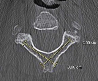
 Intact posterior elements of C2 are crucial to the placement of translaminar screws. The spinous process of C2 is typically bifid. The laminae thickness needs to be evaluated preoperatively by computed tomography (CT), and the screw length should be measured. Screw length is determined from the axial CT slice that shows the thickest portion of the laminae of C2 (Figure 10-2).
Positioning
 Similar to positioning for C1 lateral mass screws and other fixation techniques for C2, the patient is prone in a Mayfield headholder. The neck is placed in a neutral position.
 Hair is shaved as needed to expose the inion rostrally down to the midcervical spine.
Positioning Pearls
• Although it is tempting to place the neck in a flexed position to facilitate surgical exposure, this should be avoided.
• It is important to place the neck in an anatomically neutral position.
• Gently taping the shoulders can facilitate radiographic visualization of the C1-2 complex.
• Gently taping the upper back can reduce redundant neck folds in the more obese patient, facilitating skin opening and closure.
Positioning Pitfalls
• Placing the patient in a flexed position, while facilitating exposure, will result in stabilizing the atlantoaxial complex in a flexed position, resulting in permanent difficulty with swallowing and high patient dissatisfaction.
• Placing the patient in an overly extended position will make surgical exposure more difficult.
Portals/Exposures
 A skin incision is made from the inion down to approximately the C3 level.
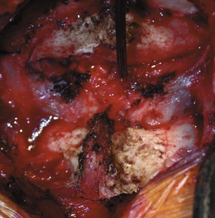
 After dividing the dorsal fascia in the midline, the paraspinal muscles are reflected from the suboccipital skull, the dorsal arch of C1, and the spinous process and laminae of C2 (Figure 10-3).

Portals/Exposures Pearls
• The electrocautery can be safely used to reflect the paraspinal muscles off of the spinous process and laminae of C2, but this should not be used to expose the lateral aspects of the dorsal C1 laminae to avoid possible vertebral artery injury.
• Frequent repositioning of the retractors to tension the paraspinal muscles facilitates exposure.
Procedure
Step 1: Making the Entry Hole for the First Translaminar Screw
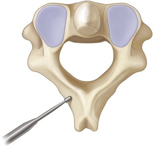
 The high-speed drill is used to make a small cortical entry at the junction of the spinous process and lamina on one side (Figure 10-4). The trajectory of the first screw must take into account the planned trajectory of the subsequent second translaminar screw (Figure 10-5). The author favors placing the more rostral screw first.
Step 2: Drilling the Contralateral Lamina
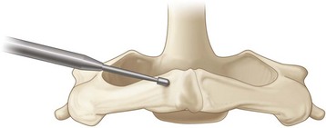
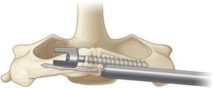
 The hand drill is used to drill the contralateral lamina to the depth determined by preoperative imaging (Figure 10-6).
 After placing the drill guide at the drilled entry point, the drill is angled to match the down slope of the contralateral lamina (Figure 10-7).

Step 2 Pearls
• Drilling with the hand drill allows tactile feedback to alert the surgeon if the ventral lamina has been penetrated.
• It is important to measure the length of the lamina first and to set the drill guide accordingly.
• For grossly unstable injuries, gentle countertraction against the opposite side of the spinous process with a periosteal elevator will prevent rotation of C2 during drilling.
Step 3: Verification of Safe Preparation of the Lamina
 Intraoperative or postoperative radiographs are of limited value in determining accurate intralaminar screw placement.
 The integrity of the drilled path must be verified before screw placement.
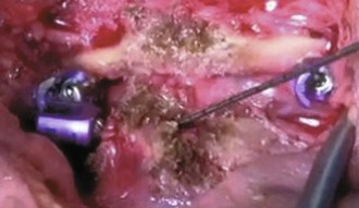
 A ball-tip probe is used to palpate the tract, paying special attention to the ventral aspect of the tract (Figure 10-8).
Step 3 Pearls
• Gently bending the tip of the ball-tip probe at the distal end helps provide directional palpation.
• If the ball-probe identifies a ventral breakout, the length of the viable tract before the breakout can be determined by placing a straight clamp or mosquito clamp on the ball-tip probe at the entry point and measuring the distance to the tip of the ball-tip probe once removed. A shorter screw can be placed to purchase the spinous process rather than the lamina.
Step 4: Placement of the First Screw
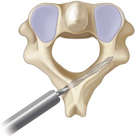
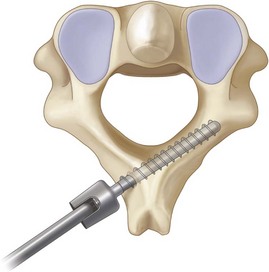
 The appropriate-length screw (as determined by preoperative CT and intraoperative verification of the drill tract) is placed (Figure 10-9).
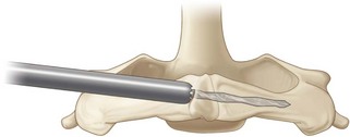
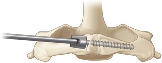
 Similar to step 2, the screw tip is placed into the entry hole, and then the screwdriver is angled to match the down slope of the contralateral lamina (Figure 10-10).
Step 5: Placement of the Second Screw
 Steps 1 to 4 are repeated for the contralateral lamina.
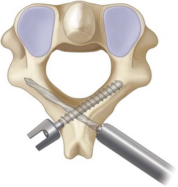
 For initial preparation of the entry point, a more caudal location is chosen to allow passage of the drill and screw past the first screw (Figures 10-11 and 10-12).

 It remains critically important to verify the integrity of the drill tract with the ball-tip probe.
Step 6: Connection of the C2 Laminar Screws to C1 Lateral Mass Screws
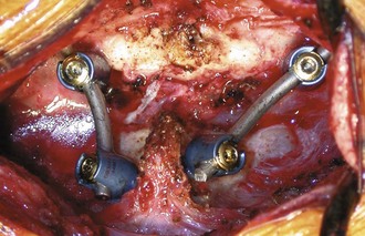
 For atlantoaxial constructs, the C1 lateral mass screws need to be connected to the C2 laminar screws.
 The right C1 lateral mass screw will be connected to the right-projecting head of the left laminar screw, and vice-versa (Figure 10-13).


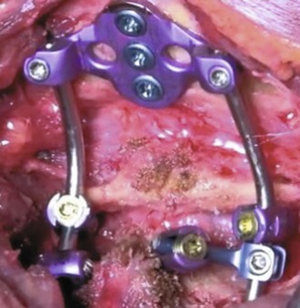
 Alternatively, angled offset connectors can be used to incorporate the dorsal C2 screw heads into longer constructs, shown here in an occipital–C1-2 construct (Figure 10-14).


Postoperative Care and Expected Outcomes


Cassinelli EH, Lee M, Skalak A, Ahn NU, Wright NM. Anatomic considerations for the placement of C2 laminar screws. Spine. 2006;31:2767-2771.
Dorward I, Wright NM. Seven years experience with C2 translaminar screw fixation–clinical experience and review of the literature. Neurosurgery. 2011;68(6):1490-1499.
Gorek J, Acaroglu E, Berven S, Yousef A, Puttlitz CM. Constructs incorporating intralaminar C2 screws provide rigid stability for atlantoaxial fixation. Spine. 2005;30:1513-1518.
Jea A, Sheth RN, Vanni S, Green BA, Levi AD. Modification of Wright’s technique for placement of bilateral crossing C2 translaminar screws: technical note. Spine J. 2008;8:656-660.
Lehman RA, Sasso RC, Helgeson MD, et al. Accuracy of intraoperative plain radiographs to detect violations of intralaminar screws placed into the C2 vertebrae—a reliability study. Spine. 2007;32:3036-3040.
Leonard JR, Wright NM. Pediatric atlantoaxial fixation with bilateral, crossing C-2 translaminar screws. Technical note. J Neurosurg. 2006;104:59-63.
Menendez JA, Wright NM. Techniques of posterior C1-C2 stabilization. Neurosurgery. 2007;60:103-111.
Parker SL, McGirt MJ, Garces-Ambrossi GL, et al. Translaminar versus pedicle screw fixation of C2: comparison of surgical morbidity and accuracy of 313 consecutive screws. Neurosurgery. 2009;64:343-348. discussion 348-9
Reddy C, Ingalhalikar AV, Channon S, et al. In vitro biomechanical comparison of transpedicular versus translaminar C-2 screw fixation in C2-3 instrumentation. J Neurosurg Spine. 2007;7:414-418.
Wang MY. C2 crossing laminar screws: cadaveric morphometric analysis. Neurosurgery. 2006;59:84-87.
Wang MY. Cervical crossing laminar screws: early clinical results and complications. Neurosurgery. 2007;61:311-315.
Wright NM. Posterior C2 fixation using bilateral, crossing C2 laminar screws: case series and technical note. J Spinal Disord Tech. 2004;17:158-162.
Wright NM. Translaminar rigid screw fixation of the axis. J Neurosurg Spine. 2005;3:409-414.