Getting Started
WHAT IS KINESIOLOGY?
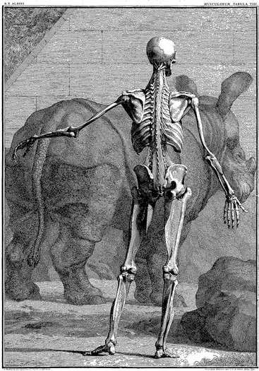
The origins of the word kinesiology are from the Greek kinesis, to move, and logy, to study. Kinesiology of the Musculoskeletal System: Foundations for Rehabilitation serves as a guide to kinesiology by focusing on the anatomic and biomechanical interactions within the musculoskeletal system. The beauty and complexity of these interactions have been captured by many great artists, such as Michelangelo Buonarroti (1475-1564) and Leonardo da Vinci (1452-1519). Their work likely inspired the creation of the classic text Tabulae Sceleti et Musculorum Corporis Humani, published in 1747 by the anatomist Bernhard Siegfried Albinus (1697-1770). A sample of this work is presented in Figure 1-1.
OVERALL PLAN OF THIS TEXTBOOK
This text is divided into four sections. Section I: Essential Topics of Kinesiology includes Chapters 1 to 4. To get the reader started, Chapter 1 provides many of the fundamental concepts and terminology related to kinesiology. A glossary is provided at the end of Chapter 1 with definitions of these fundamental concepts and terms. Chapters 2 to 4 describe the necessary background regarding the mechanics of joints, physiology of muscle, and review of applied biomechanics.
The material presented in Section I sets forth the kinesiologic foundation for the more anatomic- and regional-based chapters included in Sections II to IV. Section II (Chapters 5 to 8) describes the kinesiology related to the upper extremity; Section III (Chapters 9 to 11) covers the kinesiology involving primarily the axial skeleton and trunk; finally, Section IV (Chapters 12 to 15) presents the kinesiology of the lower extremity, including a closing chapter that focuses on walking.
KINEMATICS
Translation Compared with Rotation
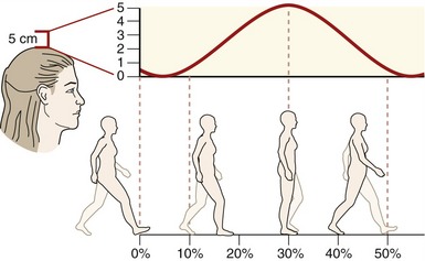
Translation describes a linear motion in which all parts of a rigid body move parallel to and in the same direction as every other part of the body. Translation can occur in either a straight line (rectilinear) or a curved line (curvilinear). During walking, for example, a point on the head moves in a general curvilinear manner (Figure 1-2).
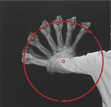
Movement of the human body as a whole is often described as a translation of the body’s center of mass, located generally just anterior to the sacrum. Although a person’s center of mass translates through space, it is powered by muscles that rotate the limbs. The fact that limbs rotate can be appreciated by watching the path created by a fist while the elbow is flexing (Figure 1-3). (It is customary in kinesiology to use the phrases “rotation of a joint” and “rotation of a bone” interchangeably.)
The primary variables related to kinematics are position, velocity, and acceleration. Specific units of measurement are needed to indicate the quantity of these variables. Units of meters or feet are used for translation, and degrees or radians are used for rotation. In most situations, Kinesiology of the Musculoskeletal System uses the International System of Units, adopted in 1960. This system is abbreviated SI, for Système International d’Unités, the French name. This system of units is widely accepted in many journals related to kinesiology and rehabilitation. The kinematic conversions between the more common SI units and other measurement units are listed in Table 1-1. Additional units of measurements are described in Chapter 4.
TABLE 1-1.
Common Conversions between Units of Kinematic Measurements
| SI Units | English Units |
| 1 meter (m) = 3.28 feet (ft) | 1 ft = 0.305 m |
| 1 m = 39.37 inches (in) | 1 in = 0.0254 m |
| 1 centimeter (cm) = 0.39 in | 1 in = 2.54 cm |
| 1 m = 1.09 yards (yd) | 1 yd = 0.91 m |
| 1 kilometer (km) = 0.62 miles (mi) | 1 mi = 1.61 km |
| 1 degree = 0.0174 radians (rad) | 1 rad = 57.3 degrees |
Osteokinematics
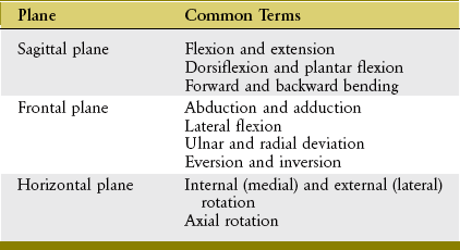
Osteokinematics describes the motion of bones relative to the three cardinal (principal) planes of the body: sagittal, frontal, and horizontal. These planes of motion are depicted in the context of a person standing in the anatomic position as in Figure 1-4. The sagittal plane runs parallel to the sagittal suture of the skull, dividing the body into right and left sections; the frontal plane runs parallel to the coronal suture of the skull, dividing the body into front and back sections. The horizontal (or transverse) plane courses parallel to the horizon and divides the body into upper and lower sections. A sample of the terms used to describe the different osteokinematics is shown in Table 1-2. More specific terms are defined in the chapters that describe the various regions of the body.
AXIS OF ROTATION
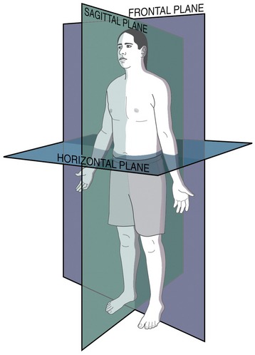
Bones rotate around a joint in a plane that is perpendicular to an axis of rotation. The axis is typically located through the convex member of the joint. The shoulder, for example, allows movement in all three planes and therefore has three axes of rotation (Figure 1-5). Although the three orthogonal axes are depicted as stationary, in reality, as in all joints, each axis shifts slightly throughout the range of motion. The axis of rotation would remain stationary only if the convex member of a joint were a perfect sphere, articulating with a perfectly reciprocally shaped concave member. The convex members of most joints, like the humeral head at the shoulder, are imperfect spheres with changing surface curvatures. The issue of a migrating axis of rotation is discussed further in Chapter 2.
DEGREES OF FREEDOM
Degrees of freedom are the number of independent directions of movements allowed at a joint. A joint can have up to three degrees of angular freedom, corresponding to the three cardinal planes. As depicted in Figure 1-5, for example, the shoulder has three degrees of angular freedom, one for each plane. The wrist allows only two degrees of freedom (rotation within sagittal and frontal planes), and the elbow allows just one (within the sagittal plane).
Unless specified differently throughout this text, the term degrees of freedom indicates the number of permitted planes of angular motion at a joint. From a strict engineering perspective, however, degrees of freedom apply to translational (linear) as well as angular movements. All synovial joints in the body possess at least some translation, driven actively by muscle or passively because of the natural laxity within the structure of the joint. The slight passive translations that occur in most joints are referred to as accessory movements (or joint “play”) and are commonly defined in three linear directions. From the anatomic position, the spatial orientation and direction of accessory movements can be described relative to the three axes of rotation. In the relaxed glenohumeral joint, for example, the humerus can be passively translated slightly: anterior-posteriorly, medial-laterally, and superior-inferiorly (see short, straight arrows near proximal humerus in Figure 1-5). At many joints, the amount of translation is used clinically to test the health of the joint. Excessive translation of a bone relative to the joint may indicate ligamentous injury or abnormal laxity. In contrast, a significant reduction in translation (accessory movements) may indicate pathologic stiffness within the surrounding periarticular connective tissues. Abnormal translation within a joint typically affects the quality of the active movements, potentially causing increased intra-articular stress and microtrauma.
OSTEOKINEMATICS: A MATTER OF PERSPECTIVE
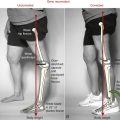
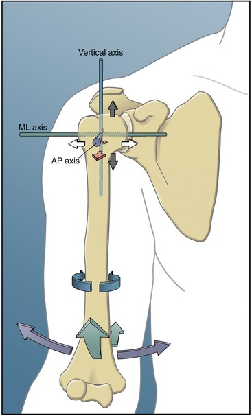
In general, the articulation of two or more bony or limb segments constitutes a joint. Movement at a joint can therefore be considered from two perspectives: (1) the proximal segment can rotate against the relatively fixed distal segment, and (2) the distal segment can rotate against the relatively fixed proximal segment. These two perspectives are shown for knee flexion in Figure 1-6. A term such as knee flexion, for example, describes only the relative motion between the thigh and leg. It does not describe which of the two segments is actually rotating. Often, to be clear, it is necessary to state the bone that is considered the primary rotating segment. As in Figure 1-6, for example, the terms tibial-on-femoral movement and femoral-on-tibial movement adequately describe the osteokinematics.
The lower extremities routinely perform both proximal-on-distal and distal-on-proximal segment kinematics. These kinematics reflect, in part, the two primary phases of walking: the stance phase, when the limb is planted on the ground under the load of body weight, and the swing phase, when the limb is advancing forward. Many other activities, in addition to walking, use both kinematic strategies. Flexing the knee in preparation to kick a ball, for example, is a type of distal-on-proximal segment kinematics (see Figure 1-6, A). Descending into a squat position, in contrast, is an example of proximal-on-distal segment kinematics (see Figure 1-6, B). In the latter example, a relatively large demand is placed on the quadriceps muscle of the knee to control the gradual descent of the body.
The terms open and closed kinematic chains are frequently used in the physical rehabilitation literature and clinics to describe the concept of relative segment kinematics.9,20,25 A kinematic chain refers to a series of articulated segmented links, such as the connected pelvis, thigh, leg, and foot of the lower extremity. The terms “open” and “closed” are typically used to indicate whether the distal end of an extremity is fixed to the earth or some other immovable object. An open kinematic chain describes a situation in which the distal segment of a kinematic chain, such as the foot in the lower limb, is not fixed to the earth or other immovable object. The distal segment therefore is free to move (see Figure 1-6, A). A closed kinematic chain describes a situation in which the distal segment of the kinematic chain is fixed to the earth or another immovable object. In this case the proximal segment is free to move (see Figure 1-6, B). These terms are employed extensively to describe methods of applying resistive exercise to muscles, especially to the joints of the lower limb.
Arthrokinematics
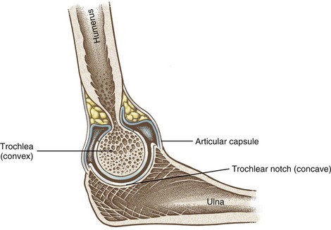
Arthrokinematics describes the motion that occurs between the articular surfaces of joints. As described further in Chapter 2, the shapes of the articular surfaces of joints range from flat to curved. Most joint surfaces, however, are at least slightly curved, with one surface being relatively convex and one relatively concave (Figure 1-7). The convex-concave relationship of most articulations improves their congruency (fit), increases the surface area for dissipating contact forces, and helps guide the motion between the bones.
FUNDAMENTAL MOVEMENTS BETWEEN JOINT SURFACES
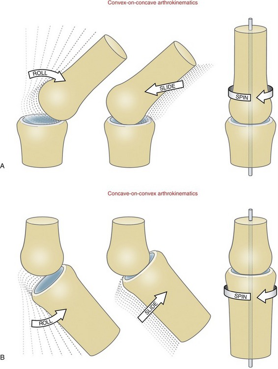
Three fundamental movements exist between curved joint surfaces: roll, slide, and, spin.27 These movements occur as a convex surface moves on a concave surface, and vice versa (Figure 1-8). Although other terms are used, these are useful for visualizing the relative movements that occur within a joint. The terms are formally defined in Table 1-3.
TABLE 1-3.
Three Fundamental Arthrokinematics: Roll, Slide, and Spin
| Movement | Definition | Analogy |
| Roll* | Multiple points along one rotating articular surface contact multiple points on another articular surface. | A tire rotating across a stretch of pavement |
| Slide† | A single point on one articular surface contacts multiple points on another articular surface. | A non-rotating tire skidding across a stretch of icy pavement |
| Spin | A single point on one articular surface rotates on a single point on another articular surface. | A toy top rotating on one spot on the floor |
Roll-and-Slide Movements: One primary way that a bone rotates through space is by a rolling of its articular surface against another bone’s articular surface. The motion is shown for a convex-on-concave surface movement at the glenohumeral joint in Figure 1-9, A. The contracting supraspinatus muscle rolls the convex humeral head against the slight concavity of the glenoid fossa. In essence, the roll directs the osteokinematic path of the abducting shaft of the humerus.22
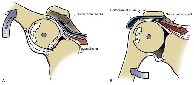
A rolling convex surface typically involves a concurrent, oppositely directed slide. As shown in Figure 1-9, A, the inferior-directed slide of the humeral head offsets most of the potential superior migration of the rolling humeral head. The offsetting roll-and-slide kinematics are analogous to a tire on a car that is spinning on a sheet of ice. The potential for the tire to rotate forward on the icy pavement is offset by a continuous sliding of the tire in the opposite direction to the intended rotation. A classic pathologic example of a convex surface rolling without an offsetting slide is shown in Figure 1-9, B. The humeral head translates upward and impinges on the delicate tissues in the subacromial space. The migration alters the relative location of the axis of rotation, which may alter the effectiveness of the muscles that cross the glenohumeral joint. As shown in Figure 1-9, A, the concurrent roll-and-slide motion maximizes the angular displacement of the abducting humerus and minimizes the net translation between joint surfaces. This mechanism is particularly important in joints in which the articular surface area of the convex member exceeds that of the concave member.
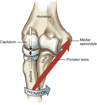
Spin: Another primary way that a bone rotates is by a spinning of its articular surface against the articular surface of another bone. This occurs as the radius of the forearm spins against the capitulum of the humerus during pronation of the forearm (Figure 1-10). Other examples include internal and external rotation of the 90-degree abducted glenohumeral joint, and flexion and extension of the hip. Spinning is the primary mechanism for joint rotation when the longitudinal axis of the long bone intersects the surface of its articular mate at right angles.
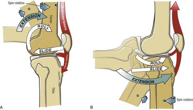
Motions That Combine Roll-and-Slide and Spin Arthrokinematics: Several joints throughout the body combine roll-and-slide with spin arthrokinematics. A classic example of this combination occurs during flexion and extension of the knee. As shown during femoral-on-tibial knee extension (Figure 1-11, A), the femur spins internally slightly as the femoral condyle rolls and slides relative to the fixed (stationary) tibia. These arthrokinematics are also shown as the tibia extends relative to the fixed femur in Figure 1-11, B. In the knee the spinning motion that occurs with flexion and extension occurs automatically and is mechanically linked to the primary motion of extension. As described in Chapter 13, the obligatory spinning rotation is based on the shape of the articular surfaces at the knee. The conjunct rotation helps to securely lock the knee joint when fully extended.
PREDICTING AN ARTHROKINEMATIC PATTERN BASED ON JOINT MORPHOLOGY
As previously stated, most articular surfaces of bones are either convex or concave. Depending on which bone is moving, a convex surface may rotate on a concave surface or vice versa (compare Figure 1-11, A with Figure 1-11, B). Each scenario presents a different roll-and-slide arthrokinematic pattern. As depicted in Figures 1-11, A and 1-9, A for the shoulder, during a convex-on-concave movement, the convex surface rolls and slides in opposite directions. As previously described, the contradirectional slide offsets much of the translation tendency inherent to the rolling convex surface. During a concave-on-convex movement, as depicted in Figure 1-11, B, the concave surface rolls and slides in similar directions. These two principles are very useful for visualizing the arthrokinematics during a movement. In addition, the principles serve as a basis for some manual therapy techniques. External forces may be applied by the clinician that assist or guide the natural arthrokinematics at the joint. For example, in certain circumstances, glenohumeral abduction can be facilitated by applying an inferior-directed force at the proximal humerus, simultaneously with an active-abduction effort. The arthrokinematic principles are based on the knowledge of the joint surface morphology.
CLOSE-PACKED AND LOOSE-PACKED POSITIONS AT A JOINT
The pair of articular surfaces within most joints “fits” best in only one position, usually in or near the very end range of a motion. This position of maximal congruency is referred to as the joint’s close-packed position.27 In this position, most ligaments and parts of the capsule are pulled taut, providing an element of natural stability to the joint. Accessory movements are typically minimal in a joint’s close-packed position.
KINETICS
Kinetics is a branch of the study of mechanics that describes the effect of forces on the body. The topic of kinetics is introduced here as it applies to the musculoskeletal system. A more detailed and mathematic approach to this subject matter is provided in Chapter 4.
 Body Weight Compared with Body Mass
Musculoskeletal Forces
IMPACT OF FORCES ON THE MUSCULOSKELETAL SYSTEM: INTRODUCTORY CONCEPTS AND TERMINOLOGY
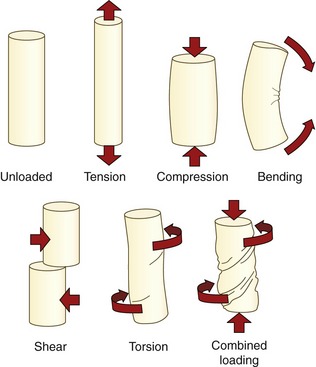
A force that acts on the body is often referred to generically as a load.23 Forces or loads that move, fixate, or otherwise stabilize the body also have the potential to deform and injure the body.23,24 The loads most frequently applied to the musculoskeletal system are illustrated in Figure 1-12. (See the glossary at the end of this chapter for formal definitions.) Healthy tissues are typically able to partially resist changes in their structure and shape. The force that stretches a healthy ligament, for example, is met by an intrinsic tension generated within the elongated (stretched) tissue. Any tissue weakened by disease, trauma, or prolonged disuse may not be able to adequately resist the application of the loads depicted in Figure 1-12. The proximal femur weakened by osteoporosis, for example, may fracture from the impact of a fall secondary to compression or torsion (twisting), shearing, or bending of the neck of the femur. Fracture may also occur in a severely osteoporotic hip after a very strong muscle contraction.
The ability of periarticular connective tissues to accept and disperse loads is an important topic of research within physical rehabilitation, manual therapy, and orthopedic medicine.14,18 Clinicians are very interested in how variables such as aging, trauma, altered activity or weight-bearing levels, or prolonged immobilization affect the load-accepting functions of periarticular connective tissues. One method of measuring the ability of a connective tissue to tolerate a load is to plot the force required to deform an excised tissue.8,22 This type of experiment is typically performed using animal or human cadaver specimens. Figure 1-13 shows a hypothetic graph of the tension generated by a generic ligament (or tendon) that has been stretched to a point of mechanical failure. The vertical (Y) axis of the graph is labeled stress, a term that denotes the internal resistance generated as the ligament resists deformation, divided by its cross-sectional area. (The units of stress are similar to pressure: N/mm2). The horizontal (X) axis is labeled strain, which in this case is the percent increase in a tissue’s stretched length relative to its original, preexperimental length.24 (A similar procedure may be performed by compressing rather than stretching an excised slice of cartilage or bone, for example, and then plotting the amount of stress produced within the tissue.29) Note in Figure 1-13 that under a relatively slight strain (stretch), the ligament produces only a small amount of stress (tension). This nonlinear or “toe” region of the graph reflects the fact that the collagen fibers within the tissue are initially wavy or crimped and must be drawn taut before significant tension is measured.18 Further elongation, however, shows a linear relationship between stress and strain. The ratio of the stress (Y) caused by an applied strain (X) in the ligament is a measure of its stiffness (often referred to as Young’s modulus). All normal connective tissues within the musculoskeletal system exhibit some degree of stiffness. The clinical term “tightness” usually implies a pathologic condition of abnormally high stiffness.
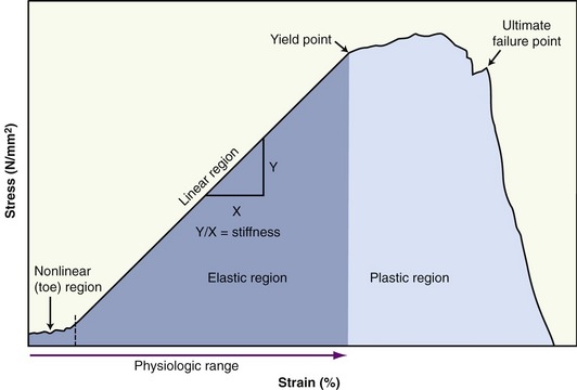
The initial nonlinear and subsequent linear regions of the curve shown in Figure 1-13 are often referred to as the elastic region. Ligaments, for example, are routinely strained within the lower limits of their elastic region. The anterior cruciate ligament, for example, is strained about 4% during an isometric contraction of the quadriceps with the knee flexed to 15 degrees.3,4 It is important to note that a healthy and relatively young ligament that is strained within the elastic zone returns to its original length (or shape) once the deforming force is removed. The area under the curve (in darker blue) represents elastic deformation energy. Most of the energy used to deform the tissue is released when the force is removed. Even in a static sense, elastic energy can do useful work at the joints. When stretched even a moderate amount into the elastic zone, ligaments and other connective tissues perform important joint stabilization functions.
A tissue that is elongated beyond its physiologic range eventually reaches its yield point. At this point, increased strain results in only marginal increased stress (tension). This physical behavior of an overstretched (or overcompressed) tissue is known as plasticity. The overstrained tissue has experienced plastic deformation. At this point microscopic failure has occurred and the tissue remains permanently deformed. The area under this region of the curve (in lighter blue) represents plastic deformation energy. Unlike elastic deformation energy, plastic energy is not recoverable in its entirety even when the deforming force is removed. As elongation continues, the ligament eventually reaches its ultimate failure point, the point when the tissue partially or completely separates and loses its ability to hold any level of tension. Most healthy tendons fail at about 8% to 13% beyond their prestretched length.31
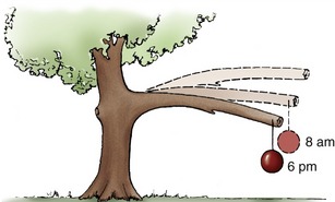
The graph in Figure 1-13 does not indicate the variable of time of load application. Tissues in which the physical properties associated with the stress-strain curve change as a function of time are considered viscoelastic. Most tissues within the musculoskeletal system demonstrate at least some degree of viscoelasticity. One phenomenon of a viscoelastic material is creep. As demonstrated by the tree branch in Figure 1-14, creep describes a progressive strain of a material when exposed to a constant load over time. Unlike plastic deformation, creep is reversible. The phenomenon of creep helps to explain why a person is taller in the morning than at night. The constant compression caused by body weight on the spine throughout the day literally squeezes a small amount of fluid out of the intervertebral discs. The fluid is reabsorbed at night while the sleeping person is in a non–weight-bearing position.
The stress-strain curve of a viscoelastic material is also sensitive to the rate of loading of the tissue. In general, the slope of a stress-strain relationship when placed under tension or compression increases throughout its elastic range as the rate of the loading increases.24 The rate-sensitivity nature of viscoelastic connective tissues may protect surrounding structures within the musculoskeletal system. Articular cartilage in the knee, for example, becomes stiffer as the rate of compression increases,23 such as during running. The increased stiffness affords greater protection to the underlying bone at a time when forces acting on the joint are greatest.
In summary, similar to building materials such as steel, concrete, and fiberglass, the periarticular connective tissues within the human body possess unique physical properties when loaded or strained. In engineering terms, these physical properties are formally referred to as material properties. The topic of material properties of periarticular connective tissues (such as stress, strain, stiffness, plastic deformation, ultimate failure load, and creep) has a well-established literature base.* Although much of the data on this topic are from animal or cadaver research, they do provide insight into many aspects of patient care, including understanding mechanisms of injury, improving the design of orthopedic surgery, and judging the potential effectiveness of certain forms of physical therapy, such as prolonged stretching or application of heat to induce greater tissue extensibility.†
INTERNAL AND EXTERNAL FORCES
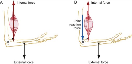
External forces are produced by forces acting from outside the body. These forces usually originate from either gravity pulling on the mass of a body segment or an external load, such as that of luggage or “free” weights, or physical contact, such as that applied by a therapist against the limb of a patient. Figure 1-15, A shows an opposing pair of internal and external forces: an internal force (muscle) pulling the forearm, and an external (gravitational) force pulling on the center of mass of the forearm. Each force is depicted by an arrow that represents a vector. By definition, a vector is a quantity that is completely specified by its magnitude and its direction. (Quantities such as mass and speed are scalars, not vectors. A scalar is a quantity that is completely specified by its magnitude and has no direction.)
SPECIAL FOCUS 1-2  Productive Antagonism: the Body’s Ability to Convert Passive Tension into Useful Work
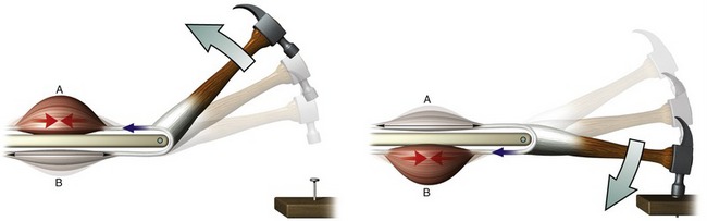
A stretched or elongated tissue within the body generally produces tension (i.e., a resistance force that opposes the stretch). In pathologic cases this tension may be abnormally large, thereby interfering with functional mobility. This textbook presents several examples, however, illustrating how relatively low levels of tension produced by stretched connective tissues (including muscle) perform useful functions. This phenomenon is called productive antagonism and is demonstrated for a pair of muscles in the simplified model in Figure 1-16. As shown by the figure on the left, part of the energy produced by active contraction of muscle A is transferred and stored as elastic energy in the stretched connective tissues within muscle B. The elastic energy is released as muscle B actively contracts to drive the nail into the board (right illustration). Part of the contractile energy produced by muscle B is used to stretch muscle A, and the cycle is repeated.
In order to completely describe a vector in a biomechanical analysis, its magnitude, spatial orientation, direction, and point of application must be known. The forces depicted in Figure 1-15 indicate these four factors.
1. The magnitude of the force vectors is indicated by the length of the shaft of the arrow.
2. The spatial orientation of the force vectors is indicated by the position of the shaft of the arrows. Both forces are oriented vertically, often referred to as the Y axis (further described in Chapter 4). The orientation of a force can also be described by the angle formed between the shaft of the arrow and a reference coordinate system.
3. The direction of the force vectors is indicated by the arrowhead. In the example depicted in Figure 1-15, A, the internal force acts upward, typically described in a positive Y sense; the external force acts downward in a negative Y sense. Throughout this text, the direction and spatial orientation of a muscle force and gravity are referred to as their line of force and line of gravity, respectively.
4. The point of application of the vectors is where the base of the vector arrow contacts the part of the body. The point of application of the muscle force is where the muscle inserts into the bone. The angle-of-insertion describes the angle formed between a tendon of a muscle and the long axis of the bone into which it inserts. In Figure 1-15, A, the angle-of-insertion is 90 degrees. The angle-of-insertion changes as the elbow rotates into flexion or extension. The point of application of the external force depends on whether the force is the result of gravity or the result of a resistance applied by physical contact. Gravity acts on the center of mass of the body segment (see Figure 1-15, A, dot at the forearm). The point of application of a resistance generated from physical contact can occur anywhere on the body.
As a push or a pull, all forces acting on the body cause a potential translation of the segment. The direction of the translation depends on the net effect of all the applied forces. In Figure 1-15, A, because the muscle force is three times greater than the weight of the forearm, the net effect of both forces would accelerate the forearm vertically upward. In reality, however, the forearm is typically prevented from accelerating upward by a joint reaction force produced between the surfaces of the joint. As depicted in Figure 1-15, B, the distal end of the humerus is pushing down with a reaction force (shown in blue) against the proximal end of the forearm. The magnitude of the joint reaction force is equal to the difference between the muscle force and external force. As a result, the sum of all vertical forces acting on the forearm is balanced, and net acceleration of the forearm in the vertical direction is zero. The system is therefore in static linear equilibrium.
Musculoskeletal Torques
Forces exerted on the body can have two outcomes. First, as depicted in Figure 1-15, A, forces can potentially translate a body segment. Second, the forces, if applied at some distance perpendicular to the axis of rotation, can also produce a potential rotation of the joint. The perpendicular distance between the axis of rotation of the joint and the force is called a moment arm. The product of a force and its moment arm produces a torque or a moment. A torque can be considered as a rotatory equivalent to a force. A force acting without a moment arm can push and pull an object generally in a linear fashion, whereas a torque rotates an object around an axis of rotation. This distinction is a fundamental concept in the study of kinesiology.
A torque is described as occurring around a joint in a plane perpendicular to a given axis of rotation. Figure 1-17 shows the torques produced within the sagittal plane by the internal and external forces introduced in Figure 1-15. The internal torque is defined as the product of the internal force (muscle) and the internal moment arm. The internal moment arm (see D in Figure 1-17) is the perpendicular distance between the axis of rotation and the internal force. As depicted in Figure 1-17, the internal torque has the potential to rotate the forearm around the elbow joint in a counterclockwise, or flexion, direction. (Other conventions for describing rotation direction are explored in Chapter 4.)
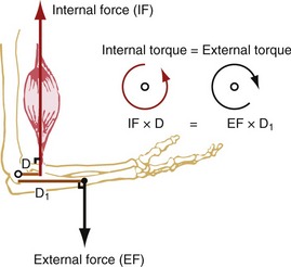
The external torque is defined as the product of the external force (such as gravity) and the external moment arm. The external moment arm (see D1 in Figure 1-17) is the perpendicular distance between the axis of rotation and the external force. The external torque has the potential to rotate the forearm around the elbow joint in a clockwise, or extension, direction. Because the magnitude of the opposing internal and external torques is assumed to be equal in Figure 1-17, no rotation occurs around the joint. This condition is referred to as static rotary equilibrium.
Torques are involved in most therapeutic situations with patients, especially when physical exercise or strength assessment is involved. A person’s “strength” is the product of their muscles’ force and, equally important, the internal moment arm: the perpendicular distance between the muscle’s line of force and the axis of rotation. Leverage describes the relative moment arm length possessed by a particular force. As explained further in Chapter 4, the length of a muscle’s moment arm, and hence leverage, changes constantly throughout a range of motion. This partially explains why a person is naturally stronger in certain parts of a joint’s range of motion.
Clinicians frequently apply manual resistance against their patients as a means to assess, facilitate, and challenge a particular muscle activity.12 The force applied against a patient’s extremity is usually perceived as an external torque by the patient’s musculoskeletal system. A clinician can challenge a particular muscle group by applying an external torque by way of a small manual force exerted a great distance from the joint, or a large manual force exerted close to the joint. Because torque is the product of a resistance force and its moment arm, either means can produce the same external torque against the patient. Modifying the force and external moment arm variables allows different strategies to be employed based on the strength and skill of the clinician.
SPECIAL FOCUS 1-3  Muscle-Produced Torques across a Joint: an Essential Concept in Kinesiology
How muscles produce torques across joints is one of the most important (and often difficult) concepts to understand in kinesiology. An understanding of this concept can be helped by considering a simple analogy between a muscle’s potential to produce a torque (i.e., rotation) and the action of a force attempting to swing open a door. The essential mechanics in both scenarios are surprisingly similar. This analogy is described with the assistance of Figure 1-18, A and B.
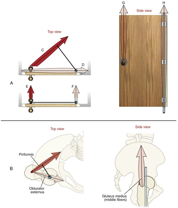
Figure 1-18, A shows top and side views of a door mounted on a vertical hinge (depicted in blue). Horizontally applied forces (C to F) represent different attempts at manually pulling open the door. Although all forces are assumed equal, only forces C and E (applied at the doorknob) are actually capable of rotating the door. This holds true because only these forces meet the basic requirements of producing a torque: (1) each force is applied in a plane perpendicular to the given axis of rotation (hinge in this case), and (2) each force is associated with a moment arm distance (dark black line originating at the hinge). In this example the torque is the product of the pulling force times its moment arm. Force E will produce a greater torque than force C because it has the longer moment arm (or greater leverage). Nevertheless, forces C and E both satisfy the requirement to produce a torque in the horizontal plane.
Forces G and H shown at the right in Figure 1-18, A also cannot rotate the door. Any force that runs parallel with an axis of rotation cannot produce an associated torque. A torque can be generated only by a force that is applied perpendicularly to a given axis of rotation. Forces G and H therefore possess no ability to produce a torque in the horizontal plane.
To complete this analogy, Figure 1-18, B shows two views of the hip joint along with three selected muscles. In this example the muscles are depicted as producing forces in attempt to rotate the femur within the horizontal plane. (The muscle forces in these illustrations are analogous to the manually applied forces applied to the door.) The axis of rotation at the hip, like the hinge on the door, is in a vertical direction (shown in blue). As will be explained, even though all the muscles are assumed to produce an identical force, only one is capable of actually rotating the femur (i.e., producing a torque).
The force vectors illustrated on the left side of Figure 1-18, B represent the lines of force of two predominately horizontally aligned muscles at the hip (the piriformis and obturator externus). The piriformis is capable of producing an external rotation torque within the horizontal plane for the same reasons given for the analogous force C applied to the door (Figure 1-18, A). Both forces are applied in a plane perpendicular to the axis of rotation, and each possesses an associated moment arm distance (depicted as the dark line). In sharp contrast, however, the obturator externus muscle cannot produce a torque in the horizontal plane. This muscle force (as with the analogous force D acting on the door) passes directly through the vertical axis of rotation. Although the muscle force will compress the joint surfaces, it will not rotate the joint, at least not in the horizontal plane. As will be described in Chapter 12, which studies the hip, changing the rotational position of the joint often creates a moment arm distance for a muscle. In this case the obturator externus may generate external rotation torque at the hip, although small.
The final component of this analogy is illustrated on the right of Figure 1-18, B. The middle fibers of the gluteus medius are shown attempting to rotate the femur in the horizontal plane around a vertical axis of rotation (depicted as a blue pin). Because the muscle force acts essentially parallel with the vertical axis of rotation (like forces G and H acting on the door), it is incapable of generating a torque in the horizontal plane. This same muscle, however, is very capable of generating torque in other planes, especially the frontal.
Muscle and Joint Interaction
TYPES OF MUSCLE ACTIVATION
A muscle is considered activated when it is stimulated by the nervous system. Once activated, a healthy muscle produces a force in one of three ways: isometric, concentric, and eccentric. The physiology of the three types of muscle activation is described in greater detail in Chapter 3 and briefly summarized subsequently.
Isometric activation occurs when a muscle is producing a pulling force while maintaining a constant length. This type of activation is apparent by the origin of the word isometric (from the Greek isos, equal, and metron, measure or length). During an isometric activation, the internal torque produced within a given plane at a joint is equal to the external torque; hence, there is no muscle shortening or rotation at the joint (Figure 1-19, A).
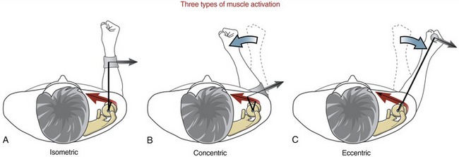
Concentric activation occurs as a muscle produces a pulling force as it contracts (shortens) (see Figure 1-19, B). Literally, concentric means “coming to the center.” During a concentric activation, the internal torque at the joint exceeds the opposing external torque. This is evident as the contracting muscle creates a rotation of the joint in the direction of the pull of the activated muscle.
Eccentric activation, in contrast, occurs as a muscle produces a pulling force as it is being elongated by another more dominant force. The word eccentric literally means “away from the center.” During an eccentric activation, the external torque around the joint exceeds the internal torque. In this case the joint rotates in the direction dictated by the relatively larger external torque, such as that produced by the hand-held external force in Figure 1-19, C. Many common activities employ eccentric activations of muscle. Slowly lowering a cup of water to a table, for example, is caused by the pull of gravity on the forearm and water. The activated biceps slowly elongates in order to control the descent. The triceps muscle, although considered as an elbow “extensor,” is most likely inactive during this particular process.
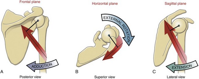
MUSCLE ACTION AT A JOINT
The first step in the analysis is to determine the planes of rotary motion (degrees of freedom) allowed at the joint. In this case the glenohumeral joint allows rotation in all three planes (see Figure 1-5). Before further analysis is made, it is theoretically possible, therefore, that any muscle crossing the shoulder can express an action in up to three planes. Figure 1-20, A shows the potential for the posterior deltoid to rotate the humerus in the frontal plane. The axis of rotation passes in an anterior-posterior direction through the humeral head. In the anatomic position, the line of force of the posterior deltoid passes inferior to the axis of rotation. By assuming that the scapula is stable, a contracting posterior deltoid would rotate the humerus toward adduction, with strength equal to the product of the muscle force multiplied by its internal moment arm (shown as the dark line from the axis). This same logic is next applied to determine the muscle’s action in the horizontal and sagittal planes. As depicted in Figure 1-20, B and C, it is apparent that the muscle is also an external (lateral) rotator and an extensor of the glenohumeral joint. As will be described throughout this text, it is common for a muscle that crosses a joint with at least two degrees of freedom to express multiple actions. A particular action may not be possible, however, if the muscle either lacks a moment arm or does not produce a force in the associated plane. Determining the potential action (or actions) of a muscle is a central theme in the study of kinesiology.
The logic just presented can be used to determine the action of any muscle in the body, at any joint. If available, an articulated skeleton model and a piece of string that mimics the line of force of a muscle are helpful in applying this logic. This exercise is particularly helpful when analyzing a muscle whose action switches depending on the position of the joint. One such muscle is the posterior deltoid. From the anatomic position the posterior deltoid is an adductor of the glenohumeral joint (previously depicted in Figure 1-20, A). If the arm is lifted (abducted) well overhead, however, the line of force of the muscle shifts just to the superior side of the axis of rotation. As a consequence the posterior deltoid actively abducts the shoulder. The example shows how one muscle can have opposite actions, depending on the position of the joint at the time of muscle activation. It is important, therefore, to establish a reference position for the joint when analyzing the actions of a muscle. One common reference position is the anatomic position (see Figure 1-4). Unless otherwise specified, the actions of muscles described throughout Sections II to IV in this text are based on the assumption that the joint is in the anatomic position.
Terminology Related to the Actions of Muscles: The following terms are often used when the actions of muscles are described:
• The agonist is the muscle or muscle group that is most directly related to the initiation and execution of a particular movement. For example, the tibialis anterior is the agonist for the motion of dorsiflexion of the ankle.
• The antagonist is the muscle or muscle group that is considered to have the opposite action of a particular agonist. For example, the gastrocnemius and soleus muscles are considered the antagonists to the tibialis anterior.
• Muscles are considered synergists when they cooperate during the execution of a particular movement. Actually, most meaningful movements of the body involve multiple muscles acting as synergists. Consider, for example, the flexor carpi ulnaris and flexor carpi radialis muscles during flexion of the wrist. The muscles act synergistically because they cooperate to flex the wrist. Each muscle, however, must neutralize the other’s tendency to move the wrist in a side-to-side (radial and ulnar deviation) fashion. Paralysis of one of the muscles significantly affects the overall action of the other.
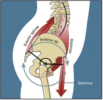
Another example of muscle synergy is described as a muscular force-couple. A muscular force-couple is formed when two or more muscles simultaneously produce forces in different linear directions, although the resulting torques act in the same rotary direction. A familiar analogy of a force-couple occurs between the two hands while turning a steering wheel of a car. Rotating the steering wheel to the right, for example, occurs by the action of the right hand pulling down and the left hand pulling up on the wheel. Although the hands are producing forces in different linear directions, they cause a torque on the steering wheel in the same rotary direction. The hip flexor and low back extensor muscles, for example, form a force-couple to rotate the pelvis in the sagittal plane around the hip joints (Figure 1-21).
Musculoskeletal Levers
Within the body, internal and external forces produce torques through a system of bony levers. Generically speaking, a lever is a simple machine consisting of a rigid rod suspended across a pivot point. The seesaw is a classic example of a first-class lever (Figure 1-22). One function of a lever is to convert a linear force into a rotary torque. As shown in the seesaw in Figure 1-22, a 672-N (about 150-lb) man sitting 0.91 m (about 3 ft) from the pivot point produces a torque that balances a boy weighing half his weight who is sitting twice the distance from the pivot point. In Figure 1-22, the opposing torques are equal (BWm × D = BWb × D1): the lever system therefore is balanced and in equilibrium. As indicated, the boy has the greatest leverage (D1 > D). An important underlying concept of the lever is that with unequal moment arm lengths, the opposing torques can balance each other only if the opposing forces (or body weights in the preceding figure) are of different magnitudes.
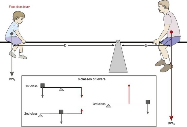
Levers are classified as either first, second, or third class (see inset in Figure 1-22).
First-Class Lever: As depicted in Figure 1-22, the first-class lever has its axis of rotation positioned between the opposing forces. An example of a first-class lever in the human body is the head-and-neck extensor muscles that control the posture of the head in the sagittal plane (Figure 1-23, A). As in the seesaw example, the head is held in equilibrium when the product of the muscle force (MF) multiplied by the internal moment arm (IMA) equals the product of head weight (HW) multiplied by its external moment arm (EMA). In first-class levers, the internal and external forces typically act in similar linear directions, although they produce torques in opposing rotary directions.
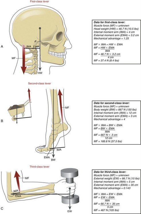
Second-Class Lever: A second-class lever always has two features. First, its axis of rotation is located at one end of a bone. Second, the muscle, or internal force, possesses greater leverage than the external force. Second-class levers are very rare in the musculoskeletal system. The classic example is the calf muscles producing the torque needed to stand on tiptoes (see Figure 1-23, B). The axis of rotation for this action is assumed to act through the metatarsophalangeal joints. Based on this assumption, the internal moment arm used by the calf muscles greatly exceeds the external moment arm used by body weight.
Third-Class Lever: As in the second-class lever, the third-class lever has its axis of rotation located at one end of a bone. The elbow flexor muscles use a third-class lever to produce the flexion torque required to support a weight in the hand (see Figure 1-23, C). Unlike with the second-class lever, the external weight supported by a third-class lever always has greater leverage than the muscle force. The third-class lever is the most common lever used by the musculoskeletal system.
MECHANICAL ADVANTAGE
The mechanical advantage (MA) of a musculoskeletal lever can be defined as the ratio of the internal moment arm to the external moment arm. Depending on the location of the axis of rotation, the first-class lever can have an MA equal to, less than, or greater than one. Second-class levers always have an MA greater than one. As depicted in the boxes associated with Figure 1-23, A and B, lever systems with an MA greater than one are able to balance the torque equilibrium equation by an internal (muscle) force that is less than the external force. Third-class levers always have an MA less than one. As depicted in Figure 1-23, C, in order to balance the torque equilibrium equation, the muscle must produce a force much greater than the opposing external force.
The majority of muscles throughout the musculoskeletal system function with an MA of much less than one. Consider, for example, the biceps at the elbow, the quadriceps at the knee, and the supraspinatus and deltoid at the shoulder.10,26 Each of these muscles attaches to bone relatively close to the joint’s axis of rotation. The external forces that oppose the action of the muscles typically exert their influence considerably distal to the joint, such as at the hand or the foot. Consider the force demands placed on the supraspinatus and deltoid muscles to maintain the shoulder abducted to 90 degrees while an external weight of 35.6 N (8 lb) is held in the hand. For the sake of this example, assume that the muscles have an internal moment arm of 2.5 cm (about 1 inch) and that the center of mass of the external weight has an external moment arm of 50 cm (about 20 inches). (For simplicity, the weight of the limb is ignored.) In theory, the 1/20 MA requires that the muscle would have to produce 711.7 N (160 lb) of force, or 20 times the weight of the external load! (Mathematically stated, the relationship between the muscle force and external load is based on the inverse of the MA.) As a general principle, most skeletal muscles produce forces several times larger than the external loads that oppose them. Depending on the shape of the muscle and configuration of the joint, a typically large percentage of the muscle force produces large compression or shear forces across the joint surfaces. These myogenic (muscular-produced) forces are most responsible for the amount and direction of the joint reaction force.
SPECIAL FOCUS 1-4  Mechanical Advantage: a Closer Look at the Torque Equilibrium Equation
• First-class levers may have an MA less than 1, equal to 1, or greater than 1.
The mathematic expression of MA is derived from the balance of torque equation:

Equation 1-1 can be rearranged as follows:

• In some first-class levers, IMA/EMA = 1; the torque equation is balanced only when MF = EF.
• In some first-class and all second-class levers, IMA/EMA >1; the torque equation is balanced only when MF is less than EF.
• In some first-class and all third-class levers, IMA/EMA <1; the torque equation is balanced only when MF is greater than EF.
As indicated by Equation 1-2, MA can also be expressed by the ratio of external force to muscle force (EF/MF). Although this is correct, this text uses the convention of defining a muscle-and-joint’s MA as the ratio of its internal-to-external moment arms (IMA/EMA).
Dictating the Trade-off between Force and Distance: As previously described, most muscles are obligated to produce a force much greater than the resistance applied by the external load. At first thought, this design may appear flawed. The design is absolutely necessary, however, when considering the many functional movements that require large displacement and velocity of the more distal points of the extremities.
SPECIAL FOCUS 1-5  Surgically Altering a Muscle’s Mechanical Advantage
A surgeon may perform a muscle-tendon transfer operation as a means to partially restore the loss of internal torque at a joint.5 Consider, for example, complete paralysis of the elbow flexor muscles after poliomyelitis. Such a paralysis can have profound functional consequences, especially if it occurs bilaterally. One approach to restoring elbow flexion is to surgically reroute the fully innervated triceps tendon to the anterior side of the elbow (Figure 1-24). The triceps, now passing anteriorly to the medial-lateral axis of rotation at the elbow, becomes a flexor instead of an extensor. The length of the internal moment arm for the flexion action can be exaggerated, if desired, by increasing the perpendicular distance between the transferred tendon and the axis of rotation. By increasing the muscle’s mechanical advantage (MA), the activated muscle produces a greater torque per level of muscle force. This may be a beneficial outcome, depending on the specific circumstances of the patient.
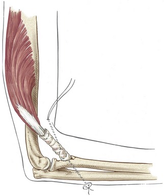
An important mechanical trade-off exists whenever a muscle’s MA is surgically increased. Although a greater torque is produced per level of muscle force, a given amount of muscle shortening results in a reduced angular displacement of the joint. As a result, a full muscle contraction may produce an ample torque, but the joint may not complete its full range of motion.6 In essence, the active range of motion “lags” behind the muscle contraction. The reduced displacement and velocity of the distal segment of the joint may have negative functional consequences. This mechanical trade-off needs to be considered before the muscle’s internal moment arm is surgically enhanced. Often, the greater torque potential gained by increasing the moment arm functionally “outweighs” the loss of the speed and distance of the movement.
GLOSSARY
Acceleration: change in velocity of a body over time, expressed in linear (m/sec2) and angular (degrees/sec2) terms.
Accessory movements: slight, passive, nonvolitional movements allowed in most joints (also called joint play).
Active force: push or pull generated by stimulated muscle.
Active movement: motion caused by stimulated muscle.
Agonist muscle: muscle or muscle group that is most directly related to the initiation and execution of a particular movement.
Anatomic position: the generally agreed on reference position of the body used to describe the location and movement of its parts. In this position, a person is standing fully upright and looking forward, with arms resting by the side, forearms fully supinated, and fingers extended.
Angle-of-insertion: angle formed between a tendon of a muscle and the long axis of the bone into which it inserts.
Antagonist muscle: muscle or muscle group that has the action opposite to a particular agonist muscle.
Arthrokinematics: motions of roll, slide, and spin that occur between curved articular surfaces of joints.
Axial rotation: angular motion of an object in a direction perpendicular to its longitudinal axis; often used to describe a motion in the horizontal plane.
Axis of rotation: an imaginary line extending through a joint around which rotation occurs (also called the pivot point or the center of rotation).
Bending: effect of a force that deforms a material at right angles to its long axis. A bent tissue is compressed on its concave side and placed under tension on its convex side. A bending moment is a quantitative measure of a bend. Similar to a torque, a bending moment is the product of the bending force and the perpendicular distance between the force and the axis of rotation of the bend.
Center of mass: point at the exact center of an object’s mass (also referred to as center of gravity when considering the weight of the mass).
Close-packed position: unique position of most joints of the body where the articular surfaces are most congruent and the ligaments are maximally taut.
Compliance: the inverse of stiffness.
Compression: a force, applied perpendicularly to the contact surface, that pushes or pulls one object directly against another.
Concentric activation: activated muscle that shortens as it produces a pulling force.
Creep: a progressive strain of a material when exposed to a constant load over time.
Degrees of freedom: number of independent directions of movements allowed at a joint. A joint can have up to three degrees of translation and three degrees of rotation.
Displacement: change in the linear or angular position of an object.
Distal-on-proximal segment kinematics: type of movement in which the distal segment of a joint rotates relative to a fixed proximal segment (also called an open kinematic chain).
Distraction: a force, applied perpendicularly to the contact surface, that pushes or pulls one object directly away from another.
Eccentric activation: activated muscle that is producing a pulling force while being elongated by another more dominant force.
Elasticity: property of a material demonstrated by its ability to return to its original length after the removal of a deforming force.
External force: push or pull produced by sources located outside the body. These typically include gravity and physical contact applied against the body.
External moment arm: perpendicular distance between an axis of rotation and the external force.
External torque: product of an external force and its external moment arm (also called external moment).
Force: a push or a pull that produces, arrests, or modifies a motion.
Force-couple: two or more muscles acting in different linear directions, but producing a torque in the same rotary direction.
Force of gravity: potential acceleration of a body toward the center of the earth as a result of gravity.
Friction: resistance to movement between two contacting surfaces.
Internal force: push or pull produced by a structure located within the body. Most often, internal force refers to the force produced by an active muscle.
Internal moment arm: perpendicular distance between the axis of rotation and the internal (muscle) force.
Internal torque: product of an internal force and its internal moment arm.
Isometric activation: activated muscle that maintains a constant length as it produces a pulling force.
Joint reaction force: force that exists at a joint, developed in reaction to the net effect of internal and external forces. The joint reaction force includes contact forces between joint surfaces, as well as forces from any periarticular structure.
Kinematics: branch of mechanics that describes the motion of a body, without regard to the forces or torques that may produce the motion.
Kinematic chain: series of articulated segmented links, such as the connected pelvis, thigh, leg, and foot of the lower extremity.
Kinetics: branch of mechanics that describes the effect of forces and torques on the body.
Leverage: relative moment arm length possessed by a particular force.
Line of force: direction and orientation of a muscle’s force.
Line of gravity: direction and orientation of the gravitational pull on a body.
Load: general term that describes the application of a force to a body.
Longitudinal axis: axis that extends within and parallel to a long bone or body segment.
Loose-packed positions: positions of most synovial joints of the body in which the articular surfaces are least congruent and the ligaments are slackened.
Mass: quantity of matter in an object.
Mechanical advantage: ratio of the internal moment arm to the external moment arm.
Moment arm: perpendicular distance between an axis of rotation and the line of force.
Muscle action: potential of a muscle to produce a torque within a particular plane of motion and rotation direction (also called joint action when referring specifically to a muscle’s potential to rotate a joint). Terms that describe a muscle action are flexion, extension, pronation, supination, and so forth.
Osteokinematics: motion of bones relative to the three cardinal, or principal, planes.
Passive force: push or pull generated by sources other than stimulated muscle, such as tension in stretched periarticular connective tissues, physical contact, and so forth.
Passive movement: motion produced by a source other than activated muscle.
Plasticity: property of a material demonstrated by remaining permanently deformed after the removal of a force.
Pressure: force divided by a surface area (also called stress).
Productive antagonism: phenomenon in which relatively low-level tension within stretched connective tissues performs a useful function.
Proximal-on-distal segment kinematics: type of movement in which the proximal segment of a joint rotates relative to a fixed distal segment (also referred to as a closed kinematic chain).
Roll: arthrokinematic term that describes when multiple points on one rotating articular surface contact multiple points on another articular surface.
Rotation: angular motion in which a rigid body moves in a circular path around a pivot point or an axis of rotation.
Scalar: quantity, such as speed or temperature, that is completely specified by its magnitude and has no direction.
Segment: any part of a body or limb.
Shear: a force produced as two compressed objects slide past each other in opposite directions (like the action of two blades on a pair of scissors).
Shock absorption: the act of dissipating a force.
Slide: arthrokinematic term describing when a single point on one articular surface contacts multiple points on another articular surface (also called glide).
Spin: arthrokinematic term describing when a single point on one articular surface rotates on a single point on another articular surface (like a top).
Static linear equilibrium: state of a body at rest in which the sum of all forces is equal to zero.
Static rotary equilibrium: state of a body at rest in which the sum of all torques is equal to zero.
Stiffness: ratio of stress (force) to strain (elongation) within an elastic material, or N/m (also referred to as Young’s modulus or modulus of elasticity).
Strain: ratio of a tissue’s deformed length to its original length. May also be expressed in units of distance (m).
Stress: force generated as a tissue resists deformation, divided by its cross-sectional area (also called pressure).
Synergists: two or more muscles that cooperate to execute a particular movement.
Tension: application of one or more forces that pulls apart or separates a material (also called a distraction force). Used to denote the internal stress within a tissue as it resists being stretched.
Torque: a force multiplied by its moment arm; tends to rotate a body or segment around an axis of rotation.
Torsion: application of a force that twists a material around its longitudinal axis.
Translation: linear motion in which all parts of a rigid body move parallel to and in the same direction as every other point in the body.
Vector: quantity, such as velocity or force, that is completely specified by its magnitude and direction.
Velocity: change in position of a body over time, expressed in linear (m/sec) and angular (degrees/sec) terms.
Viscoelasticity: property of a material expressed by a changing stress-strain relationship over time.
REFERENCES
1. Akeson, WH, Amiel, D, LaViolette, D, et al. The connective tissue response to immobility: an accelerated ageing response? Exp Gerontol. 1968;3:289–301.
2. Belisle, AL, Bicos, J, Geaney, L, et al. Strain pattern comparison of double- and single-bundle anterior cruciate ligament reconstruction techniques with the native anterior cruciate ligament. Arthroscopy. 2007;23:1210–1217.
3. Beynnon, BD, Fleming, BC. Anterior cruciate ligament strain in-vivo: A review of previous work. J Biomech. 1998;31:519–525.
4. Beynnon, BD, Fleming, BC, Johnson, RJ, et al. Anterior cruciate ligament strain behavior during rehabilitation exercises in vivo. Am J Sports Med. 1995;23:24–34.
5. Brand, PW. Clinical biomechanics of the hand. St Louis: Mosby; 1985.
6. Brand, PW. The reconstruction of the hand in leprosy. Clin Orthop Relat Res. 2002;396:4–11.
7. Debski, RE, Weiss, JA, Newman, WJ, et al. Stress and strain in the anterior band of the inferior glenohumeral ligament during a simulated clinical examination. J Shoulder Elbow Surg. 2005;14:24S–31S.
8. Dvir, Z. Clinical biomechanics. Philadelphia: Churchill Livingstone; 2000.
9. Fleming, BC, Oksendahl, H, Beynnon, BD. Open- or closed-kinetic chain exercises after anterior cruciate ligament reconstruction? Exercise Sport Sci Rev. 2005;33:134–140.
10. Graichen, H, Englmeier, KH, Reiser, M, Eckstein, F. An in vivo technique for determining 3D muscular moment arms in different joint positions and during muscular activation—application to the supraspinatus. Clin Biomech (Bristol, Avon). 2001;16:389–394.
11. Hashemi, J, Chandrashekar, N, Mansouri, H, et al. The human anterior cruciate ligament: Sex differences in ultrastructure and correlation with biomechanical properties. J Orthop Res. 2008;26:945–950.
12. Ireland, ML, Willson, JD, Ballantyne, BT, Davis, IM. Hip strength in females with and without patellofemoral pain. J Orthop Sports Phys Ther. 2003;33:671–676.
13. Keller, TS, Spengler, DM, Hansson, TH. Mechanical behavior of the human lumbar spine. I. Creep analysis during static compressive loading. J Orthop Res. 1987;5:467–478.
14. Kolt, SK, Snyder-Mackler, L. Physical therapies in sport and exercise. Philadelphia: Churchill Livingston; 2003.
15. Ledoux, WR, Blevins, JJ. The compressive material properties of the plantar soft tissue. J Biomech. 2007;40:2975–2981.
16. Little, JS, Khalsa, PS. Material properties of the human lumbar facet joint capsule. J Biomech Eng. 2005;127:15–24.
17. Lu, XL, Mow, VC. Biomechanics of articular cartilage and determination of material properties. Med Sci Sports Exerc. 2008;40:193–199.
18. Lundon, K. Orthopaedic rehabilitation science: principles for clinical management of nonmineralized connective tissue. St Louis: Butterworth-Heinemann; 2003.
19. McNamara, LM, Prendergast, PJ, Schaffler, MB. Bone tissue material properties are altered during osteoporosis. J Musculoskelet Neuronal Interact. 2005;5:342–343.
20. Mellor, R, Hodges, PW. Motor unit synchronization of the vasti muscles in closed and open chain tasks. Arch Phys Med Rehabil. 2005;86:716–721.
21. Michlovitz, SL. Thermal agents in rehabilitation, ed 3. Philadelphia: FA Davis; 1996.
22. Neumann, DA. Arthrokinesiologic considerations for the aged adult. In Guccione AA, ed.: Geriatric Physical Therapy, ed 2, Chicago: Mosby, 2000.
23. Nordin, M, Frankel, VH. Basic biomechanics of the musculoskeletal system, ed 2. Philadelphia: Lea & Febiger; 1989.
24. Panjabi, MM, White, AA. Biomechanics in the musculoskeletal system. New York: Churchill Livingstone; 2001.
25. Perry, MC, Morrissey, MC, King, JB, et al. Effects of closed versus open kinetic chain knee extensor resistance training on knee laxity and leg function in patients during the 8- to 14-week post-operative period after anterior cruciate ligament reconstruction. Knee Surg Sports Traumatol Arthrosc. 2005;13:357–369.
26. Pigeon, P, Yahia, L, Feldman, AG. Moment arms and lengths of human upper limb muscles as functions of joint angles. J Biomech. 1996;29:1365–1370.
27. Standring, S. Gray’s anatomy: the anatomical basis of clinical practice, ed 40. St Louis: Elsevier; 2009.
28. Stromberg, DD, Wiederhielm, CA. Viscoelastic description of a collagenous tissue in simple elongation. J Appl Physiol. 1969;26:857–862.
29. Szerb, I, Karpati, Z, Hangody, L. In vivo arthroscopic cartilage stiffness measurement in the knee. Arthroscopy. 2006;22:682.
30. Withrow, TJ, Huston, LJ, Wojtys, EM, et al. Effect of varying hamstring tension on anterior cruciate ligament strain during in vitro impulsive knee flexion and compression loading. J Bone Joint Surg Am. 2008;90:815–823.
31. Woo, SL, Gomez, MA, Woo, YK, et al. Mechanical properties of tendons and ligaments. II. The relationships of immobilization and exercise on tissue remodeling. Biorheology. 1982;19:397–408.
32. Woo, SL, Matthews, JV, Akeson, WH, et al. Connective tissue response to immobility. Correlative study of biomechanical and biochemical measurements of normal and immobilized rabbit knees. Arthritis Rheum. 1975;18:257–264.
STUDY QUESTIONS
1. Contrast the fundamental difference between kinematics and kinetics.
2. Describe a particular movement of the body or body segment that incorporates both translation and rotation kinematics.
3. Note the accessory movements at the metacarpophalangeal joint of your index finger in full flexion and in full extension. Which is greater? Which position (flexion or extension) would you assume is the joint’s close-packed position?
4. Figure 1-8 depicts the three fundamental movements between joint surfaces for both convex-on-concave and concave-on-convex arthrokinematics. Using a skeleton or an image of a skeleton, cite an example of a specific movement at a joint that matches each of these six situations. Examples may include combinations of roll and slide.
5. Provide examples of how the six forces depicted in Figure 1-12 could naturally occur at either the disc or spinal cord associated with the junction of the fifth and sixth cervical vertebrae.
6. Contrast the fundamental differences between force and torque. Use each term to describe a particular aspect of a muscle’s contraction relative to a joint.
7. Define and contrast internal torque and external torque.
8. The elbow model in Figure 1-17 is assumed to be in static equilibrium. While maintaining this equilibrium, how would a change in the variables EF, D1, or D independently affect the required amount of internal force (IF)? How can a change in these variables “protect” an arthritic joint from unnecessarily large joint reaction forces?
9. Slowly lowering a book to the table uses an eccentric activation of the elbow flexor muscles. Explain how changing the speed at which you lower the book can affect the type of activation (e.g., eccentric, concentric) and choice of muscle.
10. Assume a surgeon performs tendon transfer surgery to increase the internal moment arm of a particular muscle relative to a joint. Are there potential negative biomechanical consequences of increasing the muscle’s moment arm (leverage) too far? If so, please explain.
11. Describe a possible pathologic situation in which the inferior-directed joint reaction force (JRF) depicted in Figure 1-15, B is not able to be generated by the distal humerus.
12. What is the difference between force and pressure? How could these differences apply to protecting the skin of a patient with a spinal cord injury and reduced sensation?
13. Describe the difference between mass and weight.
14. Most muscle and joint systems within the body function as third-class levers. Cite a biomechanic or physiologic reason for this design.
15. Assume a patient developed adhesions with marked increased stiffness in the posterior capsular ligaments of his knee. How would this change in tissue property affect full passive range of motion at the joint?
 Answers to the study questions can be found on the Evolve website.