“Very” Future Directions in Minimally Invasive Spinal Surgery

Published on 17/03/2015 by admin

Filed under Orthopaedics

Last modified 22/04/2025

Print this page

rate 1 star rate 2 star rate 3 star rate 4 star rate 5 star
Your rating: none, Average: 0 (0 votes)

This article have been viewed 1248 times

CHAPTER 61 “Very” Future Directions in Minimally Invasive Spinal Surgery

(Note to the reader: In order to describe the future directions of minimally invasive spinal surgery, a case performed in 2022 is described. All the technology described as follows is available today.)

It’s difficult to say exactly what day you become a surgeon, but you’re probably born sometime during your residency. Given this birth date, I can say that I’ve been operating for 40 years. I entered my third year of residency in July of 1982, and here it is today, July of 2022.

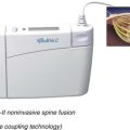
It’s even more difficult to call what I’m doing now surgery. When they opened the Techno-Suite 2 years ago, I took over the remote console pretty much full time (Fig. 61–1), and the residents worked the “Pit.” That’s the macho nickname for the sterile area. Compared with the old spinal surgery operating rooms I used to work in, the so-called Pit is pretty tame. Getting blood on the floor nowadays almost calls for an incident report, unlike back in the day, when you always saw the mop and bucket come out after a spinal fusion. Probably the biggest culture shift is the cast of characters needed to pull off a spinal case; the Pit is no longer the dominion of the solitary alpha male, perpetually irritated spinal surgeon, but rather looks like the clean room at NASA, where they assemble the Mars modules. Actually looking through the glass into the Pit now, I can’t even see a surgeon.
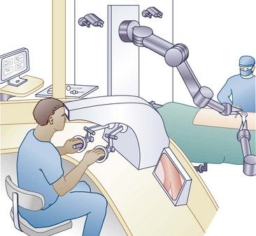
The robot-guy (as he’ll forever be known), Brad, is draping out the two robotic arms, #1 and #2. Each arm is about 6 feet long and is mounted on tracks that go up and down the length of the pit. On the far track is #2, and on the near track is #1. Between them, they get 360-degree access to the patient. Their “park” position is at the foot of the table, where Brad can change out their end manipulators. Although they’re designed to move within the operative space, I can also operate them with the two haptic handpieces right behind me on the console.

Brad works in the Pit with Gordon, the virtual planner. We submitted the work plan last week to give Gordon enough time to show us what the surgery should look like when we’re done and to sequence all the tools and implants before they were sterilized. Gordon will also continually update the virtual image during surgery to ensure its accuracy. Actually, reviewing the plan on my phone this morning, it looks like this first case is a five-part, complex restoration. The patient today has end-stage disc degeneration at L5-S1, with an early spondylolisthesis and stenosis at L4-L5. We did a metabolic survey of the L3-L4 disc and it still may be salvageable with a reconstitution, so we’ll tack that on at the end. It’s unusual that people let their backs get this bad nowadays. A four-part restoration takes about 4 hours, which by today’s standards is a pretty big case.

Tonya is the new biomodulator technologist. She brings in all the potions that we’ll be putting in the pumps and handles the electroactive implants. She’s taking the plasmids out of deep freeze and sequences the factors. She knows all the formulas: factors II and VII early, factor IX late for de novo bone, and pumping VEGF (vascular endothelial growth factor) in before the chondrocytic plasmids. That’s not even mentioning some of her epidural pain concoctions. We couldn’t do the surgery without her. On a four-part restoration we’ll be doing both plasmids and factors and then mechano-modulation at the end. As soon as we get started, she’ll prefill the pumps before we put them in.

The actual surgical technologist is setting up the soft tissue area. The old-style back table has dwindled down to a scalpel, a bovie, and set of soft tissue dilators. With the subdermal, absorbable zip ties and epidermal adhesives, there isn’t a suture to be seen. People are actually requesting that they get the robotic skin closure.

Preparation

Well, here come the traditional players into the suite: the circulator, the anesthesiologist, the resident, and of course, the patient. This may be the last traditional-looking scene that happens today; after this, it gets a little unconventional. So far, nothing special is going on. They’ll do the intubation, the IVs, and the Foley catheter. Once the patient is ready for positioning, the resident and I have to recite the Hippocratic Oath as part of the new time-out procedure.

To get the patient articulated into the 3-D (three-dimensional) universal spine positioner, the limb, pelvic, chest, and head shells need to be put on. The head shell looks just like a full-contact motorcycle helmet. The anesthesiologist takes charge of getting that into place and hooking up the helmet’s pressure insufflations, tubes, and sensors. The resident and circulator start at the patient’s feet and start placing the boots and thigh cuffs on, making sure the pressure tubes and sensors are connected. The sacral and iliac pads form the pelvic ring. It’s the hardest to place and done next. I’m starting to get the pressure sensor signals up on my monitor, and so far all the pieces are insufflating and beginning to cycle the pressure points appropriately. Finally, the chest vest and arm pieces are in place and the actual positioner can be hooked up.

Although it’s every bit as sophisticated as our operative robots, we still call the positioner the “table.” The last mechanical vestige of a table is the connecting bridge between the chest vest and the pelvic ring, only because it connects and supports the upper and lower body. After the draping skirts are placed around the patient, the 3-D positioner itself comes in like two jousting forklifts with the patient in the middle. The left and right sides of the lower body are attached to each arm of the lower positioner, and the upper torso is clipped on to the upper positioner. The helmet is held by the upper positioner with a separate passive arm. The resident connects the active link between the chest vest and the pelvic ring and gives me the “high” sign to begin turning the patient. All the pressure sensors are recording, so the positioner accepts the patient by accepting the weight and the gurney simply slides out from underneath the patient. David Copperfield would have been proud. We’ll be doing mainly posterior and lateral approaches today, so I turn on the patient positioning warning light and begin the rotation to prone.

Now that we’re prone, it’s time to start the process. The circulator preps the trunk circumferentially, while the resident goes out and scrubs his hands. Brad puts the fluoroscopic receiver on #2 and the transmitter on #1. By this time the draping skirts have been opened and unrolled, and the positioner is covered.

Identifying and Tagging the Anatomy

As the resident dons his lead, I reflexively look up at the ceiling at the tracking cameras that surround the Pit. They’re all on, making you feel like you’re under surveillance … technically you are. The ceiling cameras create a seamless optical environment. Just like a surveillance camera following a criminal, if you block one, you’ll still be seen on one of the others. With the #1 and #2 on simple tracking mode, the resident holds the EM (electromagnetic) gun over the patient. The gun is being optically followed by both #1 and #2. As the resident moves the gun down toward the pelvis, the robotic arms follow the gun like two enthralled spectators, one looking from above and one looking from below. There are 10 EM coil emitters preloaded into the gun. Each has a short tacklike tip that fixes it into the bone. Each coil emitter has a unique signal, based on its distance from, and orientation to, a magnetic field. Each coil trails from it a thin wire that communicates to the navigation system. The gun is steadied over the pelvis, and a light touch of the trigger produces an image of the iliac crest on all the screens hanging in the techno-suite, as well as my monitor screen on the console. Looks like it’s a good spot—the resident makes a stab incision, pushes the gun down against the crest, and fires the 5-mm-long EM coil sensor onto the crest. Next up is the L5 vertebra. The fluoro shots on my monitor show him lining up the gun on top of the spinous process and firing a coil emitter into L5. He goes ahead and places a coil emitter on L4 and L3 as well. To make these trackable, Brad goes under the table and attaches the EM field generator and then attaches each of the coil emitter wires into the switch box.

It’s time for the robotic dance. A fluoroscopic receiver is placed on one arm and a transmitter is mounted on the other robotic arm. Each arm has its own EM sensor, so not only do we know where the arms are within the EM field but, more importantly, we can know where the images (by virtue of their attached emitter coils) are within the EM field as well. We locate the anatomic center of the operative field. I push the automatic movement mode and the red flashing lights come on. Autonomous robotic motion always has to be done under alert conditions as dictated by the FDA (U.S. Food and Drug Administration) robotic guidelines. While #1 goes above the patient with the transmitter, #2 goes below with the receiver. They begin at the top of the operative field. Each one spins in a nearly 180-degree arc, one above and one below the patient. By staying “isocentric” to the patient and moving slowly down the length of the target anatomy, complete cross-sectional imaging of the operative field is obtained.

I check the images on my console and assemble them into the 3-D model. There’s always a fair amount of noise in the OR (operating room) images, so I pull up the preoperative plan that Gordon gave us and tease out the naked CT (computed tomography) scan. By merging the preoperative scan with the intraoperative scan, it cleans up nicely.

It’s time to tell the optical tracking cameras where each emitter coil lies on the pelvis and vertebrae. Whenever we begin to address a specific spinal segment, we “find” it optically first by using a detector that has its own EM detector and an optical array. When the detector’s sensor coil recognizes its relation to the implanted spinal segment sensor coil in the EM field, the image of the attached spinal segment will be precisely located by the optical cameras as well. This accomplishes two goals. First, standard, optically tracked instruments can be used for the rest of the procedure, and second, each spinal segment is continually tracked within the EM field even if breathing, patient motion, surgical manipulation, and so on cause them to move from their original position. Emitter coil placement and image acquisition placement to registration took 17 minutes, 43 seconds.

Part I: Transalar Fusion L5-S1

We’ll start from the bottom (literally) and work up. I notice out of the corner of my eye that everyone in the pit is getting ready. Brad is taking the cameras off of the robotic arms, while Gordon is bringing up the plans that will let us drill a 7.5-mm tunnel on each side of the iliac crest, up the sacral ala, and then across the L5-S1 disc. The plans are now up and I give them official approval. The robotic arms are outfitted with the drill and drill guide.

The resident reconfirms the position of the pelvis with the EM detector, and #2, following the preop plans, points to the entry point where the trajectory of the pathway crosses the skin. I watch the resident make the skin incision, then turn and keep track of the virtual world on my monitor. Through this I watch the drill guide go down the access portal, followed by the drill going down the drill guide. Because robotic policy requires passive drilling, the resident manually presses the drill forward. I watch it on the screen and also monitor the drill pressure through sensors. Pressure goes up as the drill goes through the iliac crest and then drops as it crosses the sacrospinous space. Drill pressure sensing while watching the progress of the virtual drill is a nice reality check. I tell the resident that he’s in the L5-S1 disc. He then does the other side. The robotic arms pull back, Brad switches the end actuators back to the fluoro mode, and they come back in for a reality fluoro check.

Once drill position is confirmed, Brad reoutfits the end actuators. #1 gets the reamer, #2 gets the tube retractor holder. The reamer is placed into the tissue protector, and the tunnel to the disc is reamed. I watch the virtual instruments as they enter the disc on the console: the reamer, the curettes, and even the pituitaries have their graphic counterparts on my screen. Tonya, on cue, starts putting the filled bone tubes with the loading BMP dose on her ready table. The resident manually fills the disc with the graft, while Brad outfits #2 with the implants. These are the new biointegrated implants, so Tonya is getting the biomodulation pump ready. Tonya would like the left implant to be infused by the pump, and Brad hooks up the catheter from the implant to the first infusion port on the pump. Number 1 threads the cages across the L5-S1 disc space, carefully positioning them so that they can later be connected to a rod system. Tonya, meanwhile, loads the pump’s reservoirs with BMPs (bone growth factors), FGFs (fibrous growth factors), VEGFs (vascular endothelial growth factors), and chondrocytic plasmids that will be infused into their target discs postoperatively. She activates portal 1 on the pump and confirms that BMP is flowing into the implant. The resident now does the first thing that actually resembles surgery, creating a subcutaneous pouch.

Our time’s not bad. Lumbosacral implants with pump in took 47 minutes.

Part II: L4-5 Fibroregeneration

Like a huge rotisserie, the patient is slowly rotated into the side-lying position as we start the intradiscal part for L4-5. We’ve gone back and forth about grade I degenerative spondylolistheses for years: various combinations of decompression, fusion, and dynamic stabilization. The present fashion is to do a limited decompression (which we’ll do in about an hour) but try to salvage some more lifetime out of the disc through fibrogenesis. As long as the annulus is competent and there’s no endplate edema, if we can restore some viable, intradiscal, collagenous tissue, we can get a stable, asymptomatic level.

Brad puts the guided, endoscopic dissecting portal on the robotic arm, while the resident does the optical/EM correlation to let us track L4 and L5. Obviously, with the manipulation at L5-S1 and the change in patient position, the vertebrae have moved from their original position. First the image of L5 pops up on my console, then L4 as each segment is reregistered. I draw the trajectory to the disc space from the entry point on the left flank. It’s a tough job, but somebody has to do it.

The lights flash as the robotic arm moves to the plan I just supplied and uses the laser to point to where the lateral incision should be made. The resident dutifully makes a small incision on the red spot. Exactly on cue, as the #2 arm moves out, the #1 arm brings the portal into position. I enjoy this portion as the endoscopic view pops up on my console screen. I’m looking through the tip of the portal as it enters the subcutaneous tissue. This is where I feel like I’m operating again, but instead of spreading and cutting, I use portal functions to get through the tissue. In the subcutaneous fat, simple x- and y-axis oscillations usually get me down to the oblique muscles, as I see the pale yellow fat push out of the way and the view changes to a brown-maroon.

At the obliques I find it helpful to turn on the ultrasonic function, especially as my indicators show a rising forward pressure. When there is a sudden decline in that pressure, I know I made it through the muscle’s fascia. The tip of the endoscopic can be oscillated to help the dissection through the muscle layers. When I finally see the sudden change from the white fascia of the transversalis to the deep yellow of the retroperitoneum, I know we’re in the right spot. I check the navigation image, and the virtual scope is about 7 cm from the L4-L5 disc.

This fat is miserable to work with, even back when we used retractors, but the balloons make the process tolerable. I repeatedly inflate the balloon collar around the guided portal and then advance, keeping an eye on the endoscopic view from the tip of the portal. The psoas comes into view, and the scope oscillates and rotates to dissect through as I check progress on the navigation screen. There, we’ve docked on the L4-L5 disc; the endoscope shows the milky colored disc surface, and the navigation screen confirms the position of the (virtual) endoscope on the lateral side of the L4-L5 disc.

The portal holding arm, #1, is indefatigable as it continues to hold the portal against the disc surface using navigation to keep it in just the right position. I signal the resident to start the fibroregeneration process. He pulls out the fiber optic lens and its clear plastic portal window, leaving the sleeve as our working cannula. We first have to remove the central nucleus. Through a simple 5-mm puncture in the annulus, the resident introduces the articulated nucleotomy aspirator. This just takes 5 minutes, and then it comes out. Because we want to repopulate this space with viable fibrous tissue, we have to first re-establish a viable blood supply in the disc. The required multiple endplate perforations to do this are done from the inside out because there are no sensitive cellular tissues to protect. The resident takes the aspirator out and puts the guided, right-angled endplate perforator into the disc. Because this, too, shows up on my screen, I help him get a nicely dispersed pattern of perforations on the superior and inferior endplates. While this is going on, Tonya is bringing up the preloaded allograft collagen tubes for impaction into the mesh containment bag.

The resident pulls the perforator out and inserts the mesh containment bag into the perforated disc space. Here’s where we go “old school” again, as the resident uses a hammer to fill the mesh with collagen; it looks like it’ll take a couple of tubes. Tonya talks the resident through disconnecting the loading tube and connecting the catheter that runs from the collagen-filled bag in the disc to the second port on the BMP. This, of course, is hooked up to the FGF and VEGF reservoirs. These factors, when placed in a collagen milieu with viable progenitor cells and placed under appropriate mechanical stress (as shown later), will repopulate the disc with metabolically active fibrocytes.

The catheter is tunneled subcutaneously to the pump, the portal attached to #2 is withdrawn, and I check the time: we got that done in 34 minutes, which puts our running total at 1 hour 51 minutes. We’ve got one more disc to biologically alter and then we’ll flip back around for the “mechanical solutions.”

Part III: Chondrogenic Reconstitution

The next target is the L3-L4 disc. Its PET (positron emission tomography) scan showed virtually no metabolic activity in the native chondrocytes and, of course, the early dehydration on the MRI (magnetic resonance imaging). We’re going to “pin cushion” both of the endplates with microdrills, from the outside/in, to get some progenitor cells into the nucleus, and then serve them up a steady diet of plasmids to stimulate them to produce a more plentiful extracellular matrix.

The patient is rotated back to the prone position, and the resident updates the optical/EM correlation at the L3-L4 level. Brad is pulling the endoscope off of #1 and putting the needle-like microdrill guide on, which he’ll enter in the software. I’m reviewing the 12 to 18 microdrill trajectory lines into the L3-L4 disc that Gordon had set up. I’m thankful for preoperative planning. If I had to align each one of these by hand, not only would we be here all day but I would lose my mind; it’s bad enough having to review these trajectories.

To drill into the L3-L4 disc we basically dock on the inferior margin of each of the L4 pedicles and angle upwards and into the disc at four or five different locations. Then we dock at the base of the superior margin of the L3 pedicle and angle downward into the L3-L4 disc, again making four or five passes. The drill diameter is 0.5 mm, which allows this to be done through needle sticks as opposed to a separate incision.

From the plans it looks like the average drill length is about 47 mm. The resident adjusts the length of the microdrill guide and we get started. #1 moves right over the first trajectory and then goes into passive mode. The resident pushes it down until it contacts the skin. The needle-like tip penetrates the skin, and the microdrill guide is advanced farther into the posterior musculature until it contacts bone. The resident passes the drill down the cannula and drills a small perforation into the L3-L4 disc. We always get fluoroscopic confirmation of the first drilling trajectory. Brad has put the fluoroscopic transmitter on #2, which is now pointed upward from underneath the table. The resident holds the optically tracked, handheld receiver plate over the top of the patient. We shoot an image, and my monitor reads 99.9% correlation between the actual fluoroscopic image and the virtual representations. One down, 17 to go. Number 1 is pulled out and then moves dutifully to the next site. We repeat this 18 times, through both the upper and lower endplates.

With a potentially more viable environment within the disc and an avenue for pluripotential cells to find their way into the disc, it’s time for the biomodulators. We’ll use the same microdrill sleeve to enter the disc. I draw a final trajectory, which leads to what we used to call Kambin triangle. The resident pierces the disc with the sleeve and inserts the needle into the middle of L3-L4. The catheter is threaded into the disc and left in place. This catheter is then tunneled back to the BMP and hooked up to the reservoir containing the plasmids. A percentage of the primitive cells that migrate into the disc will phagocytose these genetic fragments and begin producing extracellular ground substance.

At this point, we’ve basically completed the biologic portions of the procedure. L5-S1 has been prepared for bone formation, L4-L5 has been prepared for fibrous tissue, and L3-L4 is going to be repopulated with chondrocytes. Two basic steps remain: decompress the L4-L5 stenosis and then alter the mechanobiology of the discs with our pedicle-based systems.

Part IV: L4-L5 Spinal Decompression

To perform a bilateral compression at the L4-L5 level, we can get to both sides through a single midline incision. The key is that the L4 spinous process overlies the L4-L5 disc space. The L4 spinous process can be a natural corridor that leads to the L4-L5 interlaminar space. The resident correlates the optical/EM position of L4 and L5 and then removes the EM tracker embedded in the L4 spinous process and reimplants it, under guidance, to the L4 superior articular process. While he’s doing that, I’m reviewing the cross-sectional images and bringing up the preoperative plan with the target area for decompression: mainly the top of the L5 lamina, the bottom of the L4 lamina, the ligamentum flavum, and both L5 lateral recesses. Once again I approve it without modifications, meaning that Gordon’s decompression algorithms are perfect again. Meanwhile, Brad reoutfits #1 with the guided high-speed bur, while #2 gets the retractor mechanism, which consists of two flat retractor blades that can open up to 22 mm in diameter.

In the passive mode, the #1 robotic arm now becomes something like one of those Border Collies that inexorably herds the sheep toward the gate. It is outfitted with the navigated bur but only moves when the resident manipulates it. As long as the resident moves the arm with the attached drill toward the target area that I have colorized, the arm moves smoothly and freely. But should the resident try to move the arm away from the colorized L4 spinous process, the arm immediately brakes, giving a sensation similar to bumping into a solid wall. He is compelled to bring the drill only to the L4 spinous process. Not only is the purpose of the robotic arm to bring the drill “to” the L4 spinous process, it is more importantly designed to keep the drill “within” the spinous process. The colorized area establishes a boundary, through which the robotic arm will not allow the drill to pass: the “no fly zone.” The robotically tethered drill can move within the confines of the L4 spinous process and the lamina but cannot broach the cortex on the interior side of the lamina nor go out laterally through the pars interarticularis.

The resident makes a 2-cm incision over the tip of the L4 spinous process and passively positions the retractor into the incision. He hooks up the fiberoptic cable, and the view of the lumbar fascia comes into view on my console screen. I watch as the resident exposes the top of the process. He grabs the #1 robotic arm with the navigated bur and advances toward the tip of the L4 spinous process. As the bur goes to work it begins to split the spinous process down the middle. I glance at the virtual L4 image on my console. The colorized bone is slowly disappearing on the computerized L4 representation. I check the view on the endoscope in the retractor, and the drill is at the depth that correlates with the bone disappearing. The split is now deep enough to splay the two halves apart. The #2 arm delivers the retractor into the split spinous process, and the blades plastically deform each cortex until they are about 14 mm apart. The drill in #1 re-enters the retractor and resumes the drilling; now heading out laterally as it enters the lamina proper. I watch the whole process on my console. The real-time endoscopic view is in the upper right corner of my screen, while the virtual bone is being wiped away by the virtual drill on my navigation screen. Basically, anytime the drill tip intersects the 3-D space where a bone density pixel used to lie, the computer deletes that pixel from the image. The drill is staying perfectly within the “no fly zone” indicated by the anatomic boundaries I drew. In fact, right now the resident is bouncing off of the cortex adjacent to the thecal sac. In reality he is being prevented by the robotic arm from entering the spinal canal, but the sensation is that he is bouncing off the bone itself. This is my signal to increase the permissible operating boundary by 2 mm as we switch to the Kerrison rongeur. The Kerrison is used freehand but is optically tracked. Its virtual representation pops up on my screen. The added area permits the Kerrison to enter underneath the remaining bony shell and finish off the remaining bony edges. As I watch the bone disappear with each bite, I notice that the resident is not going out laterally enough. I get the resident to change the inclination of the retractor and the lateral recess comes into view. The resident can now reach farther out laterally and fully decompress both lateral recesses.

With the completion of the decompression, we return the robotic arms and start gearing up for the last portion of the procedure, the posterior mechanical environment.

Part V: Posterior Mechanical Environment

It’s time to integrate all three levels together with our posterior mechanical system. In order to build a posterior system that connects with the implants that have been positioned in L5-S1, we’ll go ahead and rescan all four vertebral segments. Brad has already reconvened #1 and #2 at the head of table and taken the drill and retractor off. Now he’s outfitting them with their fluoroscopic heads. Gordon has loaded the pedicle planning pathways, as well as the docking algorithms, to articulate with the transalar implants. We just need the new intraoperative scan to place them on. Right on cue, #1 and #2 re-enter the operative area, the red flashing lights come on, and the patient is rescanned.

Meanwhile, Tonya is cleaning up the molecular biomodulators and getting the physical mechano-modulators ready. We’ve recently gotten the whole biomodulation system integrated into one implantable power source where the battery that runs the reservoir can also be used to power the electroactive rod system. This case is, in fact, a three-level solution where the mechanical environment is different at each level. For L5-S1 the old standard mechanical environment of rigid fixation is being created. In this case, we’ll enhance the fixation by anchoring the posterior rod system into L5-S1 implants themselves rather than direct bony fixation.

Whereas rigid fixation is required for L5-S1, an entirely different biophysical signal is necessary at L4-L5, where we want to encourage fibrous tissue growth. Here the posterior system will create a constant tension force through a dynamic spring implant. Finally, L3-L4 is the latest in mechano-modulation with electroactive polymer rods creating the continuous motion required for chondrocytic differentiation. These require the power supply that Tonya is getting ready. Finally, the screws themselves are the watchdogs of the system. Each screw has a radiofrequency microtensiometer mounted on the head and on the shaft. These can be locally and individually scanned to indicate the forces that both the rods and screws are experiencing. They’ll stay active for up to 2 years after implantation.

Brad indicates that the navigation scan is completed, and the robotic arms retreat to get outfitted with their next tools. In the meantime Gordon begins processing the raw scan to produce our guidance image. The resident passed the optical/EM tracker to register all the segments in the optical field. Gordon installs the plans for the pedicle screws and the S1 anchors in the transalar implants.

I glance over at Brad and make sure #1 and #2 have their tools mounted. Number 1 gets the powered drill, but this time it’s a standard 5.5-mm drill bit. Number 2 will be holding the drill guide. Once again we keep the robotic arm with the drill on passive mode with out-of-bounds limits, just as in the decompression. I tell the resident to get busy, and we begin up at the L3 pedicles drilling pilot holes. At the upper vertebra the steps are all the same. First, #2 points to the skin with the drill guide and the resident makes a skin incision. The resident works the drill guide down into the incision until it contacts bone, and #2 holds it rigidly in position. Second, the resident manually advances the drill down the length of pedicle, according to the preoperative plan, and it is then withdrawn. This gets pedicle screw holes drilled at L3, L4, and L5. We do the same process at S1. Brad then brings back both robotic arms and gets them ready to put in the pedicle screw anchors. One by one the pedicle screw sites are dilated by the tool in one robotic arm, and the other arm installs the screw down the cannula. Each time the robotic arm disengages the actual screw head, the virtual image of the screw within the pedicle appears on my console. These images will come in handy on the next step. At the end of screw insertion we get a simple AP (anteroposterior) and lateral fluoroscopic image to confirm the positions of the pedicle screw anchors.

We did pretty well on that step, 21 minutes and 16 seconds in all.

All that is left is to install the segmental mechanical components at each level. Each pedicle screw anchor can receive and fixate a rod segment above and below. We’ll start by percutaneously guiding the rod introducer/tensioner through the screw heads. The rod introducer is merely a long, curved, guided needle that has a No. 2 Kevlar strand attached. The resident registers the introducer, and I watch as he threads it through all four screw heads. The rod segment for L5-S1 is a straight, rigid, titanium rod (cannulated so that it can be threaded into position). The rod will not be compressed or distracted. It is placed on the handle and slid over the Kevlar strand into the L5 and S1 screws. S1 and the inferior set screw of L5 are tightened down. I introduce the rod dimensions into my navigation software, and its virtual image shows up on the console screen.

The L4-L5 segment is a little trickier. We’re going to create constant static tension across this segment by using a dynamic spring segment. To get ready to create tension we need to temporarily crimp the Kevlar cable inferior to the S1 screw. We pass a threaded crimper from the inferior end of the Kevlar cable up toward the S1 screw head. Once it bumps up against it, we tighten it down onto the Kevlar. The dynamic spring segment is then slid down the superior end of the Kevlar strand, first guiding the rod into the superior half of the L5 screw head. The spring segment is lordosed to direct the distraction force anteriorly, so care is taken to orient it properly. By design, the spring segment is about 4 mm too long for the L4-L5 interval. We therefore push against the spring segment with its introducer handle and pull against the Kevlar strand to compress the spring segment. Once the segment is shortened sufficiently, set screws are tightened in L4 and L5, locking it into position. The tension is released on the Kevlar cable and the rod expands. Distraction is directed across the disc space as the screws from L4 and L5 begin to diverge. The resident gets the tensiometer RFID reader and we check the force on the screws. This shows up on my screen as color changes on the virtual screws that correlate with tension and compression in the head and the shaft of the screw, respectively. It looks like we’ve created good physiologic tension across L4 and L5.

Electroactive polymers deform when an electric current is passed through them. When placed in layers there is an increasing bending force created with electrical activation. It wasn’t until nanoelectroactivity became possible that forces within the physiologic range were reached. This allowed thousands of electroactive polymers to be layered one on another. Actually, spinal rod applications were the first to be used clinically because rolling the polymers into cylinders will amplify the force production. The active rods are sized and threaded onto the Kevlar cable and then slid into position between L3 and L4. We lock one end of the rod into the superior segment holder on L4. Once again we’ll use the Kevlar cable to slightly prestress the rod as it is inserted into position, not nearly as vigorously as the spring rod. Once it is lined up with the L3 screw it is locked down. The power cable to the rod is tunneled back to the biomodulation power source under the skin and plugged in. The RFID reader picks up the tensiometer signals from the L3 and L4 screws, and the resident switches on the power. The visible result is a pattern of changing colors on the heads and the shafts of the L3 and L4 screws as the rod flexes and extends. Tonya suggests that we keep the force level where it is but turn down the bending frequency about 50%.

Part VI: Final Confirmation

Brad has already hooked the robotic arms up for the final fluoroscopic check, and Tonya has given the resident the electromagnetic activator for the reservoir/battery unit. Each portal on the reservoir is turned on and off with the magnet and the flow confirmed. We then do the final on/off check on the elecroactive rod. It, too, is responding to the electromagnetic controller. By now the red lights start flashing and the final scan begins. This time the radiation level is markedly reduced because we just need enough information to test the correlation between the virtual screws and the final actual screws. The scan takes 18 seconds. Although it looks streaky and full of artifact to me, we get confirmation that the virtual screw positions correlate to the actual screw position at a greater than 99% confidence level. It went well and we got it done in less than 4 hours. I’m still amazed after all this time.

So we’re finished except for the closure. Brad pulls the fluoroscopic heads off and puts on the haptic hands. The resident positions the scope over the 4-cm incision for the reservoir/battery, and it pops up on my screen, except that it is now magnified and looks like a foot long. As the scrub tech puts the forceps and closure device in the haptic hands, I notice that the resident is headed over to the console. He’s going to take over the closure for me. I didn’t tell him that this was the last day I’d be operating and I was kind of looking forward to this menial task, but oh well, it’s all his now.