42 Ultrasound-Guided Regional Anesthesia
Peripheral nerve blocks are frequently performed in children to provide anesthesia or analgesia during the perioperative period.1–3 Success depends on the ability to accurately place the needle and thereby the local anesthetic close to the target nerve without causing injury to the nerve or adjacent structures. Peripheral nerve blocks are not without risk and can pose a serious challenge even to the experienced anesthesiologist because they are usually performed after the child is anesthetized. In the past, clinicians relied on anatomic landmarks,1–3 fascial clicks,4 loss of resistance,5 or nerve stimulation6 to position the needle in the vicinity of the nerve (see Chapter 41). Anatomic landmarks provide valuable clues to the position of the nerve, but they are surrogate markers, lack precision,7 vary among children of different ages, and may be difficult to locate in obese children. Even nerve stimulation, which has been recommended as the gold standard for nerve localization, may not always elicit a motor response8 and its use does not guarantee success or preclude complications.9 Moreover, the accuracy of needle placement cannot be predicted with any of these methods,8 which may lead to multiple attempts to place the needle that may result in pain and possibly an incomplete or failed nerve block.
Various imaging modalities, such as fluoroscopy,10 computed tomography (CT),11 and magnetic resonance imaging (MRI),7 improve the accuracy of block placement in adults. However, these adjuncts are rarely used in children1–3 and are not practical in the operating room. Recently, increased interest has been shown in the use of ultrasound (US) to guide peripheral and central neuraxial blocks in both adults and children.12–21 In this chapter, the basic principles of US imaging and US-guided regional anesthesia (USGRA) in children are described. It is assumed that the reader has a basic understanding of common landmark-based nerve block techniques in children.
The use of US for regional anesthesia dates to 1978, when La Grange and associates22 used a Doppler flow detector to locate the subclavian artery and guide supraclavicular brachial plexus blocks. In 1994, Kapral and colleagues23 published the first report on direct sonographic visualization in regional anesthesia. They used US to directly visualize the brachial plexus and observe the spread of the local anesthetic in real time during supraclavicular brachial plexus block. Today, US is used to guide peripheral nerve blocks and central neuraxial blocks in both adults and children.12–21 This has become possible owing to improvements in US technology and the availability of portable US machines with high-resolution imaging capabilities. The ability to directly visualize the peripheral nerves and central neuraxial structures in children is truly exciting and can be compared to removing a blindfold from the anesthesiologist performing regional anesthesia. Currently, outcome data that prove US increases the safety and efficacy of regional anesthesia in children are rapidly accumulating. For example, when compared with nerve stimulation, US speeds the onset time of infraclavicular block.20 A greater success rate of pediatric truncal blocks is seen when US guidance is used.21
Principles of Ultrasound
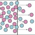
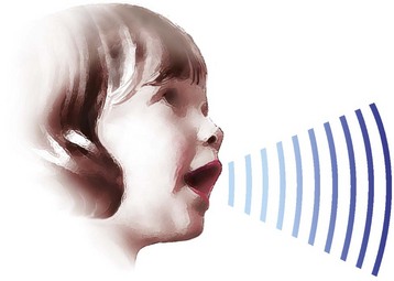
Sound is a form of mechanical energy that propagates through a medium as a wave of alternating pressure, causing local regions of compression and rarefaction (Fig. 42-1). The frequency (f ) of sound is the number of cycles of oscillation per second made by the sound source and the particles in the medium through which it moves. It is expressed in hertz (Hz, cycles per second). Sound waves propagate symmetrically away from the source at a constant velocity (v), which is the speed of sound in the medium. Distance between the wavefronts is the wavelength (λ) of the sound. The speed of sound through a medium can thus be represented as:

Amplitude is the strength of a sound wave, and the unit used to describe it is decibels (dB). The velocity of transmission of sound through a medium depends on its acoustic impedance and is determined by factors such as the stiffness, elasticity, and density of the medium. This accounts for the varying velocity of sound transmission through different tissues in the human body (Table 42-1). The average velocity of sound transmission through biologic tissue is 1540 m/sec. If the time taken by the US signal to return to the transducer is known, the distance of the target from the transducer (depth) can be computed.
| Tissue | Propagation Velocity of Sound (m/sec)* |
|---|---|
| Bone | 4080 |
| Muscle | 1580 |
| Blood | 1570 |
| Kidney | 1560 |
| Liver | 1550 |
| Soft tissue (average) | 1540 |
| Water | 1480 |
| Fat | 1450 |
| Lung | 600 |
| Air | 330 |
m/sec, Meters per second.
*Medical ultrasound device measurements are based on an assumed average propagation velocity of 1540 m/sec.
The emitted US signal travels through the tissue medium, and when it encounters a tissue interface it is reflected back. The degree of reflection of US from tissues is related to the changes in acoustic impedance (Z) between two tissue interfaces. The reflected echoes are detected by the transducer and converted into electrical energy; they are then processed by the US machine according to their strength and displayed as dots on the monitor. The brightness of each dot corresponds to the strength of the echo signal. Strong echoes produce bright white dots, weak echoes produce gray dots, and anatomic structures that do not reflect US appear as black dots. The position of the dot on the monitor represents the depth from which the echo is received. When all of these dots are combined, they produce a complete image of the area scanned.24–26
Modes of Ultrasound
A-Mode (Amplitude)
In amplitude, or A-mode, the echoes from tissue interfaces are represented on the monitor as a spike, and the spike height represents the amplitude of the echo.27 The distance of the interface from the transducer is calculated from the time taken for the signal to be sent and received, the “round-trip time.” A-mode US imaging is rarely used and is considered obsolete.
B-Mode (Brightness or Two-Dimension Mode)
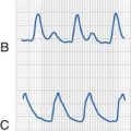
Brightness, or B-mode, is the most commonly used US mode. In this mode, the spike is converted to a dot and the brightness of the dot represents the amplitude of the returning signal.24–26 The position of the dot on the display represents the depth from which the signal is returning and depends on the round-trip time of the US signal. Multiple scan lines across a plane are combined to produce a single two-dimensional (2D) image. A series of frames are then displayed in rapid succession to give the impression of constant motion, the quality of which depends on the number of images displayed per second, that is, the frame rate.
M-Mode (Motion)
Motion, or M-mode, US is directed along a single scan line (sample line), and reflected signals along this scan line are converted to a brightness scale and displayed against a time axis. Because M-mode is produced from US signals along a single scan line, the 2D anatomy of the underlying body tissues should be studied first using the 2D mode (see later). M-mode is of particular interest when time resolution is necessary, such as when examining a target with rapid movement (e.g., the mitral valve during echocardiography).28
Doppler Ultrasound
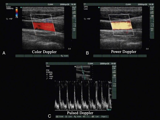
Doppler US (based on the Doppler principle) detects a shift in frequency between the emitted US waves and their echoes.29–32 It is used to detect and measure blood flow, and the major reflector for this purpose is red blood cells. Several modes are available:
 Color Doppler measures and color codes the direction and magnitude of the mean Doppler frequency shifts that occur in moving red blood cell and superimposes a color depiction of these data on the gray-scale image (Fig. 42-2, A).
 Power color Doppler depicts the amplitude, or power, of the Doppler signals (see Fig. 42-2, B). This allows better sensitivity for visualization of small vessels, but at the expense of directional information.
 Pulsed Doppler allows a sampling volume (or gate) to be positioned in a vessel visualized on the gray-scale image and displays a spectrum of the full range of blood velocities within the gate plotted as a function of time (see Fig. 42-2, C ).
The Ultrasound Machine
US machines are either cart-based or portable systems. Irrespective of their shape or size, US machines are made up of the following components: a monitor (where the clinical images are displayed), the US unit (where the signals are processed), the control panel (with the knobs and controls), one or more transducers, and a data storage device.33–35 For an anesthesiologist, the first encounter with an US machine can be quite intimidating. The wide array of knobs and controls that are available may be confusing. However, several controls are common in most US machines, and a clear understanding of their function (“knobology” ) is essential for optimal imaging.
Gain
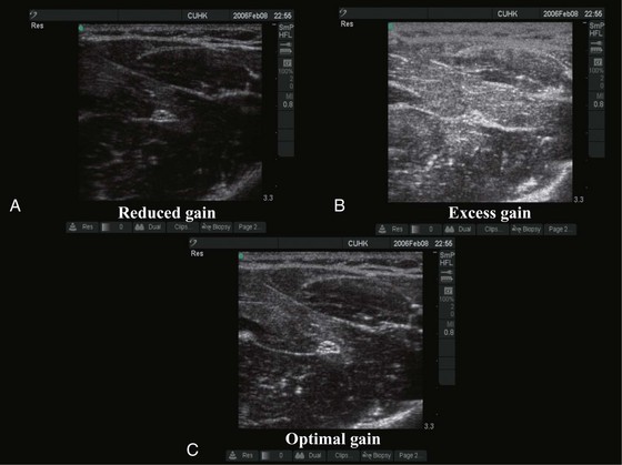
The gain control adjusts the amplification of the returning acoustic signals and is used to optimize the US image (Fig. 42-3). Reduced gain produces a dark image (see Fig. 42-3, A) and detail is masked. In contrast, too much gain produces a white image and detail is saturated (see Fig. 42-3, B). In some US machines there are separate controls for overall gain and gain for the near and far fields. “Auto-gain,” by which the US machine automatically adjusts the gain, is also available in some machines.
Ultrasound Transducers
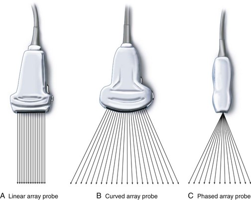
The transducer functions both as a transmitter and a receiver of the ultrasound signal.33–35 Three types of transducers are currently used (Fig. 42-4): (1) in a linear-array transducer, the piezoelectric crystals are arranged in a linear fashion and sequentially fired to produce parallel beams of ultrasound in sequence, creating a field of view that is rectangular and as wide as the footprint of the transducer (see Fig. 42-4, A); (2) a curved linear-array transducer has a curved surface, creating a field of view that is wider than the footprint of the probe (see Fig. 42-4, B), but at the cost of reduced lateral resolution in the far field as the scan lines diverge; (3) a phased-array transducer has a small footprint, but the ultrasound beam is steered electronically to produce a sufficiently wide far field of view. The ultrasound beam diverges from virtually the same point in the transducer (see Fig. 42-4, C ). Phased-array transducers are routinely used for transthoracic echocardiography.34 The footprints of these transducers are small enough to fit between the ribs and still produce a wide far field of view to image the heart. US transducers serve either a single frequency or a range of frequencies (broadband). For example, a transducer with the notation HFL38/13-6 indicates that it is a high-frequency broadband (13-6 MHz) linear transducer with a 38-mm footprint. Note that the nomenclature used for transducers varies among manufacturers of US devices.
Essentials of Musculoskeletal Ultrasound Imaging
Axis of Scan
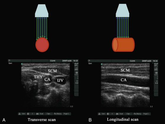
In diagnostic ultrasonography, scans are performed in the transverse, longitudinal (sagittal), oblique, or coronal axis. During a transverse (axial) scan the transducer is oriented at right angles to the target, producing a cross-sectional display of the structures (Fig. 42-5, A). During a longitudinal scan, the transducer is oriented parallel to and along the long axis of the target (e.g., a blood vessel or nerve) (see Fig. 42-5, B). During USGRA procedures, US scans are most commonly performed in the transverse axis. In this axis, the nerves, the adjoining structures, and the circumferential spread of the local anesthetic are easily visualized.
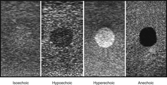
Echogenicity
Certain terms are frequently used to describe the sonographic appearance of musculoskeletal structures (Fig. 42-6):
Echogenic: A bright white structure against a dark background
Reflective: Synonymous with an echogenic structure
Isoechoic: A shade of gray that is of the same brightness or echogenicity as the surrounding tissues
Hyperechoic: A shade of gray that is bright white or brighter than the surrounding tissues
Hypoechoic: A shade of gray that is dark or less bright than the surrounding tissues
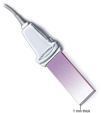
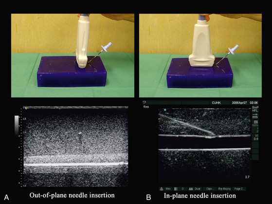
Axis of Intervention
The plane of US imaging is only 1 mm thick (Fig. 42-7); for a needle to be visible during US imaging it must lie within this narrow plane of imaging. During USGRA procedures, the block needle is inserted either outside of the plane (out-of-plane approach) (Fig. 42-8, A) or within the plane of the US beam (in-plane approach) (see Fig. 42-8, B). In the out-of-plane approach, the needle is inserted in the short axis and is initially outside the plane of imaging and therefore not visible. It becomes visible only when the needle crosses the plane of imaging and is seen as an echogenic dot on the monitor (see Fig. 42-8, A). It is important to note that this echogenic dot may be just the cross-sectional image of the shaft of the needle as it passes through the plane of the US beam and thus may not represent the tip of the needle. In the in-plane approach, the needle is inserted along the long axis of the transducer in the plane of imaging and therefore both the shaft and tip of the needle are visible on the monitor.
Both approaches are commonly used, and no data have shown that one is better than the other. Proponents of the out-of-plane approach13,14,36 have had great success with this method and claim that it causes less needle-related trauma and pain because the needle is advanced through a shorter distance to the target. However, critics of the short-axis approach express concerns that the inability to reliably visualize the needle and to use tissue movement as a surrogate marker to locate the needle tip during a procedure can lead to complications. The needle is better visualized in the in-plane approach,37,38 but this requires good hand and eye coordination and reverberation artifacts from the shaft of the needle can be problematic. Moreover, there are claims that the in-plane approach also causes more discomfort in awake patients because longer needle insertion paths are required.13,14,36
Needle Visibility
The ability to visualize the needle during a US-guided procedure is critical for precision, safety, and success. However, this is often limited by the dispersion of the reflected US signals away from the transducer. Several factors have been identified that can influence needle visibility. The shaft of the needle is better visualized in the long axis than in the short axis, and its visibility decreases linearly with steep angles of insertion and smaller needle diameters. The needle tip is better visualized when it is inserted in the long axis for shallow angle of insertion (less than 30 degrees) and in the short axis when the angle of insertion is steep (greater than 60 degrees). This is also true when the needle is inserted with its bevel facing the US transducer. To overcome the effect of angle on needle visibility, some high-end US machines allow the operator to steer the US beam toward the needle during steep needle insertions. However, this requires experience and decreases in needle visibility can still occur. Needle visibility is also enhanced in the presence of a medium-sized guidewire. Priming a needle with saline or air, insulating it, or inserting a stylet before insertion does not improve visibility.39–41
We think that the anesthesiologist’s skill in aligning the needle along the plane of imaging is by far the most important variable influencing needle visibility because minor deviations of even a few millimeters from this plane will result in inability to visualize the needle. Even with experience, needle tip visibility is a problem when performing blocks at a depth in areas that are rich in fatty tissue. Under such circumstances, gently jiggling (rapid in-and-out movement) the needle and observing tissue movement or performing a test injection of saline or 5% dextrose (1 to 2 mL) and observing tissue distention can help locate the position of the needle tip. Five percent dextrose is preferred for the latter when nerve stimulation is used because it does not increase the electric current required to elicit a motor response.42
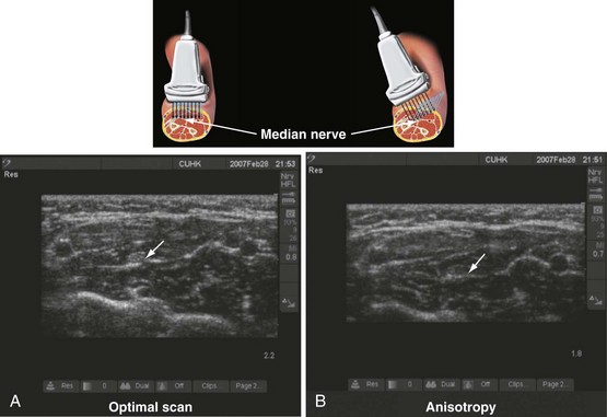
Anisotropy
Anisotropy, or angular dependence, is a term used to describe the change in echogenicity of a structure with a change in the angle of insonation of the incident US beam (Fig. 42-9).43 It is frequently observed during scanning of nerves, muscles, and tendons. This occurs because the amplitude of the echoes returning to the transducer varies with the angle of insonation. Nerves are best visualized when the incident beam is at right angles (see Fig. 42-9, A); small changes in the angle away from the perpendicular can significantly reduce their echogenicity (see Fig. 42-9, B). Therefore, during USGRA procedures, the transducer should be tilted, from side to side, to minimize anisotropy and optimize visualization of the nerve.44 Although poorly understood, different nerves also exhibit differences in anisotropy, which may be related to the internal architecture of the nerve.
Identification of Nerves, Tendons, Muscle, Fat, Bone, Fascia, Blood Vessels, and Pleura
Nerves
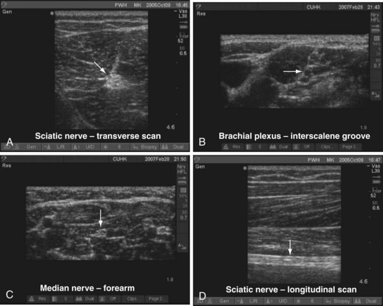
On a transverse scan, nerves appear round, oval, triangular, lip shaped, or even flat.45,46 Nerves also assume different shapes along their course depending on the surrounding structures. The echogenicity of nerves also varies and depends on the nerve and area scanned. They are generally hyperechoic and stand out in the background of the hypoechoic muscles (Fig. 42-10, A), but they can also appear hypoechoic with a hyperechoic rim (see Fig. 42-10, B). They also have been described to have a fascicular or honeycomb appearance (i.e., echogenic structures with internal punctate, echo-poor spaces) (see Fig. 42-10, C ). On longitudinal scan, the appearance of peripheral nerves has been likened to a “tram track”; that is, parallel hyperechoic lines are seen against a background of echo-poor space (see Fig. 42-10, D). Nerve motion also can be demonstrated on dynamic US imaging.
Tendons
Tendons appear to have numerous fine parallel hyperechoic lines separated by fine hypoechoic lines (fibrillar pattern) on long-axis scans.46 Compared with nerves, tendons have more hyperechoic lines and move more than adjacent nerves when the corresponding muscle is contracted or passively stretched.
Muscle
Muscle fibers are hypoechoic, but the connective tissue structure enveloping the entire muscle (epimysium) is hyperechoic.47,48 The perimysium that envelops individual muscle fascicles is also hyperechoic. Muscle fibers converge to become tendons or aponeurosis.
Bone
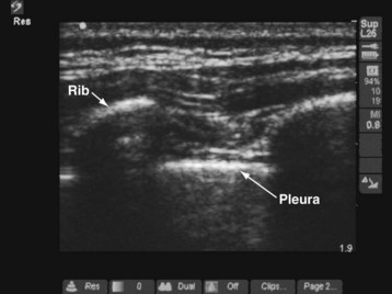
Bone reflects most of the US energy. Therefore it appears bright and has a hyperechoic edge on US imaging, with a large anechoic shadow (acoustic shadow) distal to it (Fig. 42-11).
Blood Vessels
Arteries are identified by their intrinsic pulsatility, are not compressible, and have anechoic lumens. Veins are not pulsatile, are compressible, and have anechoic lumens. Color Doppler or power Doppler modes can also be used to demonstrate blood flow and differentiate arteries from veins (see Fig. 42-2).
Pleura
The pleura appear as a hyperechoic line on US imaging (see Fig. 42-11).49–51 During scanning of the intercostal space, the pleural line is located slightly below the hyperechoic ribs. “Comet-tail” artifacts may be present as a series of vertical lines arising from the pleura. On real-time imaging, lung sliding movement between the parietal and visceral pleura can be discerned from movement of the comet-tail artifacts (“lung sliding sign”).
Special Techniques
Tissue Harmonic Imaging
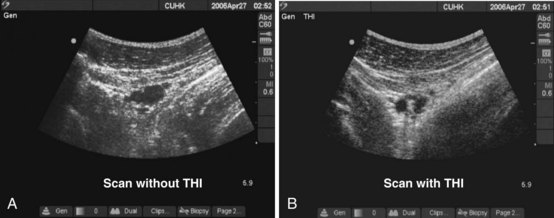
The term harmonic refers to frequencies that are integral multiples of the frequency of the transmitted pulse (which is also called the fundamental frequency or first harmonic). The second harmonic has a frequency of twice the fundamental frequency. Harmonics are generated in the tissues by the nonlinear propagation of sound. Tissue harmonic imaging (THI) is a technique in which the harmonic signals reflected from tissue interfaces are selectively displayed.52–54 This results in reduced image artifacts, haze, and clutter and improved contrast resolution (Fig. 42-12).
Compound Imaging
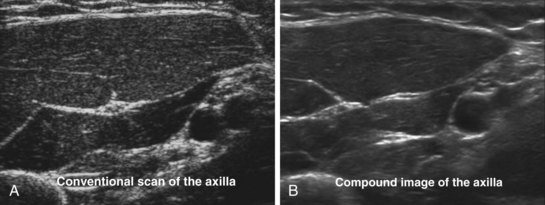
US imaging depends on the reflection of the US from tissue interfaces. Not all tissues are good reflectors, and certain structures also cause scattering of the US signals. Unlike reflected signals, scattered signals radiate in all directions. As a result, only a small amount of energy is reflected back to the transducer. The scattering of the US signal results in speckle artifacts, also described as noise, which reduces image resolution and makes the US image appear grainy. Compound imaging is a technique used to improve resolution by reducing the contrast-to-noise ratio (speckle).55 The US beam from the transducer is electronically steered, and the same structure is imaged from several different angles. The returning echoes are then processed with simultaneous filtering of the artifacts in real time, producing a composite image that has reduced noise or speckle and improved definition (Fig. 42-13).
Panoramic Imaging
B-mode (2D) ultrasonography has a limited field of view and allows visualization of only a small portion of any large structure. Panoramic imaging, as the name implies, is a technique used to extend the field of view so that larger structures and their surrounding tissues can be visualized together.56 During a panoramic scan, the operator slowly slides the US transducer across an area of interest. During this motion, multiple images are acquired from many different transducer positions across the area of interest. The registered image data are accumulated in a large buffer and then combined to form the composite panoramic image (Fig. 42-14). Although useful for annotation, documentation, teaching, and research, it is rarely used in children during USGRA procedures.
Artifacts
US artifacts are structures that are visible in the US image that do not correlate with any anatomic structure.57 The US machine makes the following assumptions when generating an image:
1. The US beam is considered to travel only in a straight line, with a constant rate of attenuation.
2. The average speed of sound through body tissue is considered to be 1540 m/sec.
3. The US beam is assumed to be infinitely thin, with all echoes originating from its central axis.
4. The depth of a reflector is calculated by determining the round-trip time of the US signal.
Reverberation Artifact
Reverberation artifacts, also known as repetitive echoes, occur when repeated reflection of US occurs between two highly reflective surfaces.58 Some of the US signals returning to the transducer are reflected back, then strike the original interface, and are reflected back toward the transducer a second time. As a result, the first reverberation artifact is twice as far from the skin surface as the original interface. A second or third reverberation artifact also may be seen. Because of attenuation, the intensity of the artifacts decreases with increasing distance from the transducer. Reverberation artifacts are frequently seen during US-guided axillary brachial plexus block, particularly when the needle is inserted in the long axis.
Mirror Image Artifact
Mirror image artifact is a type of reverberation artifact that occurs at highly reflective interfaces.59 The first image is displayed in the correct position, and a false image is produced on the other side of the reflector because of its mirrorlike effect.
Propagation Speed Artifact
Propagation speed artifacts occur when the medium through which the US beam passes does not propagate at 1540 m/sec, resulting in echoes that appear at incorrect depths on the monitor. An example of propagation speed artifact is the “bayonet artifact,”60 which has been reported during an US-guided axillary brachial plexus block. The shaft of the needle appeared bent when it accidentally traversed the axillary artery. This happens because of the difference in the velocity of sound between whole blood (1580 m/sec) and soft tissue (1540 m/sec).
Scanning Routine
Being able to consistently produce high-quality images of the area scanned is vital for safety and success during any USGRA procedure. Without optimal images, it is not possible to accurately identify musculoskeletal structures or perform interventions with precision. We have found that following a “scanning routine” or a set of simple steps, which is repeatable, is essential for optimal imaging; the routine that we follow is outlined in Table 42-2. Although the suggested routine may appear complicated at first, with repetition these steps are gradually internalized. Attaching a card with the scanning routine to the US machine facilitates easy recall.
1. Turn on the ultrasound machine.
3. Select an appropriate transducer.
4. Dim the lights in the room.
5. Assume a comfortable position.
6. Apply liberal amount of ultrasound gel.
8. Orient the transducer and image.
9. Select the appropriate ultrasound settings (preset, frequency—for broadband transducers, depth, gain, and focus point).
10. Mark the position of the transducer on the patient’s skin once an optimal image is obtained before the intervention.
Scout Scan
The aim of the scout scan, or the preintervention scan, as the name implies, is to examine the area of interest before the intervention. This has also been referred to as a “mapping scan.” During the scout scan, steps 8 and 9 described in Table 42-2 are performed, the sonoanatomy of the area is visualized, and the image is optimized. Once an optimal view with the target structure is obtained and the best possible site for needle insertion is determined, it is advisable to mark the position44 of the transducer on the patient’s skin so the transducer can be returned to the same position after sterile preparations have been completed. It is common to diagnose anatomic variations during the scout scan. The operator can then decide whether to continue with the block in the same location or to choose an alternative approach or technique that may be safer. This assessment of anatomic variation is one of the major benefits of using US for regional anesthesia.
General Considerations in Children
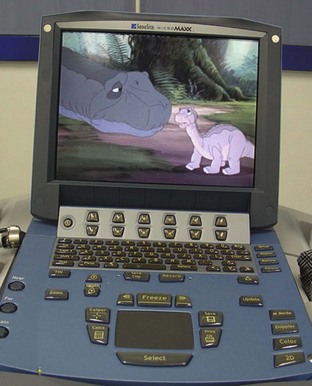
Preparations for an ultrasound-guided nerve block should begin during the preoperative visit by adequately explaining the technique, its benefits and risks, and, more importantly, the possibility of a failed block to the parents. In the event of failure, a contingency plan to quickly convert to general anesthesia or another form of postoperative analgesia must always be in place. In children, most regional anesthetic procedures are performed while the child is anesthetized. However, in a cooperative child or under special circumstances, such as in a child with difficult airway or a child predisposed to malignant hyperthermia, it is possible to perform the block after light sedation. We find that it is easy to explain the procedure to children who are older than 8 years of age. Some of them may even express a wish to stay awake and observe the US images during the block. Eutectic mixture of local anesthetic (EMLA) cream applied an hour before the procedure to the skin over the area where the block needle and the intravenous catheter are to be inserted helps reduce needle-related pain. Parental presence during the nerve block may also be helpful. In older children, allowing the child to listen to favorite music through a personal stereo or watch a video are useful distraction techniques that make the whole experience a more pleasant one for the child. We have connected a DVD player to our US machine, and this is used to play movies or cartoons through the monitor during the surgical procedure (E-Fig 42-1).

Tips and Tricks for Success
Certain steps are common to all US-guided procedures, and, if followed, they may increase success. The lights in the room must be dimmed to avoid any glare or reflection from the US monitor. The operator must assume a comfortable position (Fig. 42-15). For upper extremity blocks, the operator sits at the ipsilateral head end of the child and the US machine is placed directly in front. For lower extremity blocks, such as femoral nerve block, the operator stands on the ipsilateral side of the child and the US machine is placed on the opposite side. For lower extremity or central neuraxial blocks in the lateral position, the operator sits behind the child and the US machine is placed in front, with the monitor in the line of view of the operator. Because of the small muscle bulk in young children the nerves are relatively superficial and can most frequently be easily visualized using high-frequency linear transducers. The exact choice of transducer depends on the area scanned, but a high-frequency linear transducer with a small footprint (13-6 MHz, 25-mm footprint) is particularly suited for young children. The 15-6–MHz broadband linear-array transducer, which has recently become available, is also useful for most blocks in young children. In older children, a 10-7–MHz broadband linear-array transducer, which allows greater flexibility with the depth of scan, is adequate for most procedures. Low-frequency (5-2 MHz) curved-array transducers are rarely used in children but are useful for imaging deeper structures such as the lumbar plexus and sciatic nerve in older children.
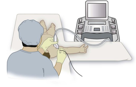
To improve dexterity, hold the transducer with the nondominant hand and perform interventions with the dominant hand. Holding the transducer steady for even short periods can be quite testing. We have found that gently resting the hand that is holding the transducer on the child during a procedure helps to keep the transducer steady (see Fig. 42-15). It is important to maintain light contact between the transducer and the skin because excessive pressure in a child will cause the veins to collapse or distort the anatomy of the area of interest. Always apply liberal amounts of US gel to maintain adequate acoustic coupling between the skin and the transducer because even small amounts of air trapped between the two can result in artifacts. We use sterile US gel from single-use sachets for all US-guided peripheral nerve blocks. At any given time during an US-guided intervention either the transducer or the needle must be moved. It is impossible to maintain the needle within the plane of imaging if both are moving, a common error by novices. This results in an inability to visualize the needle. If the needle is not visible in the US image, a good strategy is to keep the needle steady and manipulate the transducer (slide, tilt, or rotate) until the needle becomes visible on the monitor. Thereafter the transducer should be held steady and the needle should be gently advanced to the target nerve, maintaining it in the imaging plane. When the angle of insertion of the needle is steep (greater than 60 degrees), it is preferable to introduce the needle in the short axis using the out-of-plane technique. However, if the in-plane approach is used for all US-guided interventions, as in our case, inserting the needle a few centimeters away from the edge of the transducer may improve needle visibility by decreasing the angle between the needle and the imaging plane.
Injecting air into the area of the intervention must be avoided at all cost because air bubbles in the field of imaging will degrade the US image. We routinely introduce the needle into the subcutaneous tissue and then purge it with saline or the local anesthetic to remove any air from the shaft of the needle, extension, and syringe system before proceeding with the block. An assistant aids with the injection. When the needle tip is close to the target nerve, the assistant gently aspirates to exclude unintended intravascular placement. The assistant must avoid generating excessive negative pressure because small blood vessels are prone to collapse. A short length of extension tubing attached between the needle and the local anesthetic syringe allows the operator to hold the needle steady while the assistant performs the injection.61 We routinely perform a test injection with 1 to 2 mL of saline or 5% dextrose (when nerve stimulation is also used) and visualize the distribution of the injectate in real time before injecting the local anesthetic. Failure to visualize the injectate in the US image indicates that the needle is not in the plane of imaging or it is intravascular until proven otherwise. No further injection should be made until the needle is repositioned and the distribution of the injectate is confirmed.
Specific Ultrasound-Guided Nerve Blocks
Upper Extremity Blocks
Supraclavicular Brachial Plexus Block
Supraclavicular brachial plexus block has been described in children, although it is rarely used because of fear of pleural puncture and pneumothorax.62 US-guided supraclavicular brachial plexus block has recently been successfully performed in a series of 17 children aged younger than 6 years for orthopedic upper limb surgeries.63 Even though the brachial plexus and cervical pleura are clearly delineated using US in the supraclavicular fossa, this technique should be performed only by experienced operators because of the close proximity between the cervical pleura and the brachial plexus.
The child’s head rests on a head ring and is slightly turned to the contralateral side, and a small roll is placed between the scapula. For a right-sided block, a right-handed operator stands or sits at the head end of the child and the US machine is placed directly in front on the ipsilateral side (see Fig. 42-15). The position of the operator and US machine is reversed for a left-sided block. In the supraclavicular fossa, the subclavian artery lies on top of the first rib. The trunks and divisions of the brachial plexus are superficial and lateral to the subclavian artery and sandwiched between the scalenus anterior and scalenus medius muscle (Fig. 42-16). A linear-array transducer (13-10 MHz) is used to perform the block; the hockey stick probe or a linear-array transducer with a small footprint (25 mm) is particularly suited for this block.
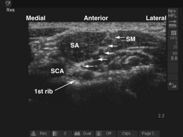
During the scout scan the transducer is positioned parallel to and against the clavicle and the subclavian artery is identified. The trunks and divisions of the brachial plexus often look like a bunch of grapes on the superficial and lateral aspect of the subclavian artery (see Fig. 42-16). The cervical pleura and lung are deep to the first rib. The operator should bear in mind that the acoustic shadow of the first rib can obscure the view of the pleura and lung (see also Fig. 41-21 and Chapter 41 for the landmark-guided techniques). The block needle is inserted in the long axis (in-plane) of the transducer in a lateral to medial direction, keeping the pleura in view. A test injection with saline is performed to ensure optimal needle position, after which the calculated dose of local anesthetic is injected in aliquots.
Infraclavicular Brachial Plexus Block
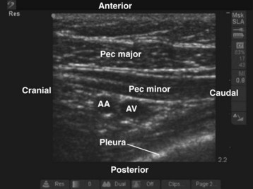
During the scout scan the second part of the axillary artery and the axillary vein are identified deep to the pectoral muscles (Fig. 42-17). The axillary artery is located superior to the vein, and the cords of the brachial plexus are closely related to the axillary artery at this level. The medial cord is situated caudal to the axillary artery, often between the axillary artery and vein, whereas the posterior and lateral cords are posterior and cephalad to the artery, respectively (see Fig. 42-17). Despite this relation, in most cases it is not easy to identify all three cords of the brachial plexus in a single plane of imaging. If the transducer is moved medially, the pleura usually comes into view (Fig. 42-18). In infants and young children, the margin of safety between the cords of the brachial plexus and the pleura is relatively small and pleural puncture is a risk if the block is performed in this medial position. Therefore we recommend that the infraclavicular brachial plexus block be performed laterally where the pleura is not visible in the US image.
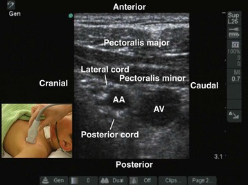
FIGURE 42-17 Sagittal sonogram of the left infraclavicular fossa. AA, Axillary artery; AV, axillary vein.
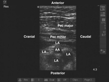
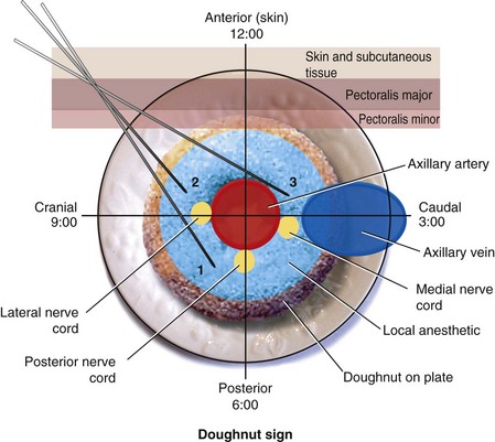
We prefer to perform multiple injections targeting the areas where the three cords of the brachial plexus are located. The aim is to produce a circumferential spread of the local anesthetic around the axillary artery, the “doughnut sign” (Fig. 42-19), which correlates well with successful brachial plexus anesthesia.64–71 This perivascular injection technique is best visualized by imagining the transverse image of the axillary artery as a clock face with its 12-o’clock position in its anterior aspect and the 6-o’clock position in the posterior aspect of the artery (Fig. 42-20). The block needle is inserted using in-plane technique from a cranial to caudal direction (see Fig. 42-20), and one third of the total dose of local anesthetic is injected close to each of the posterior (6-o’clock position), lateral (9-o’clock position), and medial (3-o’clock position) cords.38 Because the angle of needle insertion is fairly steep with this approach, the needle is rarely seen on the US image and the operator has to gently jiggle the needle to locate the needle tip. A subtle pop may be felt as the needle tip traverses the epimysium of the pectoralis minor muscle. A test injection with 1 to 2 mL of saline should be performed before the local anesthetic injection to ensure optimal needle position and distribution of the injectate (see also Fig. 41-20 and Chapter 41 for landmark-guided techniques).
Axillary Brachial Plexus Block
US-guided axillary brachial plexus block is typically performed with the child in the supine position.72–74 The arm is abducted (to 90 degrees) and externally rotated so that the palm of the hand is facing the ceiling. The operator sits at the ipsilateral head end of the child, and the US machine is positioned directly in front (see Fig. 42-15). Because the nerves of the brachial plexus are relatively superficial in the axilla a high-frequency linear-array transducer (13-6 MHz) is used. During the scout scan, the transducer is positioned just below the lateral border of the pectoralis major muscle, with its orientation marker directed laterally (Fig. 42-21). The resultant image in the monitor is a transverse scan of the axillary structures. The pulsatile vessel in the image is the axillary artery. The axillary vein is located medial to the artery. It is common to see more than one vein in the scan (see Fig. 42-21).
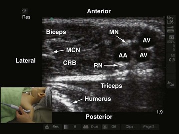
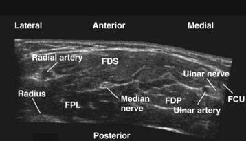
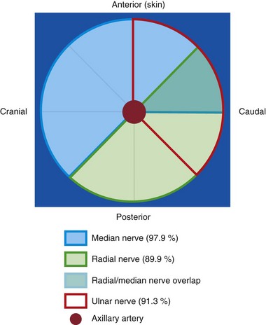
At this level, the three major nerves of the brachial plexus (the median, ulnar, and radial nerves) lie very close to the axillary artery. In adults, when the arm is abducted and externally rotated, the median nerve is located on the anterior or anterolateral side of the axillary artery (97.9%), the ulnar nerve is located on the anteromedial side of the artery (91.3%), and the radial nerve is located posterior to the axillary artery (89.9%) (Fig. 42-22).75 No comparable data exist in children, but we find that the location of the median, ulnar, and radial nerves in children closely reflect those in adults. To accurately identify these three nerves it may be necessary to trace the nerve distally along its course. The musculocutaneous nerve is frequently seen between the coracobrachialis and the biceps muscle or within the substance of the coracobrachialis muscle (see Fig. 42-21).76,77 Occasionally, the musculocutaneous nerve also may be located very close to the median nerve, and local anesthetic injected close to the median nerve may affect the musculocutaneous nerve. The shape of the musculocutaneous nerve varies along its course, and it may appear oval, round, elliptical, or even triangular.
We prefer the in-plane approach for needle insertion during axillary brachial plexus block in both sedated and anesthetized children. The block needle is inserted from the lateral to the medial side of the arm, keeping it within the plane of the US imaging. A subtle pop is often felt when the tip of the needle traverses the epimysium of the biceps muscle and enters the fascial plane containing the neurovascular bundle. Multiple injections are required to block the median, radial, and ulnar nerves. The objective is to produce a circumferential spread of local anesthetic around the artery (i.e., “the doughnut sign” in the US image). To achieve this, local anesthetic is injected close to the anterior (12-o’clock position), posterior (6-o’clock position), and lateral (9-o’clock position) aspects of the axillary artery. The musculocutaneous nerve is then identified and selectively blocked using a few milliliters of local anesthetic.77 We have found this approach to be technically simple, safe, and effective in producing brachial plexus blockade in children (see also Fig. 41-19 and Chapter 41 for landmark-guided techniques).
Selective Peripheral Nerve Blocks of the Upper Extremity
Selective blockade of the nerves of the upper extremity is very rarely performed in children. It can be used to rescue incomplete or partial axillary brachial plexus block or provide analgesia or anesthesia over a specific dermatome.78 We have also found it to be useful for US-guided differential nerve blockade in adults undergoing ambulatory hand surgery, and the same also may be applicable in children. In this technique an axillay brachial plexus block is performed using a short-acting local anesthetic agent such as lidocaine and combined with a peripheral nerve block (e.g., a median or ulnar nerve block, depending on the dermatomes involved) in the forearm using a long-acting drug (bupivacaine or ropivacaine). Because of the shorter duration of action of lidocaine compared with bupivacaine or ropivacaine, the child regains protective motor function of the elbow fairly quickly after surgery (2 to 4 hours) while still enjoying prolonged postoperative analgesia from distal nerve blockade. All of the major nerves of the upper extremity (median, ulnar, and radial) can be identified using high-frequency linear-array transducers (13-10 MHz), and it is possible to selectively block these nerves at various sites along their course with only 1 to 2 mL of local anesthetic. We prefer the in-plane needle insertion technique and use a short-beveled block needle for this purpose.
Median Nerve
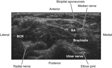
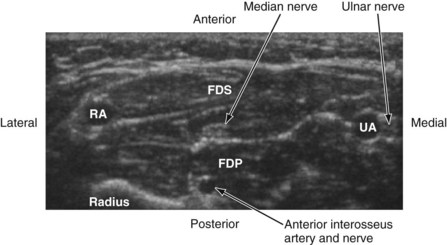
The median nerve is closely related to the brachial artery throughout its course in the arm. In the upper part, it is lateral to the artery; in the middle of the arm it crosses the artery from the lateral to medial side and continues on the medial side all the way up to the elbow. In the antecubital fossa, the median nerve lies medial to the brachial artery, behind the bicipital aponeurosis, and in front of the brachialis muscle (Fig. 42-23). In the forearm, the median nerve is deep to the flexor digitorum superficialis and on the surface of the flexor digitorum profundus (Fig. 42-24) and accompanied by the median artery that is a branch of the anterior interosseous artery. Pulsations of the latter can occasionally be observed on the US image. A few centimeters proximal to the wrist, the median nerve becomes superficial and lies between the tendon of the flexor carpi radialis (laterally) and the flexor digitorum superficialis (medially) and may also be overlapped by the tendon of the palmaris longus. Because the nerve is superficial at this level and it can be difficult to differentiate the nerve from the tendons, we prefer to perform median nerve block at the midforearm, where it is clearly delineated (see also Fig. 41-22 and Chapter 41 for landmark-guided techniques).
Ulnar Nerve
In the arm, the ulnar nerve runs on the medial side of the brachial artery up to about the midhumeral level or the insertion of the coracobrachialis muscle, where it pierces the medial intermuscular septum and enters the posterior compartment of the arm. At the elbow, it passes behind the medial epicondyle to enter the ulnar nerve sulcus. Although the nerve is palpable and superficial at the sulcus, it is often difficult to visualize using US because of bony and contact artifacts. The ulnar nerve then enters the proximal forearm and runs between the flexor digitorum profundus (posterior) and the flexor digitorum superficialis (laterally) muscles, and in the distal forearm it is accompanied by the ulnar artery (lateral) (see Fig. 42-24). Close to the wrist, the ulnar nerve is lateral to the flexor carpi ulnaris muscle. The ulnar artery may be used as a reference to locate the ulnar nerve. Once the artery is located, the nerve is traced backward and the local anesthetic injection is performed away from the artery (see Chapter 41 for landmark-guided techniques).79
Radial Nerve
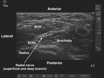
In the arm the radial nerve is posterior to the brachial artery. It then leaves the artery to enter the radial (spiral) groove on the back of the arm, where it is accompanied by the profunda brachii artery. In the distal arm the radial nerve pierces the lateral intermuscular septum and enters the anterior compartment. In the antecubital fossa it is lateral to the biceps tendon and lies in an intermuscular gap between the brachialis (medially), the brachioradialis, and the extensor carpi radialis longus (laterally) (Fig. 42-25). At the level of the lateral epicondyle the radial nerve gives off the posterior interosseous nerve (deep branch of the radial nerve), which leaves the fossa by piercing the supinator muscle. In the forearm, the radial nerve (superficial branch of the radial nerve) continues as a pure cutaneous nerve and supplies the radial half of the dorsum of the hand and the proximal parts of the dorsal surfaces of the thumb and index finger. The radial nerve is best blocked before its division in the antecubital fossa (see also Figs. 41-2, 41-23, and Chapter 41 for landmark-guided techniques).78
Lower Extremity Blocks
Lumbar Plexus Block
The lumbar plexus results from the union of the ventral rami of the first four lumbar spinal nerves within the substance of the psoas major muscle80 The plexus may also receive contributions from the 12th thoracic nerve or the 5th lumbar nerve. In adults, the plexus is located between the fleshy anterior part of the psoas major muscle, which arises from the anterolateral part of the vertebral bodies and the intervertebral disc, and the accessory posterior part of the muscle that originates from the anterior surface of the transverse process.81 Local anesthetic injected into this intramuscular plane, also referred to as the psoas compartment, produces ipsilateral lumbar plexus block.
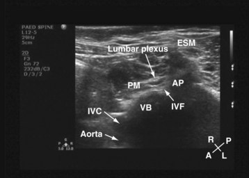
For a transverse scan,82 the US transducer is positioned approximately 2 to 3 cm lateral to the lumbar spine at the L3-4 vertebral level, with its orientation marker directed laterally. We also prefer to align the transducer slightly medially so as to produce a paramedian oblique transverse scan (PMOTS) of the lumbar paravertebral region. Also during a PMOTS of the lumbar paravertebral region, the US beam can be insonated either at the level of the transverse process (PMOTS-TP, Fig. 42-26) or through the gap between the two adjacent transverse process (i.e., the intertransverse space [ITS]) producing a PMOTS-ITS scan (Fig. 42-27). In a typical PMOTS-ITS sonogram of the lumbar paravertebral region, the erector spinae muscle, the vertebral body, the psoas major muscle, quadratus lumborum muscle, and the anterolateral surface of the vertebral body are clearly visualized (see Fig. 42-27). The inferior vena cava (on the right side) and the aorta (on the left side) are also identified anterior to the vertebral body. The lower pole of the kidney is closely related to the anterior surfaces of the quadratus lumborum and psoas muscle and is seen as an oval structure that moves with respiration in the retroperitoneal space. The lumbar plexus is not sonographically visualized in all patients, but when it is visualized, it appears as an oval hyperechoic structure in the posterior part of the psoas muscle (see Fig. 42-27) and close to the intervertebral foramen. In contrast, because the acoustic shadow of the transverse process obscures the posterior part of the psoas muscle and the area close to the intervertebral foramen during a PMOTS-TP, the lumbar plexus is rarely visualized in this US scan window (see Fig. 42-26). Therefore, if a transverse scan is performed during an ultrasound-guided lumbar plexus block, it is our recommendation to use the PMOTS-ITS.
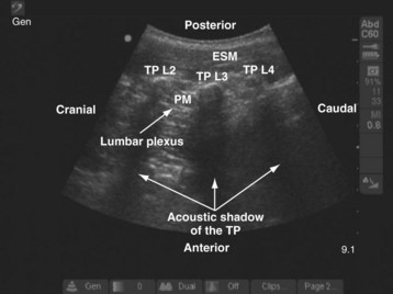
For a sagittal scan of the lumbar paravertebral region, the US transducer is positioned approximately 2 to 3 cm lateral and parallel to the lumbar spine,83 with its orientation marker directed cranially. In a typical sagittal sonogram of the lumbar paravertebral region, the L2, L3, and L4 transverse processes with their acoustic shadow produce what we refer to as the “trident sign” (Fig. 42-28) because of its similarity to the trident (Limia tridens or tridentis) that is often associated with Poseidon (the god of the sea in Greek mythology) and the trishula of the Hindu god Shiva. The hypoechoic psoas muscle is seen between the transverse processes, and the lumbar plexus is identified as hyperechoic longitudinal striations within the posterior aspect of the muscle. A laterally positioned transducer will produce a suboptimal scan without the trident, and the lower pole of the kidney, which can reach the L4-5 level in young children, will come into view.
Femoral Nerve Block
The femoral nerve is the largest branch of the lumbar plexus and is the major nerve of the anterior (extensor) compartment of the thigh. It is formed by the dorsal division of the anterior primary rami of spinal nerves L2, L3, and L4. It exits the pelvis and enters the femoral triangle in the thigh by passing under the inguinal ligament just lateral to the femoral artery. In the thigh it lies in the groove between the iliacus and the psoas major muscle, outside the femoral sheath, and lateral to the artery. A high-frequency (13-10 MHz) linear-array transducer is used to scan the femoral nerve.36,84 On a transverse sonogram the femoral nerve is seen as an oval or triangular hyperechoic structure lateral to the femoral artery (Fig. 42-29). The femoral nerve exhibits marked anisotropy, and it may be necessary to tilt or rotate the transducer during the scan before it can be visualized. In young children one must avoid exerting too much pressure during the scan because it is easy to collapse the femoral vein.
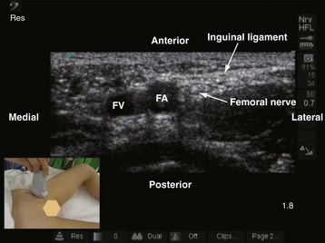
A femoral nerve block is used to provide postoperative analgesia after femoral fractures. It is performed with the child in the supine position. The ipsilateral lower limb is slightly abducted and externally rotated, and the knee is also slightly flexed. A right-handed operator stands on the right side of the child, and the US machine is positioned directly in front on the contralateral side. The sides of the operator and the US machine are reversed for a left-handed operator. The scout scan is performed with the transducer positioned parallel and just below the inguinal ligament. This ensures that the femoral nerve is scanned before its division. Once an optimal view of the femoral nerve is obtained, the block needle is inserted in the long axis (in-plane) of the US transducer from the lateral to medial side and directed to the lateral aspect of the femoral nerve. A test injection with saline (1 to 2 mL) is performed before the local anesthetic is injected to confirm that the needle is deep to the fascia iliaca and to observe the distribution of the injectate in relation to the femoral nerve (see also Fig. 41-32 and Chapter 41 for landmark-guided techniques).
Subsartorial Saphenous Nerve Block
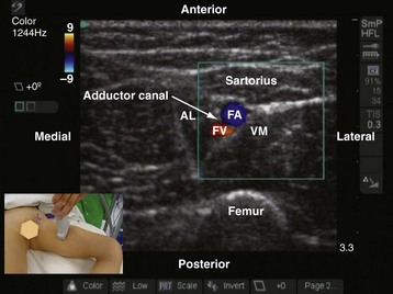
The saphenous nerve is a branch of the anterior division of the femoral nerve and supplies the skin on the medial aspect of the leg and foot up to the ball of the big toe. In the thigh, the saphenous nerve is located in the subsartorial canal and local anesthetic injected into this intramuscular space produces a saphenous nerve block.85–87 The subsartorial canal is also referred to as the adductor canal or Hunter’s canal and is situated on the medial side of the middle one third of the thigh and extends from the apex of the femoral triangle, above, to the tendinous opening in the adductor magnus muscle, below. The canal is triangular in cross section, and its anterior wall is formed by the vastus medialis muscle, the posterior wall or floor is formed by the adductor longus, and the medial wall or roof is formed by a strong fibrous membrane that is overlapped by the sartorius muscle (Fig. 42-30). The subsartorial canal contains the following structures: femoral artery and vein, saphenous nerve, nerve to vastus medialis, and the two divisions of the obturator nerve. The femoral vein lies posterior to the artery in the upper part and lateral to the artery in the lower part of the canal. The saphenous nerve crosses the femoral artery anteriorly from the lateral to the medial side in the canal.
Sciatic Nerve Block
The sciatic nerve is the largest mixed nerve in the body and arises from the lumbosacral plexus (L4, L5, S1-3). It innervates the posterior aspect of the thigh and the entire lower limb below the knee except for a small patch of skin on the medial aspect of the leg and ankle, which is innervated by the saphenous nerve. Sciatic nerve block is frequently used to provide analgesia for foot (clubfoot) and leg surgery in children. Several different approaches to the sciatic nerve have been described in the literature. Most approaches described to date rely on surface anatomic landmarks (anterior, transgluteal, infragluteal, lateral, posterior subgluteal, proximal thigh, or at the popliteal fossa). Recently, US-guided sciatic nerve block also has been described.88,89 A proximal approach to the sciatic nerve is selected when surgery involves the hip (rare in children) or block of the posterior cutaneous nerve of the thigh is warranted. Because sciatic nerve block is most frequently used for foot (clubfoot) surgery in children, a distal approach to the sciatic nerve at the popliteal fossa is usually preferred (see also Fig. 41-31 and Chapter 41 for landmark-guided techniques).
Sciatic Nerve Block at the Subgluteal Space
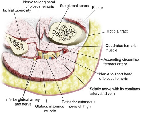
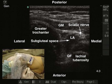
The sciatic nerve exits the pelvis through the greater sciatic foramen, between the piriformis and the superior gemelli muscles, and enters the subgluteal space below the piriformis muscle. It then descends over the dorsum of the ischium, lying on the dorsal surface of the gemellus superior muscle, tendon of obturator internus, gemellus inferior muscle, and quadratus femoris muscle (in a cranial to caudal relation) before it enters the hollow between the greater trochanter and the ischial tuberosity and then goes on to the posterior compartment of the thigh. The anterior surface of the gluteus maximus covers the upper part of the sciatic nerve; and immediately distal to its lower border (infragluteal position), the sciatic nerve is fairly superficial. In between the greater trochanter and the ischial tuberosity, the sciatic nerve lies in the subgluteal space, which is a well-defined anatomic space between the anterior surface of the gluteus maximus and the posterior surface of the quadratus femoris muscle (Fig. 42-31).88,89 Other structures that are present in the subgluteal space include the posterior cutaneous nerve of the thigh, inferior gluteal vessels and nerve, nerve to the short and long head of the biceps femoris, the comitans artery and vein of the sciatic nerve, and the ascending branch of the medial circumflex artery (see Fig. 42-31). Local anesthetic injected into the subgluteal space blocks not only the sciatic nerve but also the posterior cutaneous nerve of the thigh. The latter is useful when anesthesia over the posterior aspect of the thigh is needed.
US-guided sciatic nerve block at the subgluteal space is performed with the child in the lateral position. The side to be anesthetized is placed uppermost, and the hip and knees are flexed (Fig. 42-32). The operator sits or stands behind the child, and the US machine is positioned directly in front. In young children, a linear-array transducer (10-5 MHz) is adequate for imaging the sciatic nerve. In children older than 6 to 8 years, the sciatic nerve can also be imaged using a linear-array transducer (10-5 MHz). However, the increased depth of scan required (as a result of increased muscle bulk) limits the field of vision because as the depth of scan increases the field of vision becomes narrower when a linear transducer is used. Therefore a curved-array transducer (8-5 or 5-2 MHz) with a wide field of vision is preferable in older children.
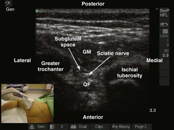
The greater trochanter and the ischial tuberosity are identified, and a line is drawn between these two landmarks. The US transducer is placed parallel to this line, with its orientation marker directed toward the greater trochanter to obtain a transverse scan of the sciatic nerve and the subgluteal space. It may be necessary to slide the transducer slightly cephalad or caudad before an optimal image of the sciatic nerve in the subgluteal space can be obtained. On a sonogram, the subgluteal space is seen as a hypoechoic area between the hyperechoic epimysium of the gluteus maximus and quadratus femoris muscle (see Fig. 42-32) extending from the greater trochanter laterally to the ischial tuberosity medially.88,89 The subgluteal space is not so well delineated in young children and is better visualized in older children. The sciatic nerve is seen as an oval or triangular hyperechoic structure within the subgluteal space (see Fig. 42-32). The medial limit of the space is obscured by the attachments of the semimembranosus, semitendinosus, and biceps femoris muscles to the ischial tuberosity. Pulsationfs of the inferior gluteal artery often can be detected medial to the sciatic nerve on the sonogram.
The block needle is inserted using in-plane technique from the ischial tuberosity side and advanced slowly toward the sciatic nerve. Once the block needle is deemed to be in the subgluteal space, the position is confirmed by injecting 1 to 3 mL of saline through the needle and observing a distention of the subgluteal space (i.e., separation of the epimysium of the gluteus maximus and quadratus femoris muscle) on the US image (Fig. 42-33). However, if the test injection of saline is seen to spread posterior to the epimysium of the gluteus maximus muscle, it indicates that the tip of the needle is not in the subgluteal space. The needle should be reoriented and advanced a little farther until the typical distention of the subgluteal space to the saline test injection is seen. Occasionally, a subtle pop is felt when the needle tip traverses the epimysium of the gluteus maximus muscle and enters the subgluteal space. Local anesthetic is then injected in aliquots over 2 to 3 minutes while observing for the distention of the subgluteal space and the spread of local anesthetic in relation to the sciatic nerve. It is also easy to pass a catheter into the subgluteal space when a continuous sciatic nerve block is planned. Because the catheter is inserted into an anatomic space, the catheter is also more likely to stay in situ (see also Figs. 41-28, 41-29, and 41-31, and Chapter 41 for landmark-based techniques).
Sciatic Nerve Block at the Popliteal Fossa
The sciatic nerve block at the popliteal fossa is also referred to as the popliteal fossa block and is the preferred approach for sciatic nerve block in children undergoing foot surgery. The popliteal fossa is a diamond-shaped space lying behind the knee joint, the lower part of the femur, and the upper part of the tibia. It is bound superolaterally by the tendon of biceps femoris, superomedially by the tendon of semitendinosus and the semimembranosus, inferolaterally by the lateral head of gastrocnemius, and inferomedially by the medial head of gastrocnemius. The sciatic nerve enters the posterior aspect of the thigh at the lower border of the gluteus maximus and runs vertically downward to the apex of the superior triangle of the popliteal fossa, where it terminates by dividing into the tibial and the common peroneal nerve, usually 3 to 7 cm above the popliteal crease.90,91 The division of the sciatic nerve into its terminal branches may, however, take place anywhere above this level. This accounts for the occasional sparing of either division of the sciatic nerve after distal sciatic nerve block techniques using nerve stimulation.
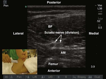
Although the classic teaching is to perform popliteal sciatic nerve block with the patient in the prone position, it is very commonly performed in children with the child in the supine position with the leg elevated by an assistant (Fig. 42-34). During US-guided popliteal sciatic nerve block the operator sits on the ipsilateral side facing the head of the patient and the US machine is positioned directly in front. In young children, a linear-array transducer (10-5 MHz) is adequate for imaging the sciatic nerve in the popliteal fossa. In the adolescent child or children with muscular thighs, a curved-array transducer (8-5 MHz) may be preferable. The transducer is positioned just above the apex of the upper triangle of the popliteal fossa in the transverse axis (see Fig. 42-34). It may be necessary to first scan for the sciatic nerve in the middle of the thigh and then trace it distally to the popliteal fossa, where the sciatic nerve is seen as a round, hyperechoic structure. Division of the sciatic nerve into the tibial and common peroneal nerve can also be visualized in children; location of this division varies widely among children. In the popliteal fossa and proximal to the popliteal crease, the tibial and common peroneal nerve are seen as hyperechoic structures superficial and lateral to the popliteal artery.
The block needle is inserted using in-plane technique from the lateral aspect of the thigh with its point of entry being anterior to the tendon of the biceps femoris (if it is palpable). This places the needle in the same orientation as for the lateral approach to the sciatic nerve at the popliteal fossa. The exact point of needle entry will depend on where the sciatic nerve is best visualized. The needle is gradually advanced under US guidance, and the tip is positioned just posterior to the sciatic nerve. This is confirmed by injecting 1 to 3 mL of saline through the needle, after which half of the calculated dose of local anesthetic is injected. The same process is repeated by repositioning the tip of the needle anterior to the sciatic nerve. This ensures that the local anesthetic spreads optimally around the sciatic nerve (see also Fig. 41-30 and Chapter 41 for landmark-guided techniques).
Truncal Blocks
Rectus Sheath Block
Rectus sheath block is the technique of injecting local anesthetic into the potential space between the rectus muscle and the posterior rectus sheath. This produces anesthesia of the ventral rami of the intercostal nerves as they traverse the rectus muscle to supply the skin of the anterior abdominal wall on either side of the midline. Because the seventh and eight intercostal nerves also provide motor innervation to the rectus abdominis muscle, a rectus sheath block at this level should also produce relaxation of the muscle. Bilateral rectus sheath blocks are frequently used in children to provide perioperative analgesia during umbilical and paraumbilical hernia.92 We have also found it to be useful for analgesia after laparoscopic procedures in children in whom the port insertion sites are close to the midline.
A linear-array transducer (13-10 MHz) with a small footprint (25 mm) is used for imaging in children (E-Fig. 42-2). The operator stands or sits on one side of the anesthetized child, and the US machine is positioned directly opposite on the contralateral side. The transducer is positioned in the longitudinal axis midway between the umbilicus and the xiphisternum. The rectus muscle is seen as a hypoechoic structure between the hyperechoic anterior and posterior rectus sheath (see E-Fig. 42-2). Deep to the posterior rectus sheath the hyperechoic peritoneum can be recognized by its typical peritoneal sliding movement and the “comet-tail” artifacts produced. The fibrous bands (tendinous insertions) in the rectus sheath can also be recognized in the longitudinal sonogram as hyperechoic areas on the anterior surface of the hypoechoic muscle that do not traverse the whole muscle belly.93,94 The linea alba can be recognized on a transverse sonogram, and the posterior deficiency of the rectus sheath is also readily recognized below the level of the arcuate line.

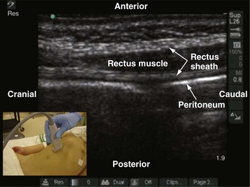
E-FIGURE 42-2 Longitudinal sonogram of the rectus muscle showing the anterior and posterior rectus sheath.
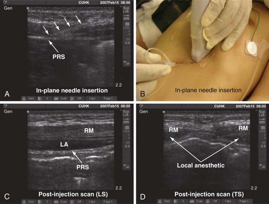
The block needle is inserted using in-plane technique in a caudal to cranial direction (E-Fig. 42-3). When the tip of the needle is visualized in the potential space between the rectus muscle and the posterior rectus sheath, a test injection of saline (1 to 3 mL) is performed to confirm the longitudinal spread of the injectate between the muscle and the rectus sheath and the widening of the space (see E-Fig. 42-3, C and D). Injection into the muscle will offer resistance to injection and is readily recognized in the sonogram. The needle should be repositioned, and the typical spread of the test injection under the rectus muscle should be confirmed before a calculated dose of the local anesthetic is injected. For umbilical hernia surgery, bilateral rectus sheath blocks are performed just above the umbilicus on either side (see also Fig. 41-16 and Chapter 41 for landmark-guided techniques).

Ilioinguinal and Iliohypogastric Nerve Blocks
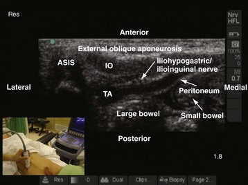
Ilioinguinal and iliohypogastric nerve blocks are used to provide analgesia after inguinal hernia repair, orchidopexy, or hydrocele surgery. The analgesia is comparable to caudal epidural analgesia, and it offers the advantage of not affecting micturition after surgery,95 making it ideal for analgesia in children undergoing an outpatient procedure. Currently, anatomic landmarks and tactile sensations are relied on to perform the block,95 which unfortunately can result in failure in up to 20% to 30% of cases. Moreover, it can also lead to complications such as femoral nerve palsy,96,97 pelvic hematoma,98 and bowel perforation.99 A US-guided ilioinguinal iliohypogastric nerve block has been described in children.21,100 Compared with the traditional landmark-based method, US-guided ilioinguinal iliohypogastric nerve block is accomplished more accurately, using smaller volumes of local anesthetic, and has a greater success rate.
A linear-array transducer (13-10 MHz) is used for the imaging and the ilioinguinal and iliohypogastric nerves, which are best visualized close to the ASIS. The operator stands on the ipsilateral side to be blocked, and the US machine is positioned directly opposite on the contralateral side. The transducer is positioned close to the ASIS and parallel to a line joining the ASIS and the umbilicus (Fig. 42-35). The ilioinguinal and iliohypogastric nerves are identified as two small, rounded structures lying side by side between the internal oblique and transversus abdominis muscle (see Fig. 42-35). The external oblique is frequently identified only as a hyperechoic aponeurotic layer at the point of needle insertion. Deep to the transversus abdominis muscle the peritoneum and the bowel are also visualized (see Fig. 42-35).
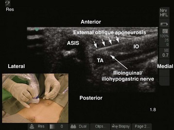
The block needle is inserted in the long axis (in-plane) of the US beam in a medial to lateral direction (Fig. 42-36). We prefer this orientation because it facilitates visualization of the needle (in-plane) and, in the event that the needle is inadvertently inserted too deep, further passage is obstructed by the iliac bone, thus reducing the potential for a major complication such as bowel perforation. When the tip of the needle is close to the two nerves, a test injection is performed with 0.5 to 1 mL of normal saline. Correct position of the needle tip is confirmed by observing the widening of the tissue plane between the internal oblique and the transversus abdominis muscle. A calculated dose of a long-acting local anesthetic (0.2 mL/kg) is then injected through the needle, and the spread of the local anesthetic to both nerves is visualized (see also Fig. 41-14 and Chapter 41 for landmark-guided techniques).
Transversus Abdominis Plane (TAP) Block
Local anesthetic injected into the TAP plane produce sensorimotor blockade (segmental) of the abdominal wall, and two techniques, the posterior TAP block and subcostal TAP block, have been described.101,102 In the posterior TAP block the local anesthetic is injected in the TAP plane between the iliac crest and the costal margin, and during a subcostal TAP block the local anesthetic is injected into the TAP plane just below the costal margin at the midclavicular line. Anesthesia and analgesia produced by a TAP block is unilateral; thus it is useful for surgical procedures (e.g., orchidopexy, herniotomy, appendicectomy) in which the incision does not cross the midline. Bilateral TAP blocks are indicated for abdominal surgical procedures in which the surgical incision is in the midline or across the midline. It is also the authors’ practice to perform bilateral TAP blocks for laparoscopic procedures. Because TAP blocks do not produce visceral analgesia, they should be used as part of a multimodal analgesic regimen for perioperative analgesia. Currently, published data on the use of TAP blocks for perioperative analgesia in children are limited101,103 but may be useful as an alternative when central neuraxial blocks are contraindicated (e.g., in children with underlying coagulopathy or spinal dysraphism).
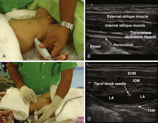
For a posterior TAP block, a high-frequency linear array transducer (15-7 MHz) is placed midway between the iliac crest and the costal margin along the midaxillary line (Fig. 42-37, A). For infants and young children, a linear transducer with a small footprint (25 mm) is preferred. The operator stands or sits on one side of the anesthetized child, and the US machine is positioned directly opposite on the contralateral side. The various layers of the abdominal wall are identified on the sonogram (see Fig. 42-37, B). From superficial to deep, they include a layer of subcutaneous tissue and fat and the three abdominal muscles with their fascial layers (i.e., the external oblique, internal oblique, and the transversus abdominis muscles, respectively). Deep to the transversus abdominis muscle the hypoechoic peritoneum is also visualized (see Fig. 42-37, B). The block needle (50 mm) is inserted 1 to 2 cm medial to the medial edge of the ultrasound transducer (Fig. 42-37, C ), depending on the depth at which the TAP is located (can be determined using the electronic caliper in the US system), and in the plane of the US beam. Because the abdominal wall in infants and young children is relatively thin, and to avoid inadvertent deep needle insertion and visceral puncture it is the authors’ practice to initially insert the block needle directed toward the US transducer rather than in an anteroposterior direction. Once the needle tip penetrates the skin and enters the abdominal muscle, it is redirected and slowly advanced under direct vision and penetration of the tip through the external oblique and internal oblique muscles, and finally the TAP is identified between the internal oblique and transversus abdominis muscles. A test injection (1 mL) of saline is performed to confirm correct needle placement in the TAP, which is indicated by distention of the TAP by the hypoechoic fluid. A calculated dose of a long-acting local anesthetic (0.2 mL/kg) is then injected through the needle, while distention of the TAP is visualized in realtime (see Fig. 42-37, D).
Thoracic Paravertebral Block
Thoracic paravertebral block is the technique of injecting local anesthetic alongside the thoracic vertebra close to the intervertebral foramen.104 This produces ipsilateral, segmental, somatic, and sympathetic nerve blockade that is effective for relieving postoperative pain of unilateral origin from the chest105 and abdomen.106 Traditionally, thoracic paravertebral block is performed using surface anatomic landmarks106 or a catheter is placed in the paravertebral space under direct vision during thoracic surgery (see Chapter 41).105 Currently, no published data exist on US-guided thoracic paravertebral block in children, although there are several reports in adults.107,108 The following section describes how the authors perform real-time, in-plane US-guided single-shot thoracic paravertebral block and paravertebral catheter placement in young infants.
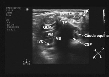
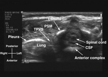
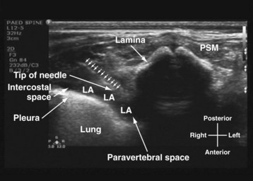
US-guided thoracic paravertebral block is performed with the child in the lateral position and with the side to be blocked uppermost. The operator sits or stands behind the child, and the US machine is positioned directly in front on the opposite side of the operating table. In most children a 15-6–MHz linear array transducer is adequate for imaging the paravertebral anatomy. However, a high-frequency linear array transducer with a small footprint (25 mm) is ideal for US-guided thoracic paravertebral block in neonates and young infants. For a US-guided thoracic paravertebral block for thoracotomy, the US transducer is placed at the midthoracic region and a transverse scan of the thoracic paravertebral region is performed with the orientation marker directed laterally. On a transverse sonogram of the thoracic paravertebral region and with the US beam being insonated between two adjacent ribs, the paraspinal muscles are identified as hypoechoic structures on either side of the midline and posterior to the spinal osseous elements (Fig. 42-38). The spinous process and lamina are identified as hyperechoic structures. Because the posterior spinal elements are cartilaginous in neonates and young infants, the acoustic window for imaging is relatively large and it is possible to visualize the neuraxial elements in the same transverse sonogram (see Fig. 42-38). Anterior to the lamina and transverse process the pleura can be visualized as a hyperechoic structure that moves synchronously with respiration or ventilation (see Fig. 42-38). A hypoechoic triangular space may also be visualized lateral to the paravertebral region and posterior to the pleura, which represents the apex of the thoracic paravertebral space (see Fig. 42-38).
For a US-guided thoracic paravertebral block, the block needle (50 mm) is inserted lateral to the US transducer and advanced toward the apical part of the paravertebral space in the plane of the US beam. The advancing needle is visualized in real time, and entry into the apex of the thoracic paravertebral space is confirmed using a test bolus injection (1 mL) of saline. Correct placement of the needle in the paravertebral space is indicated by anterior displacement of the parietal pleura, distention of the paravertebral space, and increased echogenicity of the parietal pleura (Fig. 42-39). A calculated dose of local anesthetic (0.2 mL/kg) is then injected with the needle in situ before a catheter is inserted through the needle, leaving approximately 2 cm of catheter in situ if a continuous thoracic paravertebral block is planned (see also Figs. 41-17, 41-18, and Chapter 41 for landmark-guided techniques).
Spinal Sonography and Central Neuraxial Blocks
Since the early 1980s, spinal ultrasonography has been used as a diagnostic screening tool in neonates and infants suspected of spinal dysraphism and for detecting spinal tumors, vascular malformations, and trauma.109,110 Today it is considered the first-line screening test for spinal dysraphism, with a diagnostic sensitivity comparable to that of MRI. Spinal ultrasonography is possible in neonates and infants because the incomplete ossification of the predominantly cartilaginous posterior spinal elements creates an acoustic window that allows the transmission of the US beam. The overall visibility of neuraxial structures decreases with age.109 Neuraxial structures are best visualized in neonates and infants younger than 3 months of age; progressive ossification of the posterior spinal elements makes detailed sonographic evaluation of the spine difficult beyond 6 months of age unless the child has a persistent posterior spinal defect.111 Some reports have demonstrated that neuraxial structures can be visualized in older children, although their details are limited. The overall visibility of neuraxial structures also decreases as one progresses up the spine, with the best visibility in the sacral level followed by the lumbar and then at the thoracic level.
In diagnostic radiology, spinal US is most frequently performed with the child in the prone position, whereas in an anesthetized child it is generally performed with the child in the lateral position. Because the neuraxial structures are relatively superficial in children, they are best visualized using high-frequency (10-5 MHz) transducers, which also produce better images than sector transducers. Scans are obtained in both the transverse (axial) and longitudinal (sagittal) axes, and they are performed either through the midline or parallel and lateral (paramedian) to the spinous processes. The paramedian scan is preferable in older children because it avoids the ossified spinous processes that can interfere with US transmission. In neonates and young infants, the spinal canal can be scanned with the transducer placed directly over the spinous processes (i.e., a median longitudinal scan). Beyond this age group a paramedian longitudinal scan provides the best overall view of neuraxial structures.112–114
On a longitudinal sonogram, the neonatal spinal cord is seen as a hypoechoic tubular structure with hyperechoic anterior and posterior walls (Fig. 42-40). A thin strip of variable intense echo, “the central echo complex” (see Fig. 42-40), extends longitudinally through the center of the spinal cord and represents the area between the myelinated ventral white commissure and the central portion of the anterior median fissure. This produces the “triplet echoes” that are characteristic of the spinal cord at all levels (see Fig. 42-40). The diameter of the spinal cord varies, being largest in the cervical and lumbar regions and smallest at the thoracic region. Anterior and posterior to the spinal cord are two well-defined linear and hyperechoic echoes that represent the arachnoid-dural layer (see Fig. 42-40). The ligamentum flavum, which is relevant for epidural access, is also readily visualized in young children and appears less echogenic than the dura (E-Fig. 42-4). The dural layers taper distally to close the thecal sac at the S2 level. The epidural space is the hypoechoic area between the dura and the ligamentum flavum (see E-Fig. 42-4), and arterial pulsations also may be visible on US between these two layers. The cerebrospinal fluid (CSF) surrounds the spinal cord as an anechoic layer between the dura and spinal cord (E-Fig. 42-5). The vertebral bodies are seen as echogenic structures anterior to the spinal cord. The spinal cord tapers distally to form the conus medullaris (Fig. 42-41) at the level of first and second lumbar vertebral bodies. The conus medullaris is continuous with the filum terminale, which extends into the sacral canal as a hyperechoic structure. It is surrounded by the roots of the cauda equina, which appear as multiple parallel echogenic lines surrounding the filum terminale (E-Fig. 42-6). Differentiation of the filum terminale from the roots of the cauda equina can sometimes be difficult. The cauda equina typically lies in the anterior half of the spinal canal when the child is in the prone position, but it moves freely within the CSF with change in position and with crying. Slight anteroposterior movement of the spinal cord, superimposed on the arterial pulsations, is commonly seen during real-time imaging.
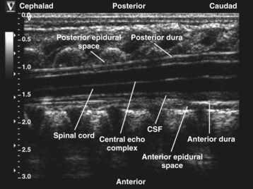
FIGURE 42-40 Longitudinal paramedian sonogram of the thoracic spine in a neonate. CSF, Cerebrospinal fluid.
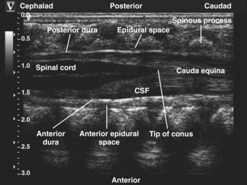


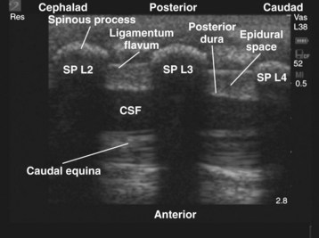
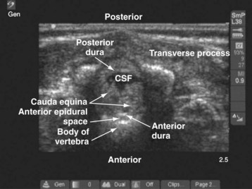
E-FIGURE 42-5 Transverse sonogram of the lumbar spine in a neonate showing the cauda equina. CSF, Cerebrospinal fluid.
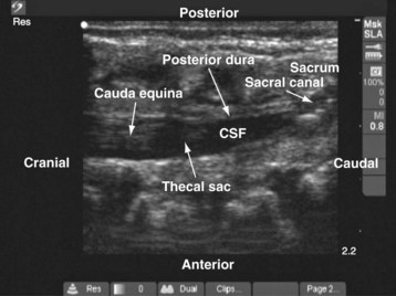
E-FIGURE 42-6 Longitudinal sonogram of the sacrum showing the tapered end of the thecal sac. CSF, Cerebrospinal fluid.
On a transverse (axial) sonogram, the spinal cord is seen as a round or oval hypoechoic structure, with its bright central echo complex (Fig. 42-42). The spinal cord is fixed laterally by the dentate ligament (see Fig. 42-42), which represents the transversely oriented, echogenic arachnoid duplications that are seen in parts of the thoracic spinal canal. Paired (ventral and dorsal) echogenic nerve roots are seen below the L2 level. Farther caudally in the lumbar region, a transverse scan shows the filum terminale surrounded by the nerve roots of the cauda equina (E-Fig. 42-7). The arachnoid–dura mater complex is hyperechoic and forms the anterior and posterior border of the subarachnoid space with the anechoic CSF and the spinal cord in the thoracic region (see Fig. 42-42) and the cauda equina in the lumbar region (see E-Fig. 42-7). The vertebral bodies are the hyperechoic structures anterior to the spinal canal. The vertebral arches are also echogenic and cast an acoustic shadow anteriorly (see E-Fig. 42-7). The paraspinal muscles appear hypoechoic on US.
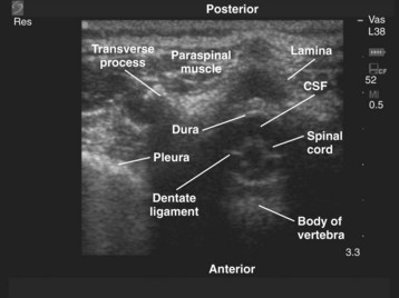

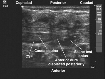
Caudal Epidural Anesthesia
Single-shot caudal epidural injection is the most frequently used regional anesthetic technique in children and almost always is used in combination with general anesthesia for surgery involving the lower thoracic, lumbar, and sacral dermatomes.115 Several methods are used to perform a caudal epidural injection.
Detecting the characteristic pop or give as the needle traverses the sacrococcygeal ligament to enter the caudal epidural space is by far the most commonly used method in children.115,116 However, even in experienced hands it can result in failure, and the overall failure rate varies between 2.8% and 11%.117 US has been used to guide caudal epidural injection in children.118,119 The correct position of a needle or catheter in the caudal epidural space is confirmed by real-time US visualization of the needle in the sacral canal or by observing dural displacement after a saline test bolus (0.2 to 0.3 mL/kg to a maximum of 10 mL) injection.
The anesthetized child is positioned in the lateral position with the knee and hips flexed. The operator sits or stands behind the child, and the US machine is positioned directly in front. A linear-array transducer (13-10 MHz) is used to image the sacrum. A transducer with a wide footprint is preferable because it allows a greater length of the spine to be examined in a single view. The transducer is initially positioned directly over the sacral cornua in the transverse axis (Fig. 42-43). On a transverse sonogram at the level of the sacral hiatus, the sacral cornua are seen as two hyperechoic reverse U-shaped structures, one on either side of the midline. Connecting the two sacral cornua and deep to the skin and subcutaneous tissue is a hyperechoic band, the sacrococcygeal ligament (see Fig. 42-43). Anterior to the sacrococcygeal ligament is another linear hyperechoic structure, which represents the posterior surface of the sacrum. The hypoechoic area between the sacrococcygeal ligament and the bony posterior surface of the sacrum is the sacral hiatus (see Fig. 42-43). The two sacral cornua and the posterior surface of the sacrum produce a US image that we refer to as the “frog-eye sign” because of its resemblance to the eyes of a frog (see Fig. 42-43). On a longitudinal sonogram of the sacrum, the sacrococcygeal ligament, the base of the sacrum, and the sacral hiatus can be clearly seen (E-Fig. 42-8). In neonates and young infants the tapered end of the thecal sac with CSF, the anterior and posterior epidural space filled with fat, and the cauda equina may be visualized in the sacral canal (see E-Fig. 42-8).
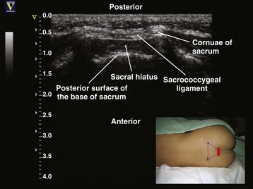

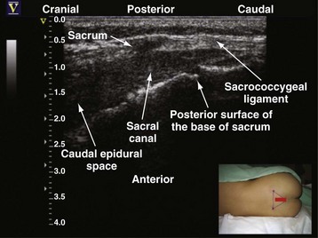
For US-guided caudal epidural injection, either in-plane or out-of-plane technique can be used. We prefer the in-plane approach, and the needle is advanced under real-time guidance into the sacral canal through the sacrococcygeal ligament. During insertion, the needle is maintained at an angle (approximately 20 degrees) so that it is parallel to the posterior surface of the sacrum. Correct position of the needle in the caudal epidural space is confirmed objectively by performing a test bolus injection of saline and observing in real time the displacement of the dura (E-Fig. 42-9).119,120 Anterior displacement of the posterior dura is more frequently seen than posterior displacement of the anterior dura. If dural displacement is not seen in the US image, it implies that the needle or catheter is not in the correct position, the needle or catheter is not in the plane of US imaging, or the needle is intravascular. The needle should be withdrawn and the procedure repeated until the typical dural displacement is visualized. The calculated dose of local anesthetic is then injected in aliquots. The cephalad spread of the local anesthetic within the epidural space also can be visualized in real time. Depending on the volume of local anesthetic injected, progressive widening of the epidural space and a resultant compression of the thecal sac occur (see E-Fig. 42-9). These changes are visualized in the sacral canal and at the lumbar and thoracic levels. In some cases the thecal sac is almost completely obliterated in the sacral and lumbar region (see E-Fig. 42-9). Because the compression and obliteration of the thecal sac occurs in a caudal to cranial direction, it indicates that there is a net cranial displacement of CSF.

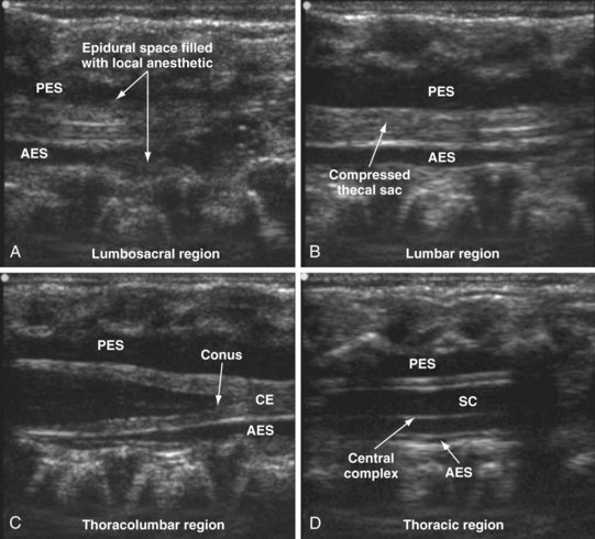
US guidance during a caudal epidural injection in children offers several advantages. It is safe, noninvasive, radiation free, simple, and quick to perform; it provides real-time images that are easy to interpret; and, unlike the nerve stimulation technique, is not affected by the use of neuromuscular blocking drugs or epidural local anesthetics. Moreover, US can demonstrate the underlying caudal anatomy, which is useful in children with cutaneous markers of dysraphism when it can be used to screen the underlying spinal anatomy. Thus many children who may have otherwise been excluded from a caudal block can benefit from its effects. It is also a useful tool for teaching and learning of caudal anesthesia (see also Fig. 41-6 and Chapter 41 for landmark-guided techniques).
Epidural Catheterization
Continuous epidural analgesia via an indwelling epidural catheter is a well-established method of providing perioperative analgesia in children.121 The loss-of-resistance technique5,122 is the most frequently used method of identifying the epidural space. Although popular, this technique relies on the operator’s tactile sensation and can rarely result in dural puncture and serious neurologic complication, such as spinal cord injury. Alternative methods for identifying the epidural space in children have been described123 but have not gained widespread acceptance. Epidural catheters have been successfully placed in young children under US guidance.122,124 Compared with the traditional loss-of-resistance method, when epidural catheterization is performed using the loss-of-resistance method in conjunction with US guidance, fewer bony contacts occur during the procedure and the time required for catheter placement is reduced. The spread of local anesthetic in the epidural space can also be visualized in real time. In addition, the underlying anatomy and the depth from the skin to the ligamentum flavum, dura, and epidural space can be assessed before needle insertion. However, epidural catheterization under US guidance requires two anesthesiologists who are familiar with epidural anesthesia and spinal sonography in children. The first anesthesiologist performs the scan in the longitudinal paramedian axis and maintains a steady image while the second anesthesiologist performs the needle insertion through the midline. Entry of the needle into the epidural space is confirmed by the loss of resistance to saline and observing the local sonographic changes resulting from the saline injection (i.e., anterior displacement of the posterior dura, widening of the epidural space, and compression of the thecal sac). US-guided epidural catheterization in young children is a very demanding procedure and requires a great deal of skill and dexterity. It should be undertaken only by pediatric anesthesiologists who have acquired adequate training and skill in US-guided regional anesthesia (see Chapter 41 for landmark-guided techniques).
Assessment of Indwelling Epidural Catheters
For optimal epidural anesthesia or analgesia, the epidural catheter tip must be located in the correct dermatomal level. This is often achieved by directly placing the catheter in the desired level via the lumbar or thoracic route. Even with this approach, and in particular when loss of resistance is used to locate the epidural space, it is not possible to determine with any certainty the exact location of the catheter tip. Epidurography can locate the catheter tip,125 but this exposes the child to radiation and the risk of anaphylaxis from the contrast medium (see Figure 41-7). An epidural catheter inserted via the caudal route can be advanced to the lumbar or thoracic epidural space. However, this is technically difficult in children older than 1 year of age,126 and even in children younger than 6 months of age, the catheter can be misplaced in the sacral, lumbar, and even the cervical region.127,128 Whether styleted epidural catheters are easier to advance from the caudal to the thoracic epidural space than nonstyleted ones is not known, although better success has been reported with styleted catheters.129 Even if a catheter is successfully advanced to the thoracic epidural space, radiographic confirmation is still required to confirm the position of the catheter tip.127 Electric nerve stimulation through an indwelling styleted epidural catheter and observation of myotomal contractions have been used to locate the position of the catheter tip.130 In experienced hands this technique has a success rate of 89%. However, this test cannot be performed if neuromuscular blocking drugs or local anesthetics have been administered. Epidural electrocardiography also can be used to locate the position of a thoracic epidural catheter131 and is not affected by the use of neuromuscular blocking drugs or local anesthetics in the epidural space. This method relies on matching the evolving electrocardiogram (ECG) recorded from the tip of a specially adapted epidural catheter, as it is advanced, to the surface ECG recorded at the target vertebral level. However, this method is not specific because even a subcutaneous electrocardiographic electrode at the same position relative to the heart will produce a similar electrocardiographic pattern.
US has been used to directly visualize the position of epidural catheters in children (E-Fig. 42-10).132,133 US localization is noninvasive, does not involve exposure to radiation or contrast medium, and is not affected by the use of neuromuscular blocking drugs or epidural local anesthetics. It also provides real-time images of the catheter during catheter insertion. However, not all epidural catheters or their tips can be identified using US, and it may be limited by the acoustic window available for scanning in children of different ages. Gently jiggling the catheter and observing tissue movement within the epidural space also has been used to facilitate epidural catheter localization.133 Injecting saline with air bubbles may improve catheter localization using US, but the use of air in the injectate can lead to inadvertent air embolism or a patchy block.134 Therefore it is suggested that observing surrogate markers such as the widening of the epidural space, dural displacement, and compression of the thecal sac, subsequent to a saline test injection, may be more accurate in locating the position of an epidural catheter in children.

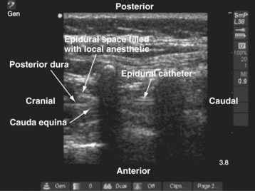
Education and Training
Learning US-guided nerve block techniques takes time and patience. The state of the art of regional anesthesia demands a high degree of manual dexterity and hand–eye coordination and an ability to conceptualize 2D information into a 3D image. In addition, to produce good-quality US images, the anesthesiologist must also possess a sound knowledge of anatomy, the physical principles of US, and musculoskeletal imaging. Therefore individuals who intend to perform US-guided regional anesthesia should start by learning the basics of US and US-guided interventions by attending a course or workshop and by working with individuals who already possess these skills. Initial experience of musculoskeletal scanning can also be acquired in volunteer situations, and US-guided interventions can be practiced using a US phantom.135–139 Once the basic skills are acquired, it is best to start by performing superficial peripheral nerve block procedures (e.g., axillary brachial plexus block, femoral and sciatic nerve block) under supervision before attempting deeper blocks (e.g., lumbar plexus block), which can be technically demanding even for an experienced operator. Whenever possible, it is advisable to use a peripheral nerve stimulator in conjunction with US during the learning phase of US-guided nerve blocks. With proficiency, it is possible to perform most techniques without nerve stimulation. Fortunately, the learning curve is steep140 and most anesthesiologists are able to acquire the required skills very quickly, probably owing to their inherent good hand–eye coordination and ability to think in three dimensions. It is preferable to perfect these techniques in adults or older children before performing them in young children. US-guided epidural techniques, other than single-shot caudal epidural injections, demand a high degree of skill and dexterity and should be performed only by anesthesiologists experienced in US-guided regional anesthesia.
Kapral S, Krafft P, Eibenberger K, et al. Ultrasound-guided supraclavicular approach for regional anesthesia of the brachial plexus. Anesth Analg. 1994;78:507–513.
La Grange P, Foster PA, Pretorius LK. Application of the Doppler ultrasound bloodflow detector in supraclavicular brachial plexus block. Br J Anaesth. 1978;50:965–967.
Marhofer P, Frickey N. Ultrasonographic guidance in pediatric regional anesthesia. I. Theoretical background. Paediatr Anaesth. 2006;16:1008–1018.
Roberts S. Ultrasonographic guidance in pediatric regional anesthesia. II. Techniques. Paediatr Anaesth. 2006;16:1112–1124.
1 Sumpelmann R, Munte S. Postoperative analgesia in infants and children. Curr Opin Anaesthesiol. 2003;16:309–313.
2 Ross AK, Eck JB, Tobias JD. Pediatric regional anesthesia: beyond the caudal. Anesth Analg. 2000;91:16–26.
3 Suresh S, Wheeler M. Practical pediatric regional anesthesia. Anesthesiol Clin North Am. 2002;20:83–113.
4 Khoo ST, Brown TC. Femoral nerve block: the anatomical basis for a single injection technique. Anaesth Intensive Care. 1983;11:40–42.
5 Shenouda PE, Cunningham BJ. Assessing the superiority of saline versus air for use in the epidural loss of resistance technique: a literature review. Reg Anesth Pain Med. 2003;28:48–53.
6 Sia S. A comparison of injection at the ulnar and the radial nerve in axillary block using triple stimulation. Reg Anesth Pain Med. 2006;31:514–518.
7 Klaastad O, Lilleås FG, Røtnes JS, et al. Magnetic resonance imaging demonstrates lack of precision in needle placement by the infraclavicular brachial plexus block described by Raj et al. Anesth Analg. 1999;88:593–598.
8 Chan VW. Nerve localization: seek but not so easy to find? Reg Anesth Pain Med. 2002;27:245–248.
9 Jenkins CR, Karmakar MK. An unusual complication of interscalene brachial plexus catheterization: delayed catheter migration. Br J Anaesth. 2005;95:535–537.
10 De Biasi P, Lupescu R, Burgun G, et al. Continuous lumbar plexus block: use of radiography to determine catheter tip location. Reg Anesth Pain Med. 2003;28:135–139.
11 Floch H, Naux E, Pham Dang C, et al. Computed tomography scanning of the sciatic nerve posterior to the femur: practical implications for the lateral midfemoral block. Reg Anesth Pain Med. 2003;28:445–449.
12 Gray AT. Ultrasound-guided regional anesthesia: current state of the art. Anesthesiology. 2006;104:368–373.
13 Marhofer P, Frickey N. Ultrasonographic guidance in pediatric regional anesthesia. I. Theoretical background. Paediatr Anaesth. 2006;16:1008–1018.
14 Roberts S. Ultrasonographic guidance in pediatric regional anesthesia. II. Techniques. Paediatr Anaesth. 2006;16:1112–1124.
15 De Andres J, Sala-Blanch X. Ultrasound in the practice of brachial plexus anesthesia. Reg Anesth Pain Med. 2002;27:77–89.
16 Tsui B, Suresh S. Ultrasound imaging for regional anesthesia in infants, children, and adolescents: a review of current literature and its application in the practice of extremity and trunk blocks. Anesthesiology. 2010;112:473–492.
17 Tsui BC, Suresh S. Ultrasound imaging for regional anesthesia in infants, children, and adolescents: a review of current literature and its application in the practice of neuraxial blocks. Anesthesiology. 2010;112:719–728.
18 Neal JM, Brull R, Chan VW, et al. The ASRA evidence-based medicine assessment of ultrasound-guided regional anesthesia and pain medicine: executive summary. Reg Anesth Pain Med. 2010;35(2 Suppl):S1–S9.
19 Antonakakis JG. Ultrasound-guided regional anesthesia for peripheral nerve blocks: an evidence-based outcome review. Anesthesiol Clin. 2011;29:179–191.
20 Marhofer P, Sitzwohl C, Greher M, et al. Ultrasound guidance for infraclavicular brachial plexus anaesthesia in children. Anaesthesia. 2004;59:642–646.
21 Willschke H, Marhofer P, Bosenberg A, et al. Ultrasonography for ilioinguinal/iliohypogastric nerve blocks in children. Br J Anaesth. 2005;95:226–230.
22 La Grange P, Foster PA, Pretorius LK. Application of the Doppler ultrasound bloodflow detector in supraclavicular brachial plexus block. Br J Anaesth. 1978;50:965–967.
23 Kapral S, Krafft P, Eibenberger K, et al. Ultrasound-guided supraclavicular approach for regional anesthesia of the brachial plexus. Anesth Analg. 1994;78:507–513.
24 Hangiandreou NJ. AAPM/RSNA physics tutorial for residents. Topics in US: B-mode US: basic concepts and new technology. RadioGraphics. 2003;23:1019–1033.
25 Wells PN. Ultrasound imaging. Phys Med Biol. 2006;51:R83–R88.
26 Aldrich JE. Basic physics of ultrasound imaging. Crit Care Med. 2007;35:S131–S137.
27 White DN, Hudson AC. The future of A-mode midline echo-encephalography: the development of automated techniques. Neurology. 1971;21:140–153.
28 Popp RL, Rubenson DS, Tucker CR, et al. Echocardiography: M-mode and two-dimensional methods. Ann Intern Med. 1980;93:844–856.
29 Gorg C, Riera-Knorrenschild J, Dietrich J. Pictorial review: colour Doppler ultrasound flow patterns in the portal venous system. Br J Radiol. 2002;75:919–929.
30 Boote EJ. AAPM/RSNA physics tutorial for residents. Topics in US: Doppler US techniques: concepts of blood flow detection and flow dynamics. RadioGraphics. 2003;23:1315–1327.
31 Kruskal JB, Newman PA, Sammons LG, et al. Optimizing Doppler and color flow US: application to hepatic sonography. RadioGraphics. 2004;24:657–675.
32 Chen P, Maklad N, Redwine M. Color and power Doppler imaging of the kidneys. World J Urol. 1998;16:41–45.
33 Smith RS, Fry WR. Ultrasound instrumentation. Surg Clin North Am. 2004;84:953–971.
34 Feigenbaum H, Armstrong WF, Ryan T, eds. Feigenbaum’s echocardiography, 6th ed, Philadelphia, Lippincott Williams & Wilkins, 2005:11–45.
35 Harness JK, Wisher DB. Ultrasound in Surgical Practice: Basic Principles and Clinical Applications. New York: Wiley-Liss; 2001. p. 21-32
36 Marhofer P, Schrögendorfer K, Koinig H, et al. Ultrasonographic guidance improves sensory block and onset time of three-in-one blocks. Anesth Analg. 1997;85:854–857.
37 Chan VW, Perlas A, Rawson R, Odukoya O. Ultrasound-guided supraclavicular brachial plexus block. Anesth Analg. 2003;97:1514–1517.
38 Sandhu NS, Capan LM. Ultrasound-guided infraclavicular brachial plexus block. Br J Anaesth. 2002;89:254–259.
39 Chapman GA, Johnson D, Bodenham AR. Visualisation of needle position using ultrasonography. Anaesthesia. 2006;61:148–158.
40 Schafhalter-Zoppoth I, McCulloch CE, Gray AT. Ultrasound visibility of needles used for regional nerve block: an in vitro study. Reg Anesth Pain Med. 2004;29:480–488.
41 Hebard S, Hocking G. Echogenic technology can improve needle visibility during ultrasound-guided regional anesthesia. Reg Anesth Pain Med. 2011;36:185–189.
42 Tsui BC, Kropelin B, Ganapathy S, et al. Dextrose 5% in water: fluid medium for maintaining electrical stimulation of peripheral nerves during stimulating catheter placement. Acta Anaesthesiol Scand. 2005;49:1562–1565.
43 Crass JR, van de Vegte GL, Harkavy LA. Tendon echogenicity: ex vivo study. Radiology. 1988;167:499–501.
44 Soong J, Schafhalter-Zoppoth I, Gray AT. The importance of transducer angle to ultrasound visibility of the femoral nerve. Reg Anesth Pain Med. 2005;30:505.
45 Loewy J. Sonoanatomy of the median, ulnar and radial nerves. Can Assoc Radiol J. 2002;53:33–38.
46 Martinoli C, Bianchi S, Dahmane M, et al. Ultrasound of tendons and nerves. Ear Radiol. 2002;12:44–55.
47 Walker FO. Imaging nerve and muscle with ultrasound. Suppl Clin Neurophysiology. 2004;57:243–254.
48 Petron’s P. Ultrasound of muscles. Ear Radiol. 2002;12:35–43.
49 Wernicke K. Ultrasound study of the pleura. Ear Radiol. 2000;10:1515–1523.
50 Beck S, Blockier PL, Less au KD. Real-time chest ultrasonography: a comprehensive review for the pulmonologist. Chest. 2002;122:1759–1773.
51 Coley BD. Pediatric chest ultrasound. Radiol Clin North Am. 2005;43:405–418.
52 Abramowitz JS. Technical advances in ultrasound equipment. Clin Obstat Gynéco. 2003;46:839–849.
53 Claudio M, Trinquart F, Evans DH, et al. Advances in ultrasound. Ear Radiol. 2002;12:7–18.
54 Whittingham TA. Tissue harmonic imaging. Eur Radiol. 1999;9:S323–S326.
55 Entrekin RR, Porter BA, Sillesen HH, et al. Real-time spatial compound imaging: application to breast, vascular, and musculoskeletal ultrasound. Semin Ultrasound CT MR. 2001;22:50–64.
56 Shapiro RS. Panoramic ultrasound of the thyroid. Thyroid. 2003;13:177–181.
57 Sites BD, Brull R, Chan VW, et al. Artifacts and pitfall errors associated with ultrasound-guided regional anesthesia. II. A pictorial approach to understanding and avoidance. Reg Anesth Pain Med. 2010;35(2 Suppl):S81–S92.
58 Stanley JH, Harrell B, Horger EO. Pseudoepidural reverberation artifact: a common ultrasound artifact in fetal cranium. J Clin Ultrasound. 1986;14:251–254.
59 Sandler MA, Madrazo BL, Walter R, et al. Ultrasound case of the day: duplication artifact (mirror image artifact). RadioGraphics. 1987;7:1025–1028.
60 Gray AT, Schafhalter-Zoppoth I. “Bayonet artifact” during ultrasound-guided transarterial axillary block. Anesthesiology. 2005;102:1291–1292.
61 Winnie AP. An “immobile needle” for nerve blocks. Anesthesiology. 1969;31:577–578.
62 Pande R, Pande M, Bhadani U, et al. Supraclavicular brachial plexus block as a sole anaesthetic technique in children: an analysis of 200 cases. Anaesthesia. 2000;55:798–802.
63 Amiri HR, Espandar R. Upper extremity surgery in younger children under ultrasound-guided supraclavicular brachial plexus block: a case series. J Child Orthop. 2010;4:315–319.
64 Tran de QH, Charghi R, Finlayson RJ. The “double bubble” sign for successful infraclavicular brachial plexus blockade. Anesth Analg. 2006;103:1048–1049.
65 Fisher P, Wilson SE, Brown M, et al. Continuous infraclavicular brachial plexus block in a child. Paediatr Anaesth. 2006;16:884–886.
66 Bigeleisen P, Wilson M. A comparison of two techniques for ultrasound guided infraclavicular block. Br J Anaesth. 2006;96:502–507.
67 Sandhu NS, Bahniwal CS, Capan LM. Feasibility of an infraclavicular block with a reduced volume of lidocaine with sonographic guidance. J Ultrasound Med. 2006;25:51–56.
68 Arcand G, Williams SR, Chouinard P, et al. Ultrasound-guided infraclavicular versus supraclavicular block. Anesth Analg. 2005;101:886–890.
69 Porter JM, McCartney CJ, Chan VW. Needle placement and injection posterior to the axillary artery may predict successful infraclavicular brachial plexus block: a report of three cases. Can J Anaesth. 2005;52:69–73.
70 Marhofer P, Sitzwohl C, Greher M, Kapral S. Ultrasound guidance for infraclavicular brachial plexus anaesthesia in children. Anaesthesia. 2004;59:642–646.
71 Ootaki C, Hayashi H, Amano M. Ultrasound-guided infraclavicular brachial plexus block: an alternative technique to anatomical landmark-guided approaches. Reg Anesth Pain Med. 2000;25:600–604.
72 Sites BD, Beach ML, Spence BC, et al. Ultrasound guidance improves the success rate of a perivascular axillary plexus block. Acta Anaesthesiol Scand. 2006;50:678–684.
73 Casati A, Danelli G, Baciarello M, et al. A prospective, randomized comparison between ultrasound and nerve stimulation guidance for multiple injection axillary brachial plexus block. Anesthesiology. 2007;106:992–996.
74 Chan VW, Perlas A, McCartney CJ, et al. Ultrasound guidance improves success rate of axillary brachial plexus block. Can J Anaesth. 2007;54:176–182.
75 Retzl G, Kapral S, Greher M, et al. Ultrasonographic findings of the axillary part of the brachial plexus. Anesth Analg. 2001;92:1271–1275.
76 Schafhalter-Zoppoth I, Gray AT. The musculocutaneous nerve: ultrasound appearance for peripheral nerve block. Reg Anesth Pain Med. 2005;30:385–390.
77 Spence BC, Sites BD, Beach ML. Ultrasound-guided musculocutaneous nerve block: a description of a novel technique. Reg Anesth Pain Med. 2005;30:198–201.
78 McCartney CJ, Xu D, Constantinescu C, et al. Ultrasound examination of peripheral nerves in the forearm. Reg Anesth Pain Med. 2007;32:434–439.
79 Gray AT, Schafhalter-Zoppoth I. Ultrasound guidance for ulnar nerve block in the forearm. Reg Anesth Pain Med. 2003;28:335–339.
80 Kirchmair L, Enna B, Mitterschiffthaler G, et al. Lumbar plexus in children: a sonographic study and its relevance to pediatric regional anesthesia. Anesthesiology. 2004;101:445–450.
81 Farny J, Drolet P, Girard M. Anatomy of the posterior approach to the lumbar plexus block. Can J Anaesth. 1994;41:480–485.
82 Kirchmair L, Entner T, Kapral S, Mitterschiffthaler G. Ultrasound guidance for the psoas compartment block: an imaging study. Anesth Analg. 2002;94:706–710.
83 Karmakar MK, Ho AM, Li X, et al. Ultrasound-guided lumbar plexus block through the acoustic window of the lumbar ultrasound trident. Br J Anaesth. 2008;100:533–537.
84 Sites BD, Beach M, Gallagher JD, et al. A single injection ultrasound-assisted femoral nerve block provides side effect-sparing analgesia when compared with intrathecal morphine in patients undergoing total knee arthroplasty. Anesth Analg. 2004;99:1539–1543.
85 Tsai PB, Karnwal A, Kakazu C, et al. Efficacy of an ultrasound-guided subsartorial approach to saphenous nerve block: a case series. Can J Anaesth. 2010;57:683–688.
86 Manickam B, Perlas A, Duggan E, et al. Feasibility and efficacy of ultrasound-guided block of the saphenous nerve in the adductor canal. Reg Anesth Pain Med. 2009;34:578–580.
87 Mansour NY. Sub-sartorial saphenous nerve block with the aid of nerve stimulator. Reg Anesth. 1993;18:266–268.
88 Oberndorfer U, Marhofer P, Bösenberg A, et al. Ultrasonographic guidance for sciatic and femoral nerve blocks in children. Br J Anaesth. 2007;98:797–801.
89 Karmakar MK, Kwok WH. Ultrasound-guided sciatic nerve block: description of a new approach at the subgluteal space. Br J Anaesth. 2007;98:390–395.
90 Gray AT, Huczko EL, Schafhalter-Zoppoth I. Lateral popliteal nerve block with ultrasound guidance. Reg Anesth Pain Med. 2004;29:507–509.
91 Chan VW, Nova H, Abbas S, et al. Ultrasound examination and localization of the sciatic nerve: a volunteer study. Anesthesiology. 2006;104:309–314.
92 Isaac LA, McEwen J, Hayes JA, Crawford MW. A pilot study of the rectus sheath block for pain control after umbilical hernia repair. Paediatr Anaesth. 2006;16:406–409.
93 Ferguson S, Thomas V, Lewis I. The rectus sheath block in paediatric anaesthesia: new indications for an old technique? Paediatr Anaesth. 1996;6:463–466.
94 Willschke H, Bösenberg A, Marhofer P, et al. Ultrasonography-guided rectus sheath block in paediatric anesthesia: a new approach to an old technique. Br J Anaesth. 2006;97:244–249.
95 Markham SJ, Tomlinson J, Hain WR. Ilioinguinal nerve block in children: a comparison with caudal block for intra and postoperative analgesia. Anaesthesia. 1986;41:1098–1103.
96 Shivashanmugam T, Kundra P, Sudhakar S. Iliac compartment block following ilioinguinal iliohypogastric nerve block. Paediatr Anaesth. 2006;16:1084–1086.
97 Derrick JL, Aun CS. Transient femoral nerve palsy after ilioinguinal block. Anaesth Intensive Care. 1996;24:115.
98 Vaisman J. Pelvic hematoma after an ilioinguinal nerve block for orchialgia. Anesth Analg. 2001;92:1048–1049.
99 Frigon C, Mai R, Valois-Gomez T, et al. Bowel hematoma following an iliohypogastric-ilioinguinal nerve block. Paediatr Anaesth. 2006;16:993–996.
100 Eichenberger U, Greher M, Kirchmair L, et al. Ultrasound-guided blocks of the ilioinguinal and iliohypogastric nerve: accuracy of a selective new technique confirmed by anatomical dissection. Br J Anaesth. 2006;97:238–243.
101 Hebbard PD, Barrington MJ, Vasey C. Ultrasound-guided continuous oblique subcostal transversus abdominis plane blockade: description of anatomy and clinical technique. Reg Anesth Pain Med. 2010;35:436–441.
102 Lee TH, Barrington MJ, Tran TM, et al. Comparison of extent of sensory block following posterior and subcostal approaches to ultrasound-guided transversus abdominis plane block. Anaesth Intensive Care. 2010;38:452–460.
103 Sandeman DJ, Bennett M, Dilley AV, et al. Ultrasound-guided transversus abdominis plane blocks for laparoscopic appendicectomy in children: a prospective randomized trial. Br J Anaesth. 2011;106:882–886.
104 Karmakar MK. Thoracic paravertebral block. Anesthesiology. 2001;95:771–780.
105 Karmakar MK, Booker PD, Franks R, et al. Continuous extrapleural paravertebral infusion of bupivacaine for post-thoracotomy analgesia in young infants. Br J Anaesth. 1996;76:811–815.
106 Berta E, Spanhel J, Smakal O, et al. Single injection paravertebral block for renal surgery in children. Paediatr Anaesth. 2008;18:593–597.
107 Cowie B, McGlade D, Ivanusic J, et al. Ultrasound-guided thoracic paravertebral blockade: a cadaveric study. Anesth Analg. 2010;110:1735–1739.
108 Luyet C, Herrmann G, Ross S, et al. Ultrasound-guided thoracic paravertebral puncture and placement of catheters in human cadavers: where do catheters go? Br J Anaesth. 2011;106:246–254.
109 Dick EA, de Bruyn R. Ultrasound of the spinal cord in children: its role. Eur Radiol. 2003;13:552–562.
110 Dick EA, Patel K, Owens CM, et al. Spinal ultrasound in infants. Br J Radiol. 2002;75:384–392.
111 Marhofer P, Bösenberg A, Sitzwohl C, et al. Pilot study of neuraxial imaging by ultrasound in infants and children. Paediatr Anaesth. 2005;15:671–676.
112 Unsinn KM, Geley T, Freund MC, et al. US of the spinal cord in newborns: spectrum of normal findings, variants, congenital anomalies, and acquired diseases. RadioGraphics. 2000;20:923–938.
113 Zieger M, Dörr U. Pediatric spinal sonography. I. Anatomy and examination technique. Pediatr Radiol. 1988;18:9–13.
114 Gusnard DA, Naidich TP, Yousefzadeh DK, et al. Ultrasonic anatomy of the normal neonatal and infant spine: correlation with cryomicrotome sections and CT. Neuroradiology. 1986;28:493–511.
115 Bramwell RG, Bullen C, Radford P. Caudal block for postoperative analgesia in children. Anaesthesia. 1982;37:1024–1028.
116 Silvani P, Camporesi A, Agostino MR, et al. Caudal anesthesia in pediatrics: an update. Minerva Anestesiol. 2006;72:453–459.
117 Dalens B, Hasnaoui A. Caudal anesthesia in pediatric surgery: success rate and adverse effects in 750 consecutive patients. Anesth Analg. 1989;68:83–89.
118 Park JH, Koo BN, Kim JY, et al. Determination of the optimal angle for needle insertion during caudal block in children using ultrasound imaging. Anaesthesia. 2006;61:946–949.
119 Edward R. Ultrasound-guided caudal epidural injection. Anesthesiology. 2005;102:693.
120 Chen CP, Tang SF, Hsu TC, et al. Ultrasound guidance in caudal epidural needle placement. Anesthesiology. 2004;101:181–184.
121 Tobias JD. New insights into regional anesthesia in children: new techniques and new indications. Curr Opin Anaesthesiol. 2001;14:345–352.
122 Willschke H, Marhofer P, Bösenberg A, et al. Epidural catheter placement in children: comparing a novel approach using ultrasound guidance and a standard loss-of-resistance technique. Br J Anaesth. 2006;97:200–207.
123 Yamashita M, Tsuji M. Identification of the epidural space in children: the application of a micro-drip infusion set. Anaesthesia. 1991;46:872–874.
124 Rapp HJ, Folger A, Grau T. Ultrasound-guided epidural catheter insertion in children. Anesth Analg. 2005;101:333–339.
125 Asato F, Goto F. Radiographic findings of unilateral epidural block. Anesth Analg. 1996;83:519–522.
126 Blanco D, Llamazares J, Martínez-Mora J, et al. Thoracic epidural anesthesia by the caudal route in pediatric anesthesia: age is a limiting factor. Rev Esp Anestesiol Reanim. 1994;41:214–216.
127 Valairucha S, Seefelder C, Houck CS. Thoracic epidural catheters placed by the caudal route in infants: the importance of radiographic confirmation. Paediatr Anaesth. 2002;12:424–428.
128 Gunter JB, Eng C. Thoracic epidural anesthesia via the caudal approach in children. Anesthesiology. 1992;76:935–938.
129 Tsui BC, Usher A, Kulkarni PR, et al. Thoracic epidural catheters via the caudal and lumbar approaches using styletted multiple port catheters in pediatric patients: a report of three cases. Acta Anaesthesiol Scand. 2006;50:514–517.
130 Tsui BC, Gupta S, Finucane B. Confirmation of epidural catheter placement using nerve stimulation. Can J Anaesth. 1998;45:640–644.
131 Tsui BC, Seal R, Koller J. Thoracic epidural catheter placement via the caudal approach in infants by using electrocardiographic guidance. Anesth Analg. 2002;95:326–330.
132 Chawathe MS, Jones RM, Gildersleve CD, et al. Detection of epidural catheters with ultrasound in children. Paediatr Anaesth. 2003;13:681–684.
133 Roberts SA, Galvez I. Ultrasound assessment of caudal catheter position in infants. Paediatr Anaesth. 2005;15:429–432.
134 Dalens B, Bazin JE, Haberer JP. Epidural bubbles as a cause of incomplete analgesia during epidural anesthesia. Anesth Analg. 1987;66:679–683.
135 Xu D, Abbas S, Chan VW. Ultrasound phantom for hands-on practice. Reg Anesth Pain Med. 2005;30:593–594.
136 Chantler J, Gale L, Weldon O. A reusable ultrasound phantom. Anaesthesia. 2004;59:1145–1146.
137 Nicholson RA, Crofton M. Training phantom for ultrasound guided biopsy. Br J Radiol. 1997;70:192–194.
138 Li JW, Karmakar MK, Li X, et al. Gelatin-agar lumbosacral spine phantom: a simple model for learning the basic skills required to perform real-time sonographically guided central neuraxial blocks. J Ultrasound Med. 2011;30:263–272.
139 Kwok WH, Chui PT, Karmakar MK. Pig carcass spine phantom: a model to learn ultrasound-guided neuraxial interventions. Reg Anesth Pain Med. 2010;35:472–473.
140 Sites BD, Gallagher JD, Cravero J, et al. The learning curve associated with a simulated ultrasound-guided interventional task by inexperienced anesthesia residents. Reg Anesth Pain Med. 2004;29:544–548.