[level-membership-for-radiology-category]
Trauma to the teeth and facial skeleton
Injuries to the teeth and their supporting structures
Types of injury
Other injuries
• Displacement of an underlying developing tooth which may become dilacerated as a result
• Soft tissue injuries, such as:
Radiographic investigation
• Two views of the injured tooth from different angles, ideally at right angles to one another, but more usually with the X-ray tubehead in two different positions in the vertical plane.
• Small volume CBCT (if available) providing coronal, sagittal and axial images.
• Reproducible views to provide a base-line assessment and to allow subsequent follow-up evaluation
• Views of the chest and/or abdomen if a tooth or foreign body is thought to have been inhaled or swallowed, including:
Diagnostic information provided
The diagnostic information provided by these radiographs may include:
• The type of injury to the teeth
• The degree of displacement of the tooth fragments
• The stage of root development
• The condition of the apical tissues
• The presence, site and displacement of alveolar bone fractures
• The condition of adjacent or underlying teeth
Radiographic interpretation
The expected radiographic features indicating a fractured root are shown in Fig. 29.1 and include:
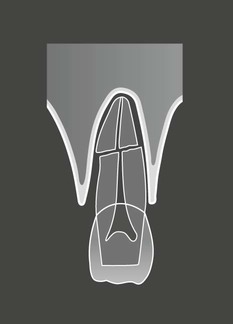
• A radiolucent line between the fragments
• An alteration in the outline shape of the root and discontinuity of the periodontal ligament shadow.
Examples of injured teeth and some of the more common post-injury complications evident radiographically are shown in Figs 29.2 and 29.3.
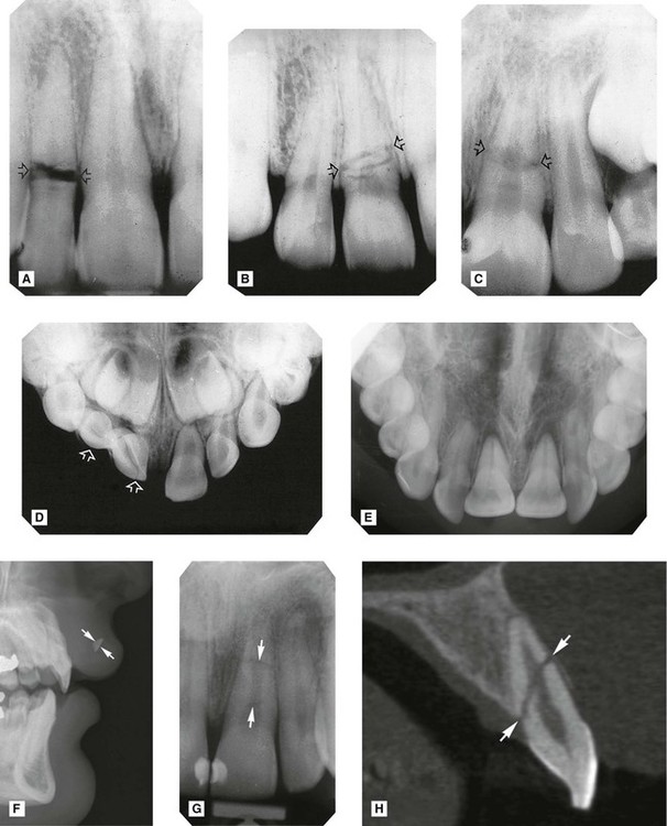
 (arrowed) with wide separation of the fragments. B Root fracture of
  (arrowed) with minimal separation of fragments. C Root fracture of
  (arrowed) with marked discontinuity in root outline. D Intrusion and fracture of
  (arrowed). E Palatal luxation of
  – crowns displaced palatally, roots displaced buccally – hence they appear foreshortened. Note also the widening of the periodontal ligament space. F Tooth fragment in the upper lip (arrowed). G Periapical and H Sagittal CBCT scan of a fractured
  (arrowed).
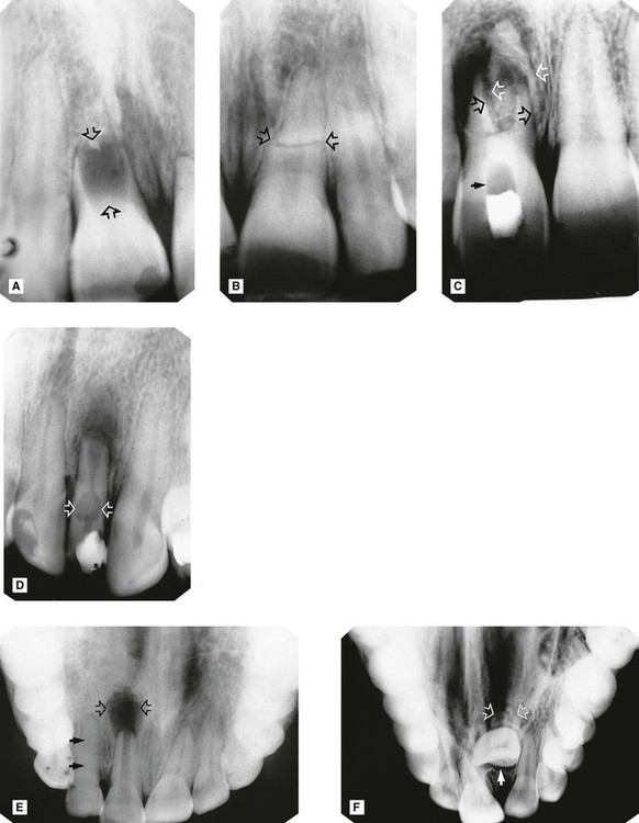
 at the time of injury (arrowed). B
  of the same patient showing a complete, but abnormally shaped, root with (root) fracture (arrowed). The periodontal ligament shadow is continuous. C Apical infection and resorption of
  resulting in separation and displacement of the root fragments (open arrows). A radiopaque calcium hydroxide dressing is evident in the root canal with a radiopaque temporary restoration in the crown. The radiolucent area in between contains cottonwool (solid arrow). D Apical infection, external resorption of the apex and extensive internal root resorption (arrowed) of
  , following a coronal fracture involving the pulp. A radiopaque temporary dressing is evident in the crown. E Large area of apical infection associated with
  (open arrows). Root formation of
  has ceased and the apex is immature. In addition, the
  (damaged but not killed by the original trauma) shows complete sclerosis of the pulp chamber (solid arrows). F Severe dilaceration and non-eruption of
  (arrowed), following trauma to the deciduous incisors several years previously.
Limitations of radiographic interpretation of fractured roots
As shown in Fig. 29.4 the radiographic appearances can be influenced by:
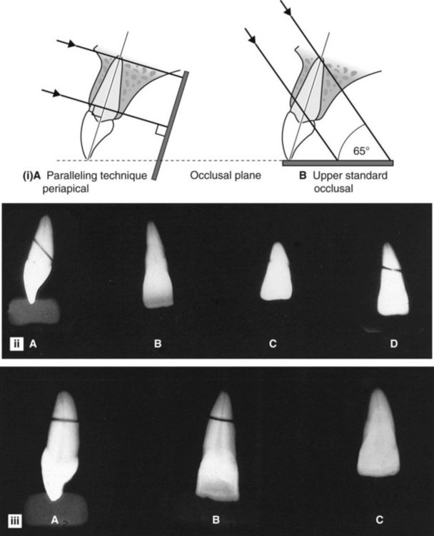
• The position and severity of the fracture
• The degree of displacement or separation of the fragments
• The position of the film and X-ray tubehead in relation to the fracture line(s).
It is for these reasons that a minimum of two views, from two different angles, is essential if small volume CBCT is not available.
Skeletal fractures
• The site and direction of the fracture line(s)
• The degree of displacement and separation of the bone ends
• The relationship of teeth to the fracture line
• The location of associated foreign bodies in hard and soft tissues
• The presence of coincidental or contributory disease
• The alignment of the bone fragments after treatment
• Healing and the identification of post-trauma complications including infection, non-union or malunion.
Fractures of the mandible
• Where the mandible tends to fracture
• Which radiographic views are required to show each of the fracture sites
• What radiological features indicate the presence of fracture(s)
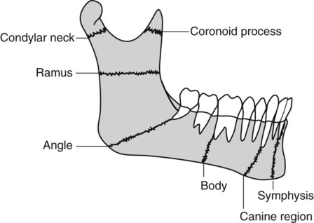
Radiographic projections required
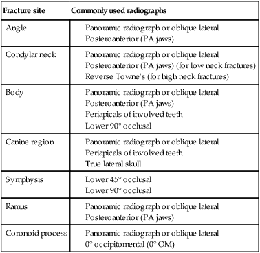
Several different views are used to show the various fracture sites. Once again, the ideal minimum requirement in all cases is two views at right angles to one another. When that is not possible, two views at two different angles should be used. In addition, intraoral views (either periapicals or occlusals) are required when fractures are in the tooth-bearing portion of the mandible and teeth are involved in the fracture line. The typical projections that can be used for the different sites are summarized in Table 29.1.
Table 29.1
| Fracture site | Commonly used radiographs |
| Angle |
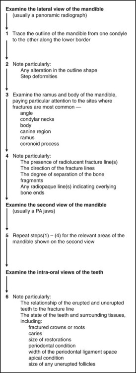
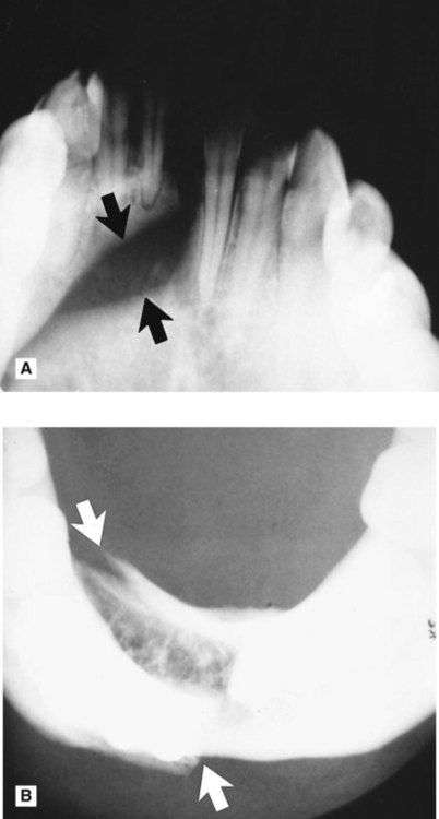
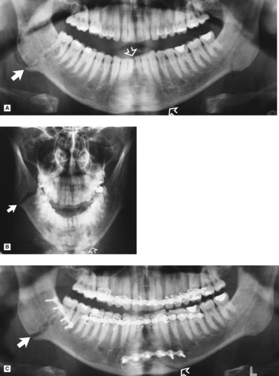
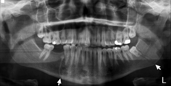
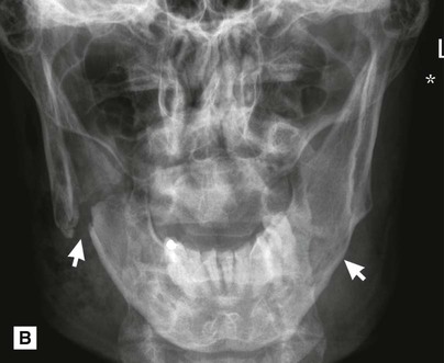
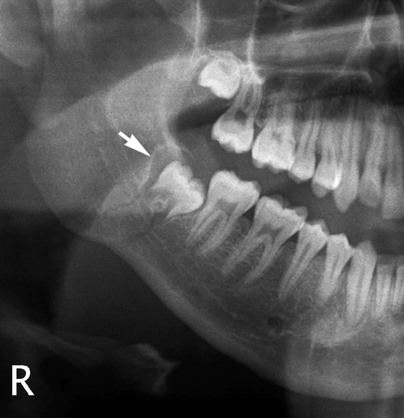
Radiological features of mandibular fractures (Fig. 29.6)
The typical radiographic appearances include:
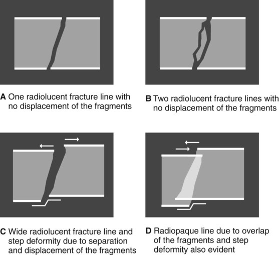
• Radiolucent line(s) between the bone fragments if they are separated. Note that fractures through the buccal and lingual cortical plates may produce two radiolucent lines
• A radiopaque line if the fragments overlie one another
• An alteration in the outline of the bone if the fragments are displaced, producing a step deformity of the lower border or the occlusal plane.
Important points to note
• The extent/severity of any displacement depends on:
– The direction and strength of the fracturing force
– The direction of the resultant fracture line
– The relevant muscles attached to each fragment and their direction of pull
• If the fracture line runs in such a manner that the associated muscles tend to hold the fragments together, the fracture is described as favourable
• If the associated muscles tend to pull the fragments apart, the fracture is described as unfavourable
• If the fracture involves a tooth socket there may be widening of the periodontal ligament space
• If the fracture involves an unerupted tooth the follicle may be enlarged.
Radiographic limitations
• The position and severity of the fracture
• The degree of displacement or separation of the fragments
• The position of the film and X-ray tubehead in relation to the fracture line(s), as shown in Fig. 29.7.
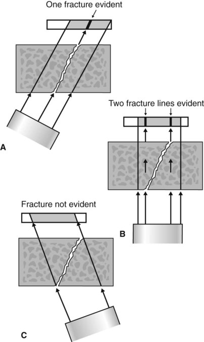
Important points to note
• It is because of these limitations that at least two views, at different angles, are required.
• If displacement and separation are minimal, there may be no radiographic evidence of a fracture at all.
• If available, CBCT using small or medium sized fields of view may be useful in fracture diagnosis if patient management will be affected.
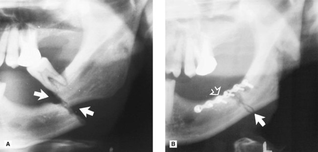
Interpretation of fractures
To emphasize, yet again, the importance of the principles outlined in Chapter 18, before any attempt is made to diagnose a fracture the quality of the radiographs should be assessed.
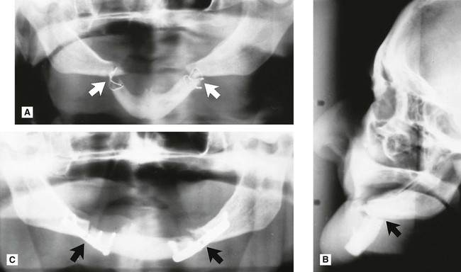
 . The fracture of the right body shows as a radiopaque line due to overlap of the fragments.
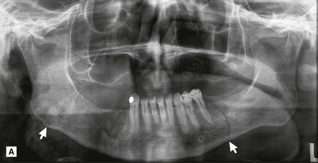
 (arrowed).
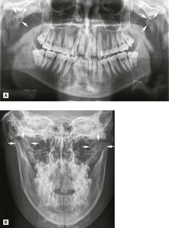
Fractures of the middle third of the facial skeleton
In addition, the knowledge required by the clinician can again be summarized as follows:
• Where the middle third of the face tends to fracture
• Which radiographic views are required to show each of the fracture sites
• What radiological features indicate the presence of fracture(s)
Classification and the main fracture sites
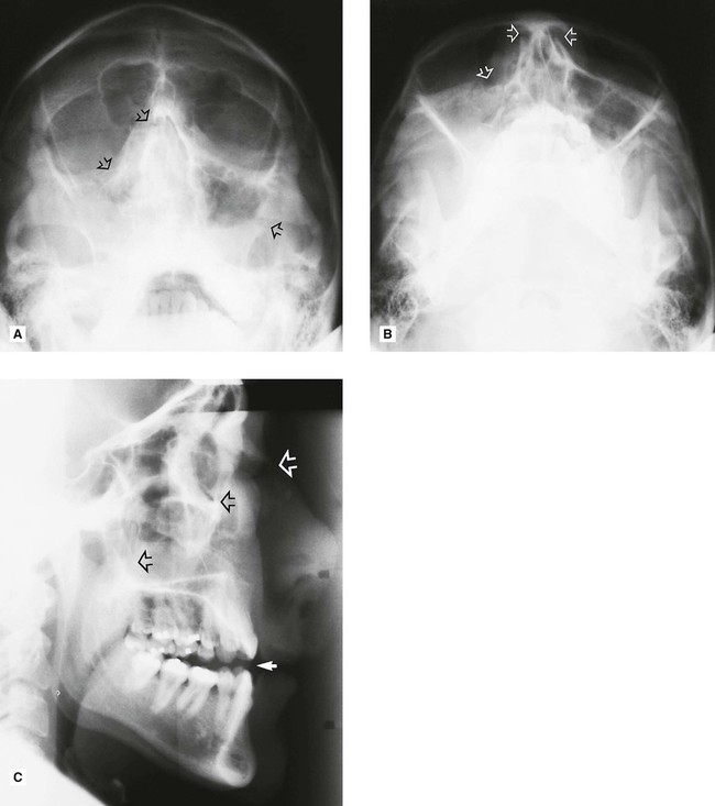
Most injuries to the middle third of the face are from the front, forcing part or parts of the facial skeleton downwards and backwards along the cranial base. The resulting lines of fracture follow the lines of weakness of the facial skeleton, as shown in Fig. 29.18. This allows a broad classification based on site, as follows:
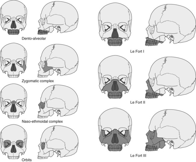
• Central middle third fractures, including:
– Le Fort’s type I, bilateral detachment of the alveolar process and palate, or the low-level subzygomatic fracture of Guérin
– Le Fort’s type II, pyramidal, subzygomatic fracture of the maxilla
– Le Fort’s type III, high-level suprazygomatic fracture of the central and lateral parts of the face
• Fractures of the zygomatic complex, including:
Radiographic investigation
Important points to note
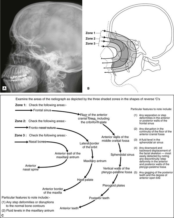
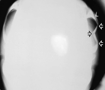
• In a casualty department, the patient is usually X-rayed lying down as shown in Chapter 13. The true lateral projection should be taken with the patient supine (brow up), and with the X-ray beam horizontal, to show the possible fluid level. This projection is therefore sometimes referred to as a brow-up lateral or shoot-through lateral (see Fig. 13.1A).
• The projections that can be used for the different fracture sites are summarized in Table 29.2. Again the principle of requiring a minimum of two views at right angles applies but, as indicated, several views may be necessary.
Table 29.2
Summary of the common radiographic projections used to show the various middle third fracture sites
| Fracture type/site | Commonly used investigations |
| Dento-alveolar |
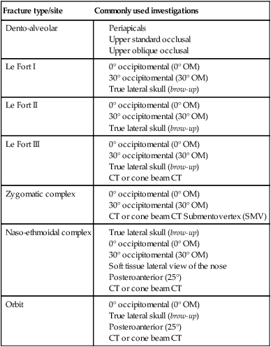
• A useful tip to remember is that the occipitomental radiographs should be viewed initially from a distance of about a metre to allow an easy comparison of both sides and to detect any facial asymmetry.
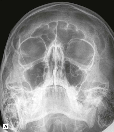
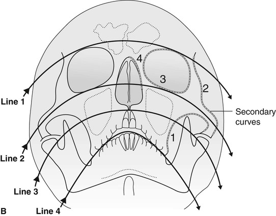
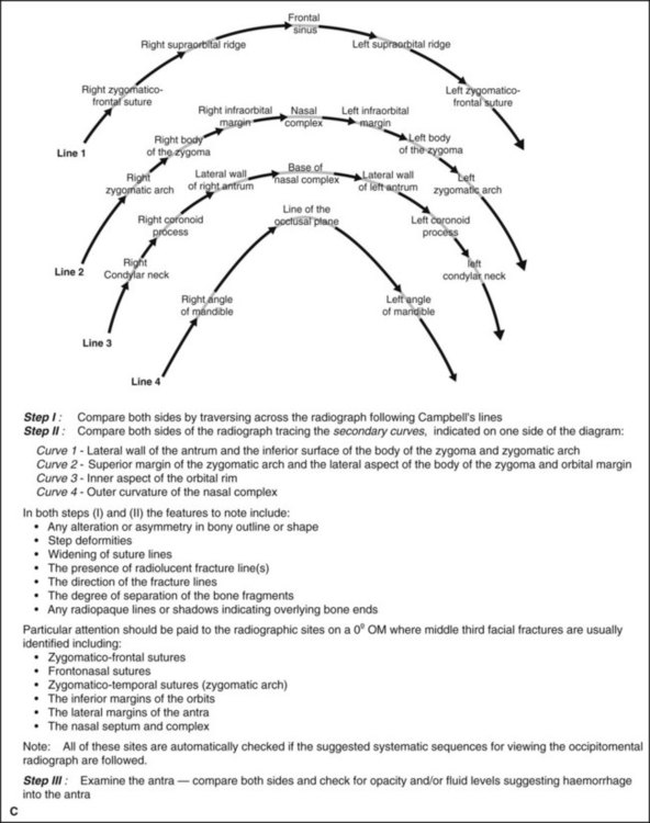
Interpretation of middle third fractures
Systematic approach
• Examine the 0° OM using an approach based broadly on that suggested originally by McGrigor and Campbell (1950), often referred to as Campbell’s lines (Fig. 29.19).
 />
/> />
/>
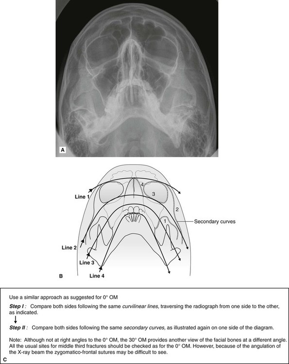
• Examine the 30° OM as shown in Fig. 29.20.
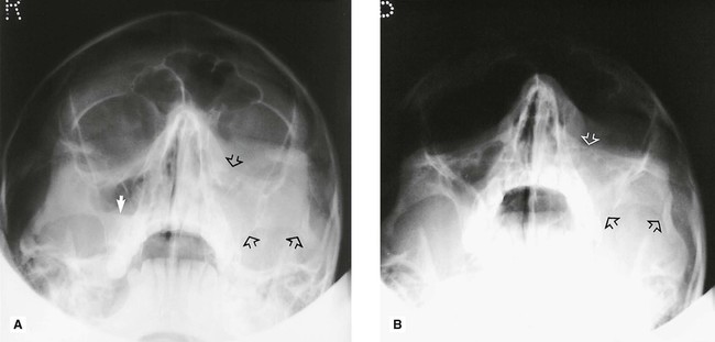
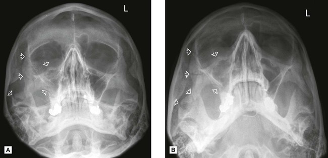
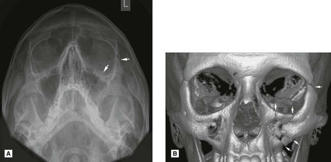
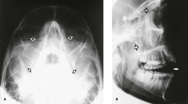
Examples of middle third facial fractures
Examples of injuries to different parts of the facial skeleton are shown in Figs 29.22–29.29.
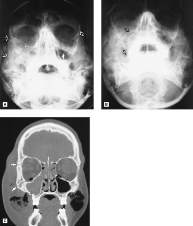
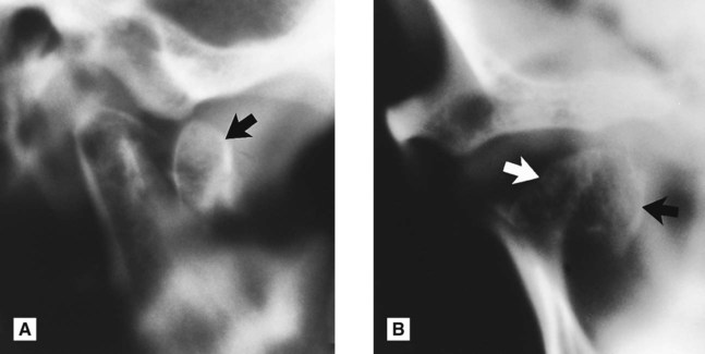
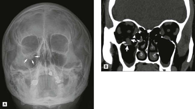
Orbital blow-out fracture
Following a direct blow to the globe of the eye, the orbital rim remains intact but the force of the blow is transmitted either downwards or medially. The very thin bones of the orbital floor can break and allow the contents of the globe to herniate downwards into the antrum. Superimposition on conventional radiographs makes this type of fracture difficult to detect, hence the need for CT (if available) or cone beam CT to determine the site and severity of the injury (see Fig. 29.30).
Other fractures and injuries
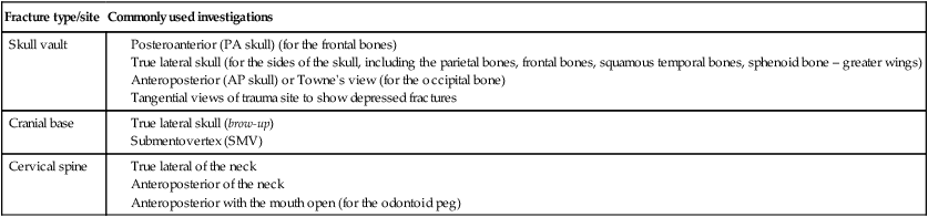
It is beyond the scope of this book to discuss these injuries in detail, but the more commonly used radiographic investigations of the cranium and cervical spine are summarized in Table 29.3.
Table 29.3
| Fracture type/site | Commonly used investigations |
| Skull vault |
To access the self assessment questions for this chapter please go to www.whaitesessentialsdentalradiography.com
[/level-membership-for-radiology-category][not-level-membership-for-radiology-category]
Trauma to the teeth and facial skeleton
Injuries to the teeth and their supporting structures
Types of injury
Other injuries
• Displacement of an underlying developing tooth which may become dilacerated as a result
• Soft tissue injuries, such as:
Radiographic investigation
• Two views of the injured tooth from different angles, ideally at right angles to one another, but more usually with the X-ray tubehead in two different positions in the vertical plane.
• Small volume CBCT (if available) providing coronal, sagittal and axial images.
• Reproducible views to provide a base-line assessment and to allow subsequent follow-up evaluation
• Views of the chest and/or abdomen if a tooth or foreign body is thought to have been inhaled or swallowed, including:
Diagnostic information provided
The diagnostic information provided by these radiographs may include:
• The type of injury to the teeth
• The degree of displacement of the tooth fragments
• The stage of root development
• The condition of the apical tissues
• The presence, site and displacement of alveolar bone fractures
• The condition of adjacent or underlying teeth
Radiographic interpretation
The expected radiographic features indicating a fractured root are shown in Fig. 29.1 and include:
• A radiolucent line between the fragments
• An alteration in the outline shape of the root and discontinuity of the periodontal ligament shadow.
Examples of injured teeth and some of the more common post-injury complications evident radiographically are shown in Figs 29.2 and 29.3.
Limitations of radiographic interpretation of fractured roots
As shown in Fig. 29.4 the radiographic appearances can be influenced by:
• The position and severity of the fracture
• The degree of displacement or separation of the fragments
• The position of the film and X-ray tubehead in relation to the fracture line(s).
It is for these reasons that a minimum of two views, from two different angles, is essential if small volume CBCT is not available.
Skeletal fractures
• The site and direction of the fracture line(s)
• The degree of displacement and separation of the bone ends
• The relationship of teeth to the fracture line
• The location of associated foreign bodies in hard and soft tissues
• The presence of coincidental or contributory disease
• The alignment of the bone fragments after treatment
• Healing and the identification of post-trauma complications including infection, non-union or malunion.
