[level-membership-for-radiology-category]
Tomography and panoramic radiography
Introduction
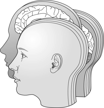
Conventional tomography is a specialized radiographic technique developed originally for producing radiographs that showed only a section or slice of a patient. A useful analogy is to regard the technique as one that enables the patient to be imaged in slices – like a loaf of sliced bread (see Fig. 15.1). Each individual tomographic image (or slice) shows the tissues within that section sharply defined and in focus. The section is thus referred to as the focal plane or focal trough. Tissues and structures outside the tomographic section are not visible because they are very blurred and out of focus.
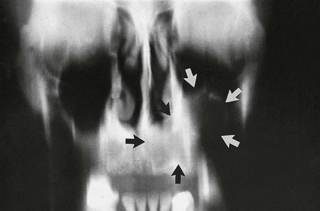
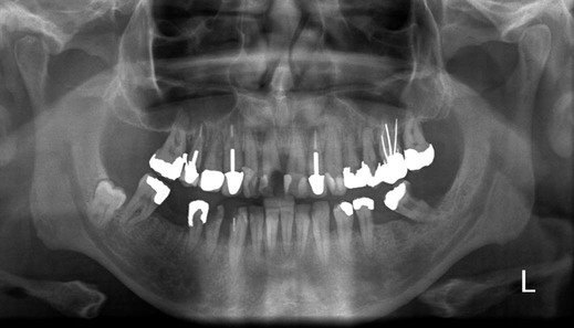
Production of each conventional tomographic slice required controlled, accurate movement of both the X-ray tubehead and the film during the exposure, thereby making it different from all the routine radiographic techniques described in previous chapters. As will be described later in this chapter, by varying the size of the X-ray beam and the type of equipment movement employed it proved possible to change the shape of the tomographic layer from a straight (linear) line (see Fig. 15.2) to a curve, and ultimately to the approximate horseshoe shape of the dental arch, providing an overall panoramic image of all the teeth and their supporting structures – the so-called dental panoramic tomograph (DPT) or panoramic radiograph (see Fig. 15.3).
While panoramic tomography remains very popular, conventional linear tomography has essentially been superseded in radiography by computed tomography, which enables computer-generated tomographic sectional images to be created. Cone beam computed tomography (CBCT) is described in Chapter 16 and medical computed tomography (CT) is described in Chapter 18. The concept of tomographic slices or sectional images also forms the basis of many other modern imaging modalities, such as magnetic resonance (MR) imaging and ultrasound, which are also described in Chapter 18.
Tomographic theory
• Linear tomography using a wide or broad X-ray beam
• Linear tomography using a narrow or slit X-ray beam
• Rotational curved tomography using a narrow slit X-ray beam.
Principle of tomographic movement
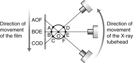
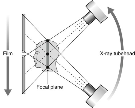
As stated, tomography requires controlled, accurate movement of both the X-ray tubehead and the film. They are therefore linked together. During the exposure, the X-ray tubehead moves in one direction while the film moves in the opposite direction, as shown in Fig. 15.4. The point at the centre of this rotating movement will appear in focus on the resultant radiograph, since its shadow will appear in the same place on the film throughout the exposure. All other points will appear blurred or out of focus.
Broad-beam linear tomography
The principle of tomography illustrated in Fig. 15.4 shows a very thin X-ray beam producing one point (O) – the centre of rotation – in focus on the film. To produce a section or slice of the patient in focus, a broad X-ray beam is used. For each part of the beam, there is a separate centre of rotation, all of which lie in the same focal plane. The resultant tomography will therefore show all these points sharply defined. The principle of broad-beam tomography is illustrated in Fig. 15.5.
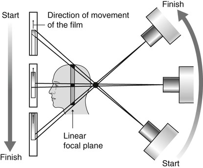
Slit or narrow-beam linear tomography
• The X-ray beam has to be collimated from a broad beam to a narrow beam.
• The film cassette has to be placed behind a protective metal shield. A narrow opening in this shield is required to allow a small part of the film to be exposed to the X-ray beam at any one instant.
• A cassette carrier, incorporating the metal shield, has to be linked to the X-ray tubehead to ensure that they move in the opposite direction to one another during the exposure. This produces the synchronized tomographic movement in the vertical plane.
• Within this carrier, the film cassette itself has to be moved in the same direction as the tubehead. This ensures that a different part of the film is exposed to the X-ray beam throughout the exposure.
The principle of narrow-beam linear tomography using this equipment is illustrated in Fig. 15.6.
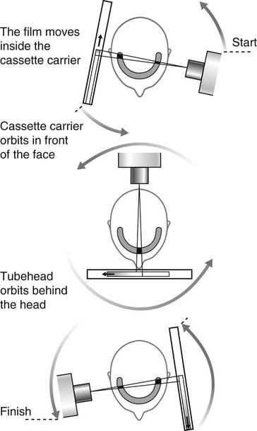
Narrow-beam rotational tomography
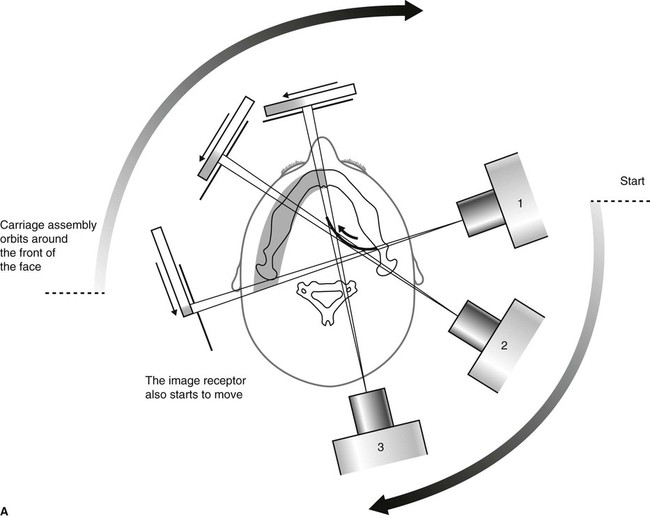
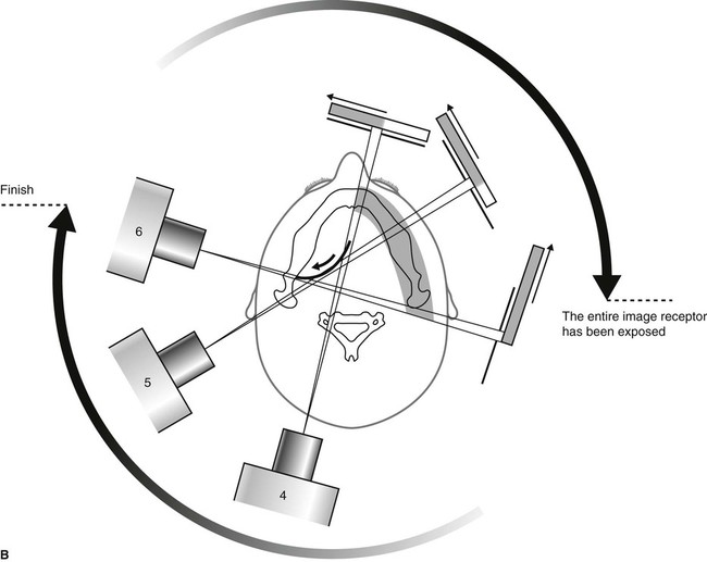
In this type of tomography, narrow-beam equipment is again used, but the synchronized movement of the X-ray tubehead and the cassette carrier are designed to rotate in the horizontal plane, in a circular path around the head, with a single centre of rotation. The resultant focal trough is curved and forms the arc of a circle, as shown in Fig. 15.7.
Important points to note
• The X-ray tubehead orbits around the back of the head while the cassette carrier with the film orbits around the front of the face.
• The X-ray tubehead and the cassette carrier appear to move in opposite directions to one another.
• The film moves in the same direction as the X-ray tubehead, behind the protective metal shield of the cassette carrier.
• A different part of the film is exposed to the X-ray beam at any one instant, as the equipment orbits the head.
• The simple circular rotational movement with a single centre of rotation produces a curved circular focal trough.
• As in conventional tomography, shadows of structures not within the focal trough will be out of focus and blurred owing to the tomographic movement.
Panoramic tomography
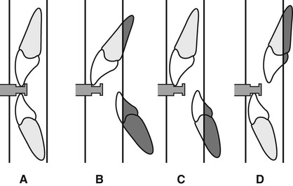
There are several dental panoramic units available; they all work on the same principle but differ in how the rotational movement is modified to image the elliptical dental arch. Four main methods (see Fig. 15.8) have been used including:
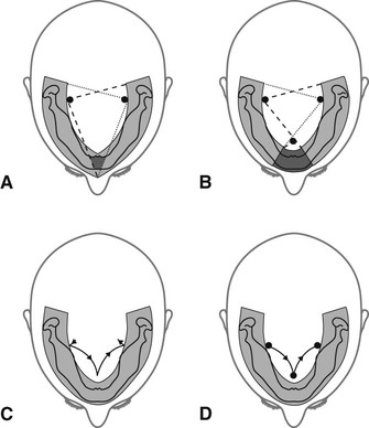
• Two stationary centres of rotation, using two separate circular arcs
• Three stationary centres of rotation, using three separate circular arcs
• A continually moving centre of rotation using multiple circular arcs combined to form a final elliptical shape
• A combination of three stationary centres of rotation and a moving centre of rotation.
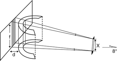
However, the focal troughs are produced, it should be remembered that they are three-dimensional. The focal trough is thus sometimes described as a focal corridor. All structures within the corridor, including the mandibular and maxillary teeth, will be in focus on the final radiograph. The vertical height of the corridor is determined by the shape and height of the X-ray beam and the size of the film, as shown in Fig. 15.9.
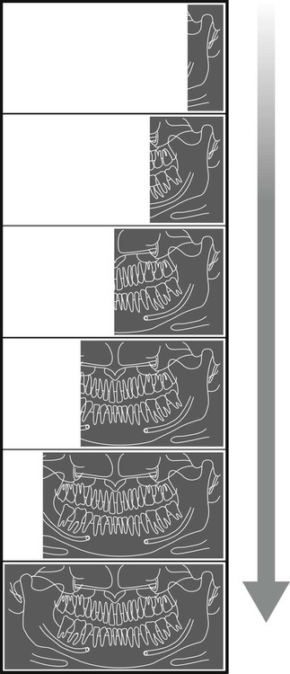
As in other forms of narrow-beam tomography, a different part of the focal trough is imaged throughout the exposure. The final radiograph is thus built up of sections (see Fig. 15.10), each created separately, as the equipment orbits around the patient’s head.
Selection criteria
• Where a bony lesion or unerupted tooth is of a size or position that precludes its complete demonstration on intraoral radiographs
• In the case of a grossly neglected mouth
• As part of an assessment of periodontal bone support often supplemented with periapical radiographs
• For the assessment of wisdom teeth prior to planned surgical intervention. Routine radiography of unerupted third molars is not recommended
• As part of an orthodontic assessment where there is a clinical need to know the state of the dentition and the presence/absence of teeth. The use of clinical criteria to select patients rather than routine screening patients is essential.
In addition, in dental hospitals panoramic radiographs are also used to assess:
• Fractures of all parts of the mandible except the anterior region
• Antral disease — particularly to the floor, posterior and medial walls of the antra
• Destructive diseases of the articular surfaces of the TMJ
• Vertical alveolar bone height and position of anatomical structures as part of pre-implant planning.
Equipment
• An X-ray tubehead, producing a narrow fan-shaped X-ray beam, angled upwards at approximately 8° to the horizontal (see Fig. 15.9)
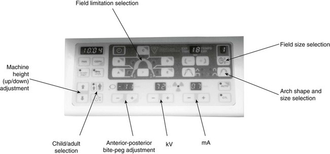
• Control panel (see Fig. 15.11)
• Patient-positioning apparatus, including chin and appropriate head immobilizing supports and light beam markers
• An image receptor (film or digital), with or without an associated carriage assembly.
Traditional panoramic equipment was designed to use indirect-action radiographic film in an extraoral cassette as the image receptor. With the advent of digital imaging several variations in image receptor now exist, including:
• Cassettes containing indirect-action film and rare-earth intensifying screens
• Cassettes containing a digital phosphor plate
• Flat cassette-sized solid-state sensors designed to fit into existing equipment
• Specially designed solid-state sensors — an integral part of new equipment (see Ch. 6).
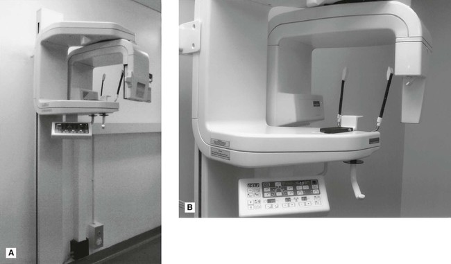
Examples of two typical machines are shown in Fig. 15.12. Ideally:
• Equipment should have a range of tube potential settings, preferably 60–90 kV.
• The beam height at the receiving slit of the cassette holder should not be greater than the film in use (normally 125 mm or 150 mm). The width of the beam should not be greater than 5 mm.
• Equipment should be provided with adequate patient-positioning aids incorporating light beam markers.
• Equipment should provide facilities for field-limitation techniques.
Technique and positioning
Equipment preparation
• The cassette containing the film or phosphor plate should be inserted into carriage assembly (if appropriate).
• The operator should put on suitable protective gloves (e.g. latex or nitrile) (see Ch. 8).
• The collimation should be set to the size of field required.
• The appropriate exposure factors should be selected according to the size of the patient — typically in range 70–90 kV and 4–12 mA.
Patient positioning
• The patient should be positioned in the unit so that their spine is straight and instructed to hold any stabilizing supports or handles provided (see Fig. 15.14).
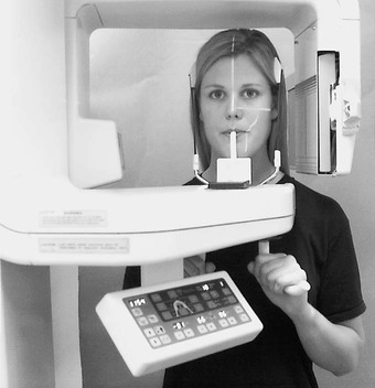
• The patient should be instructed to bite their upper and lower incisors edge-to-edge on the bite-peg with their chin in good contact with the chin support.
• The head should be immobilized using the temple supports.
• The light beam markers should be used so that the mid-sagittal plane is vertical, the Frankfort plane is horizontal and the canine light lies between the upper lateral incisor and canine.
• The patient should be instructed to close their lips and press their tongue on the roof of their mouth so that it is in contact with their hard palate and not to move throughout the exposure cycle (approximately 15–18 seconds).
Important points to note
• Panoramic radiography is generally considered to be unsuitable for children under six years old, because of the length of the exposure and the need for the patient to keep still.
• A protective lead apron should not be used. In the UK the 2001 Guidance Notes confirm that there is no justification for using a protective lead apron. If used, it can interfere with the final image (see Fig. 15.27H).
The importance of accurate patient positioning
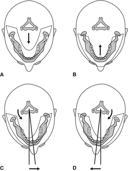
The positioning of the patient’s head within this type of equipment is critical — it must be positioned accurately so that the teeth lie within the focal trough. The effects of placing the head too far forward, too far back or asymmetrically in relation to the focal trough are shown in Fig. 15.15. The parts of the jaws outside the focal trough will be out of focus. The fan-shaped X-ray beam causes patient malposition to be represented mainly as distortion in the horizontal plane, i.e. teeth appear too wide or too narrow rather than foreshortened or elongated. Thus, if the patient is rotated to the left (as shown in Fig. 15.15C), the left teeth are nearer the film and will be narrower, while the teeth on the right will be further away from the film and wider. These and other positioning errors are shown later (see Fig. 15.28).
However accurately the patient’s head is positioned, the inclination of the incisor teeth, or the underlying skeletal base pattern, may make it impossible to position both the mandibular and maxillary teeth ideally within the focal corridor (see Fig. 15.16).
Technique variations
There are a number of technique variations possible with modern equipment, including:
• Edentulous patient positioning — the chin support is used instead of the bite-peg and the canine positioning light beam is centred on the corner of the mouth.
• TMJ programmes — (see Ch. 30).
• Cross-sectional imaging for implant assessment.
• Collimation — (see Ch. 23) restricting the size of the beam so restricting the field of view, e.g. the height of the beam is automatically reduced when selecting the settings for children.
• Field limitation techniques — only preselected parts of the patient are exposed and imaged on the final film as illustrated in Fig. 15.17.
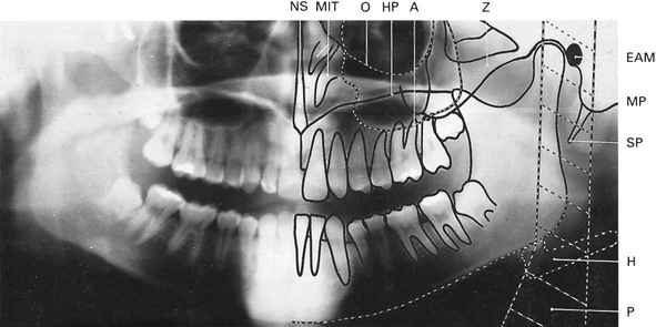
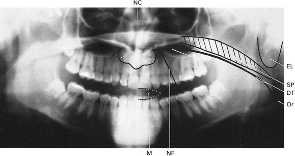
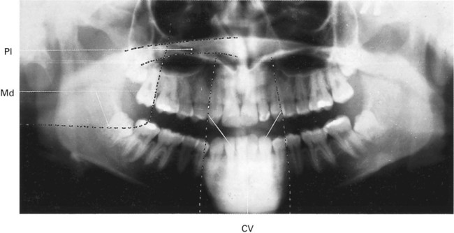
Normal anatomy
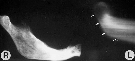
• Real or actual shadows of structures in, or close to, the focal trough
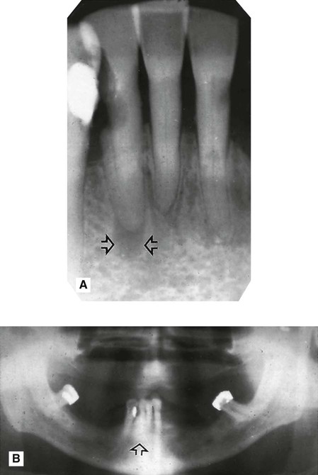
• Ghost or artefactual shadows created by the tomographic movement and cast by structures on the opposite side or a long way from the focal trough. The 8° upward angulation of the X-ray beam means that these ghost shadows appear at a higher level than the structures that have caused them as shown in Figs 15.18 and 15.19.
Advantages and disadvantages
Advantages
• A large area is imaged and all the tissues within the focal trough are displayed, including the anterior teeth, even when the patient is unable to open the mouth.
• The image is easy for patients to understand, and is therefore a useful teaching aid.
• Patient movement in the vertical plane distorts only that part of the image being produced at that instant.
• Positioning is relatively simple and minimal expertise is required.
• The overall view of the jaws allows rapid assessment of any underlying, possibly unsuspected, disease.
• The view of both sides of the mandible on one film is useful when assessing fractures and is comfortable for the injured patient.
• The overall view is useful for evaluation of periodontal status and in orthodontic assessments.
• The antral floor, medial and posterior walls are well shown.
• Both condylar heads are shown on one film, allowing easy comparison (see Ch. 30).
• The radiation dose (effective dose) may be lower than a full mouth survey of intraoral images in some cases (see Ch. 6).
• Development of field limitation techniques which result in further dose reduction.
Disadvantages
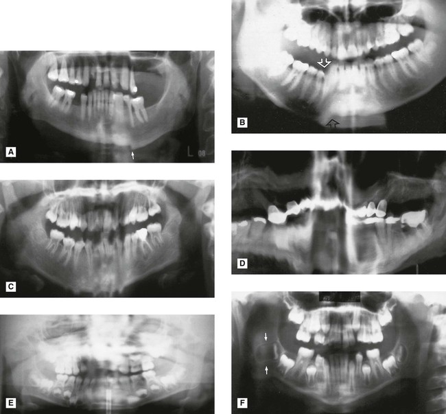
• The tomographic image represents only a section of the patient. Structures or abnormalities not in the focal trough may not be evident (Fig. 15.23).
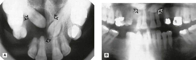
 and a large dentigerous cyst (arrowed) associated with
  B Panoramic radiograph showing the two unerupted canines out of focus (arrowed) and only a suggestion of the dentigerous cyst, because they are all outside the focal trough.
• Soft tissue and air shadows can overlie the required hard tissue structures (Fig. 15.24).
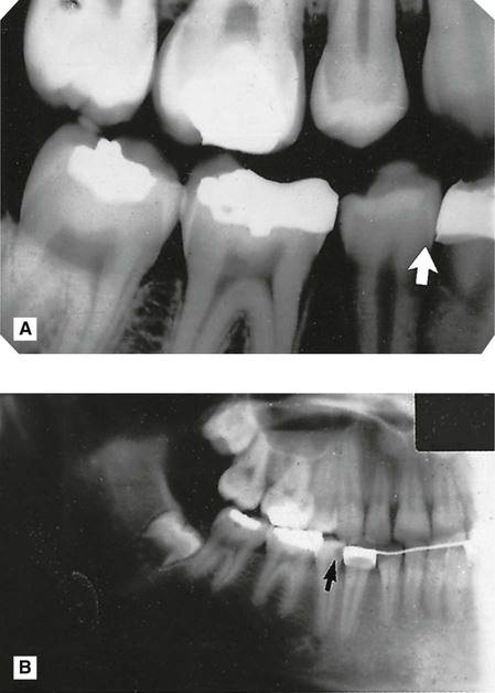
 (arrowed). B Panoramic radiograph showing an apparent lesion in this tooth (arrowed). This appearance is created by the overlying air shadow of the corner of the mouth.
• Ghost or artefactual shadows can overlie the structures in the focal trough (Fig. 15.25).
 region showing an area of radiolucency at the apex of
  (arrowed). B Panoramic radiograph showing no evidence of the lesion (arrowed) owing to superimposition of the shadow of the cervical vertebrae.
• The tomographic movement together with the distance between the focal trough and image receptor produce distortion and magnification of the final image (approx. × 1.3).
• The use of indirect-action film and intensifying screens results in some loss of image quality but image resolution can be improved by using digital image receptors.
• The technique is not suitable for children under six years or on some disabled patients because of the length of the exposure cycle.
• Some patients do not conform to the shape of the focal trough and some structures will be out of focus.
• Movement of the patient during the exposure can create difficulties in image interpretation (Fig. 15.26).
Assessment of image quality
• Comparison of the image against ideal quality criteria
• Subjective rating of image quality using published standards
• Detailed assessment of rejected films to determine the source of error.
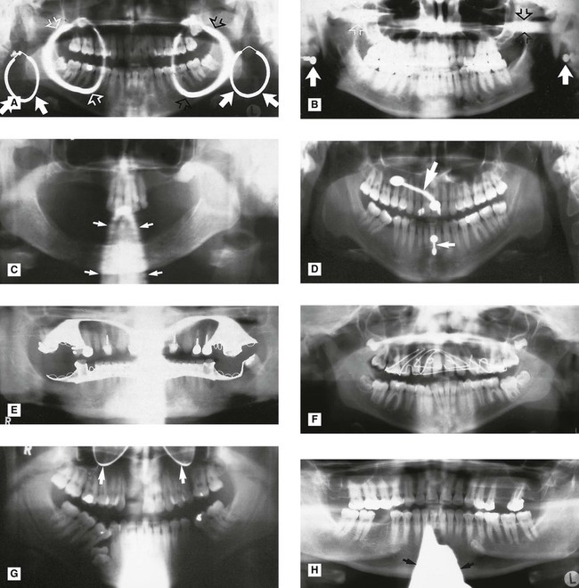
Ideal quality criteria
• All the upper and lower teeth and their supporting alveolar bone should be clearly demonstrated.
• The whole of the mandible should be included.
• Magnification in the vertical and horizontal planes should be equal.
• The right and left molar teeth should be equal in their mesiodistal dimension.
• The density across the image should be uniform with no air shadow above the tongue creating a radiolucent (black) band over the roots of the upper teeth.
• The image of the hard palate should appear above the apices of the upper teeth.
• Only the slightest ghost shadows of the contralateral angle of the mandible and the cervical spine should be evident.
• There should be no evidence of artefactual shadows due to dentures, earrings and other jewellery.
• The patient identification label should not obscure any of the above features.
• The image should be clearly labelled with the patient’s name and date of the examination.
• The image should be clearly marked with a Right and/or Left letter.
Subjective rating of image quality
The simple three-point subjective rating scale published in the UK’s 2001 Guidance Notes was introduced in Chapter 9 and is discussed in detail, together with the errors associated with exposure factors and chemical processing, in Chapter 17. The summary is shown again in Table 15.1. Panoramic patient preparation and positioning errors are described below.
Table 15.1
| Rating | Quality | Basis |
| 1 | Excellent | No errors of patient preparation, exposure, positioning, processing or film handling |
| 2 | Diagnostically acceptable | Some errors of patient preparation, exposure, positioning, processing or film handling, but which do not detract from the diagnostic utility of the radiograph |
| 3 | Unacceptable | Errors of patient preparation, exposure, positioning, processing or film handling, which render the radiograph diagnostically unacceptable |
Assessment of rejected films and determination of errors
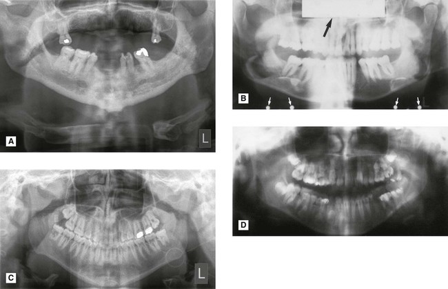
Patient positioning errors (Figs 15.28 and 15.29)
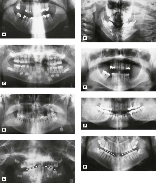
 region (arrowed). C Multiple vertical movements while the anterior teeth were being imaged. D Continuous shaking movements throughout the cycle. E Sudden side-to-side horizontal movement while the anterior teeth were being imaged causing them to be blurred. F Horizontal movement towards the end of the cycle causing horizontal elongation and stretching of the shadow of the developing lower right third molar (arrowed).
• Failure to ensure that the spine is straight (ghosting shadow error)
• Failure to ensure the incisors are biting edge-to-edge on the bite-peg (anteroposterior error)
• Failure to use the light beam marker to ensure midsagittal plane is vertical and the head is not rotated (horizontal error)
• Failure to use the light beam marker to ensure the Frankfort plane is horizontal (vertical error)
• Failure to instruct the patient to press the tongue against the roof of the mouth (air shadow error)
• Failure to instruct the patient to remain still throughout the exposure (movement error).
Footnote
Panoramic radiographs should not be considered an alternative to high-resolution intraoral radiographs. However, they are commonly considered as an alternative to right and left oblique lateral radiographs or the bimolar projection (see Ch. 12) mainly because it is assumed that less operator expertise is required to produce panoramic images of adequate diagnostic quality. Unfortunately, the multiple and varied causes of error in panoramic radiography make the technique very operator-dependent, no matter how sophisticated the equipment and the image receptors become. The use of digital sensors (solid-state or phosphor plate) improves the resolution of panoramic images when compared to those captured using indirect-action film and intensifying screen combinations. In addition, digital images can be enhanced and manipulated using computer software (see Ch. 5).
The diagnostic value of all panoramic images is increased considerably if clinicians understand that the image created is a tomograph (whatever the image receptor) and are aware of the limitations that this imposes. A suggested systematic approach to interpretation of panoramic images is outlined in Chapter 19.
To access the self assessment questions for this chapter please go to www.whaitesessentialsdentalradiography.com
[/level-membership-for-radiology-category][not-level-membership-for-radiology-category]
Tomography and panoramic radiography
Introduction
Conventional tomography is a specialized radiographic technique developed originally for producing radiographs that showed only a section or slice of a patient. A useful analogy is to regard the technique as one that enables the patient to be imaged in slices – like a loaf of sliced bread (see Fig. 15.1). Each individual tomographic image (or slice) shows the tissues within that section sharply defined and in focus. The section is thus referred to as the focal plane or focal trough. Tissues and structures outside the tomographic section are not visible because they are very blurred and out of focus.
Production of each conventional tomographic slice required controlled, accurate movement of both the X-ray tubehead and the film during the exposure, thereby making it different from all the routine radiographic techniques described in previous chapters. As will be described later in this chapter, by varying the size of the X-ray beam and the type of equipment movement employed it proved possible to change the shape of the tomographic layer from a straight (linear) line (see Fig. 15.2) to a curve, and ultimately to the approximate horseshoe shape of the dental arch, providing an overall panoramic image of all the teeth and their supporting structures – the so-called dental panoramic tomograph (DPT) or panoramic radiograph (see Fig. 15.3).
While panoramic tomography remains very popular, conventional linear tomography has essentially been superseded in radiography by computed tomography, which enables computer-generated tomographic sectional images to be created. Cone beam computed tomography (CBCT) is described in Chapter 16 and medical computed tomography (CT) is described in Chapter 18. The concept of tomographic slices or sectional images also forms the basis of many other modern imaging modalities, such as magnetic resonance (MR) imaging and ultrasound, which are also described in Chapter 18.
Tomographic theory
• Linear tomography using a wide or broad X-ray beam
• Linear tomography using a narrow or slit X-ray beam
• Rotational curved tomography using a narrow slit X-ray beam.
Principle of tomographic movement
As stated, tomography requires controlled, accurate movement of both the X-ray tubehead and the film. They are therefore linked together. During the exposure, the X-ray tubehead moves in one direction while the film moves in the opposite direction, as shown in Fig. 15.4. The point at the centre of this rotating movement will appear in focus on the resultant radiograph, since its shadow will appear in the same place on the film throughout the exposure. All other points will appear blurred or out of focus.
Broad-beam linear tomography
The principle of tomography illustrated in Fig. 15.4 shows a very thin X-ray beam producing one point (O) – the centre of rotation – in focus on the film. To produce a section or slice of the patient in focus, a broad X-ray beam is used. For each part of the beam, there is a separate centre of rotation, all of which lie in the same focal plane. The resultant tomography will therefore show all these points sharply defined. The principle of broad-beam tomography is illustrated in Fig. 15.5.
Slit or narrow-beam linear tomography
• The X-ray beam has to be collimated from a broad beam to a narrow beam.
• The film cassette has to be placed behind a protective metal shield. A narrow opening in this shield is required to allow a small part of the film to be exposed to the X-ray beam at any one instant.
• A cassette carrier, incorporating the metal shield, has to be linked to the X-ray tubehead to ensure that they move in the opposite direction to one another during the exposure. This produces the synchronized tomographic movement in the vertical plane.
• Within this carrier, the film cassette itself has to be moved in the same direction as the tubehead. This ensures that a different part of the film is exposed to the X-ray beam throughout the exposure.
The principle of narrow-beam linear tomography using this equipment is illustrated in Fig. 15.6.
Narrow-beam rotational tomography
In this type of tomography, narrow-beam equipment is again used, but the synchronized movement of the X-ray tubehead and the cassette carrier are designed to rotate in the horizontal plane, in a circular path around the head, with a single centre of rotation. The resultant focal trough is curved and forms the arc of a circle, as shown in Fig. 15.7.
Important points to note
• The X-ray tubehead orbits around the back of the head while the cassette carrier with the film orbits around the front of the face.
• The X-ray tubehead and the cassette carrier appear to move in opposite directions to one another.
• The film moves in the same direction as the X-ray tubehead, behind the protective metal shield of the cassette carrier.
• A different part of the film is exposed to the X-ray beam at any one instant, as the equipment orbits the head.
• The simple circular rotational movement with a single centre of rotation produces a curved circular focal trough.
• As in conventional tomography, shadows of structures not within the focal trough will be out of focus and blurred owing to the tomographic movement.
Panoramic tomography
There are several dental panoramic units available; they all work on the same principle but differ in how the rotational movement is modified to image the elliptical dental arch. Four main methods (see Fig. 15.8) have been used including:
• Two stationary centres of rotation, using two separate circular arcs
• Three stationary centres of rotation, using three separate circular arcs
• A continually moving centre of rotation using multiple circular arcs combined to form a final elliptical shape
• A combination of three stationary centres of rotation and a moving centre of rotation.
However, the focal troughs are produced, it should be remembered that they are three-dimensional. The focal trough is thus sometimes described as a focal corridor. All structures within the corridor, including the mandibular and maxillary teeth, will be in focus on the final radiograph. The vertical height of the corridor is determined by the shape and height of the X-ray beam and the size of the film, as shown in Fig. 15.9.
As in other forms of narrow-beam tomography, a different part of the focal trough is imaged throughout the exposure. The final radiograph is thus built up of sections (see Fig. 15.10), each created separately, as the equipment orbits around the patient’s head.
Selection criteria
• Where a bony lesion or unerupted tooth is of a size or position that precludes its complete demonstration on intraoral radiographs
• In the case of a grossly neglected mouth
• As part of an assessment of periodontal bone support often supplemented with periapical radiographs
• For the assessment of wisdom teeth prior to planned surgical intervention. Routine radiography of unerupted third molars is not recommended
• As part of an orthodontic assessment where there is a clinical need to know the state of the dentition and the presence/absence of teeth. The use of clinical criteria to select patients rather than routine screening patients is essential.
In addition, in dental hospitals panoramic radiographs are also used to assess:
• Fractures of all parts of the mandible except the anterior region
• Antral disease — particularly to the floor, posterior and medial walls of the antra
• Destructive diseases of the articular surfaces of the TMJ
• Vertical alveolar bone height and position of anatomical structures as part of pre-implant planning.
Equipment
• An X-ray tubehead, producing a narrow fan-shaped X-ray beam, angled upwards at approximately 8° to the horizontal (see Fig. 15.9)
• Control panel (see Fig. 15.11)
• Patient-positioning apparatus, including chin and appropriate head immobilizing supports and light beam markers
• An image receptor (film or digital), with or without an associated carriage assembly.
Traditional panoramic equipment was designed to use indirect-action radiographic film in an extraoral cassette as the image receptor. With the advent of digital imaging several variations in image receptor now exist, including:
• Cassettes containing indirect-action film and rare-earth intensifying screens
• Cassettes containing a digital phosphor plate
• Flat cassette-sized solid-state sensors designed to fit into existing equipment
• Specially designed solid-state sensors — an integral part of new equipment (see Ch. 6).
[/not-level-membership-for-radiology-category]
