28 Timing Cycles of Implantable Devices
To better understand device behaviors and to optimize management of patients with implantable pacemakers, physicians must be familiar with the timing cycles and their constant interactions with the patient’s intrinsic rhythm.1 Timing cycles refer to the beat-by-beat behavior of implantable cardiac electronic devices (CIEDs) in response to changes in intrinsic and paced behavior. Some parameters involved in timing cycles are programmable, whereas others are unalterable within the device itself. Each type of device uses timing cycles in a somewhat different way. This chapter provides a detailed discussion of the various parameters that affect timing cycles in pacemakers, implantable cardioverter-defibrillators (ICDs), and cardiac resynchronization therapy devices.
 Revised Pacing System Code
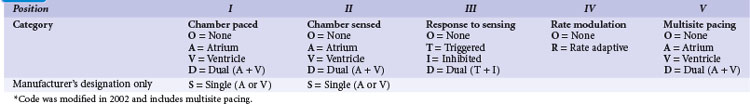
It is necessary to have a basic understanding of the operational modes of the pacemakers. The pacing systems are single chamber, limited to either atrium or ventricle, or systems may be dual chamber. Systems may sense in one chamber and pace the other, sense one and pace both, or sense and pace both chambers. Their functionality can vary from beat to beat, depending on the programmed mode and the underlying rhythm. As a result of a joint approach of the North American Society of Pacing and Electrophysiology (NASPE) and British Pacing and Electrophysiology Group (BPEG), an NBG (NASPE and BPEG Generic) Code was developed (Table 28-1). The latest revision in 2002 incorporates multisite pacing.2
 Single-Chamber Pacing Modes and Timing Cycles
VVI Mode
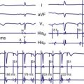
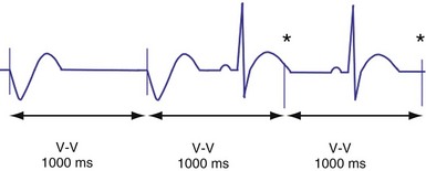
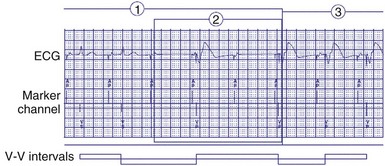
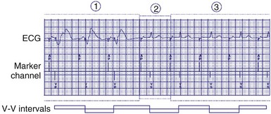
In the VVI mode, the ventricular inhibited pacing mode, the pacemaker senses and paces in the ventricle. This mode is most appropriate for patients in chronic atrial fibrillation (AF) in whom atrial sensing or pacing is not needed. Patients who require infrequent pacing may sometimes be programmed to the VVI mode. In the VVI mode, following a sensed intrinsic ventricular activation (R wave) or a paced event (V), the pacemaker waits for the next intrinsic beat. However, if the escape interval elapses before a ventricular signal is sensed, the pacemaker delivers a ventricular pacing stimulus. Any sensed or paced ventricular event initiates the ventricular escape interval. Intrinsic events may occur at intervals shorter than the escape interval, but the longest time between any two ventricular events is the ventricular escape interval (Figs. 28-1 and 28-2). The escape interval defines the lower rate limit (usually expressed in pulses per minute), which may also be called the minimum or basic (or base) pacing rate. The timing of ventricular sensed events is initiated when the intrinsic signal reaches the necessary sensing threshold after passing through specific amplifiers and filters. The point in the intrinsic signal that is sensed may be delayed compared to the onset of the ventricular activation of the surface electrocardiogram (ECG). The largest amount of delay in sensing of the intrinsic signal from a right ventricular apical lead occurs in the setting of right bundle branch block.
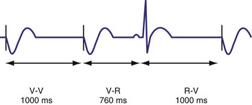
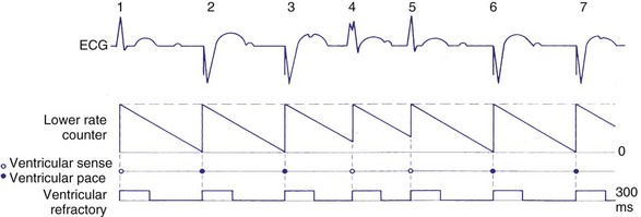
Figure 28-2 Diagrammatic representation of VVI mode of pacing (rate = 80 pulses per minute).
(From Lendermans FW: Diagrammatic representation of pacemaker function. In Barold SS, editor: Modern cardiac pacing, Mt Kisco, NY, 1985, Futura, pp 323-353.)
Ventricular Blanking and Refractory Periods
To sense and pace within the same chamber, “same chamber” refractory periods must be included to avoid inappropriate oversensing of the intrinsic event or pacing3,4 (Fig. 28-3). Immediately following a ventricular paced event, during a ventricular blanking period (VBP) or time interval (ranges from 50-100 msec), all ventricular sensed events are “blanked” or not sensed. The VBP is designed to prevent oversensing of the afterpotentials from pacing stimuli. After this period of absolute lack of sensing, there is a ventricular refractory period (VRP), a programmable time window (usually expressed in milliseconds) during which the pacemaker sensing amplifier is active but does not use the ventricular sensed event to reset the timing cycle. Noise sampling may occur during the VRP, which is used to prevent oversensing caused by the paced evoked potentials, the intrinsic ventricular electrogram (VEGM), or repolarization signals (T wave).
Ventricular Oversensing and Undersensing
Ventricular sensing may result in abnormalities in the ventricular timing cycles. The pacemaker senses an event that does not represent ventricular depolarization. Parts of the QRS complex, the T wave,5 afterdepolarizations,6 atrial activity,7,8 noise from lead abnormalities,9 myopotentials, and electromagnetic interference (EMI) are possible causes of ventricular oversensing.10,11 In ventricular oversensing the additional sensed event will reset the ventricular escape interval, resulting in longer intervals than the programmed pacing cycle length (Fig. 28-4). In ventricular undersensing the pacemaker does not sense an intrinsic ventricular depolarization (R wave). The ventricular escape interval is not reset by this R wave, but instead is created by the previous sensed or paced event. The pacing interval will be shorter than the pacing cycle length (Fig. 28-5).
Hysteresis Rate
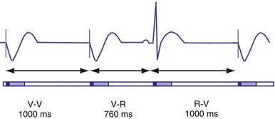
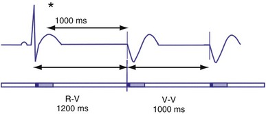
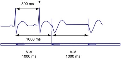
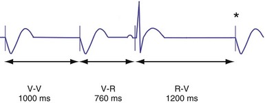
Hysteresis provides for a longer ventricular escape interval from the last ventricular sensed event to the first ventricular paced event (R-V, hysteresis interval) but no change in the time from the last ventricular paced event12 (Fig. 28-6). Hysteresis allows the intrinsic heart rate to be lower before pacing occurs, but when pacing occurs, it will occur at a faster rate. For example, if the hysteresis pacing rate is 50 beats per minute (bpm) and the base pacing rate is 60 bpm, pacing will not occur if the patient continues to maintain rates above 50 bpm. When the heart rate falls below 50 bpm, however, pacing will occur at 60 bpm. This feature favors intrinsic activation and facilitates conduction in the patient with AF or atrioventricular (AV) synchrony in the patient in sinus rhythm. When hysteresis is programmed on, the maximum V-to-V interval (defined by the lower rate interval) is shorter than the maximum R-to-V interval (defined by the hysteresis interval). Hysteresis is often expressed as an absolute rate (beats per minute) or interval (milliseconds) from the intrinsic R wave to the first ventricular paced event (V). Hysteresis may also be expressed as the difference between the hysteresis rate and the pacing rate, or the difference between the hysteresis escape interval (R-V) and the pacing escape interval (V-V). The hysteresis rate is sometimes expressed as a percentage subtracted from the lower rate. The hysteresis often results in a decreased frequency of pacing by allowing more time to expire after an intrinsic event. Typically, the lower rate interval is set to the slowest rate that is desirable hemodynamically. Once pacing occurs, however, it will continue until the intrinsic ventricular rate exceeds the pacing rate.
VOO Mode
In the VOO mode, ventricular pacing without ventricular sensing is present (Fig. 28-7). No intrinsic events are sensed, and therefore ventricular pacing occurs independent of the intrinsic rhythm. VOO is programmed on to prevent EMI from resulting in ventricular inhibition in the pacemaker-dependent patient.
AAI Mode
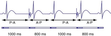
In the AAI mode, the atrial inhibited pacing mode, the pacemaker will deliver an atrial pacing stimulus at the end of the atrial lower rate limit, measured from the previous paced or sensed atrial event. If the atrial channel does not sense an intrinsic atrial event, and the programmed lower rate limit has expired, the pacemaker will deliver an atrial impulse (Fig. 28-8). Timing is based on intrinsic atrial sensed events (P) or atrial paced events (A). The intervals used in timing can be described as P-P, P-A, A-A, and A-P. Conceptually, the timing intervals in the AAI pacing mode are similar to those of the VVI pacing mode. However, it is important to note that in the AAI mode, only atrial events, and not ventricular events, will result in reset of the timing cycle (Fig. 28-9).
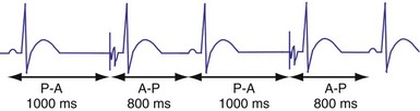
Figure 28-9 AAI pacing.
(From Barold S, Zipes D: Cardiac pacemakers and antiarrhythmia devices. In Braunwald E, editor: Heart disease: a textbook of cardiovascular medicine, ed 4, Philadelphia, 1992, Saunders, pp 726-755.)
Individual physician and regional practice variations exist, but generally the best-suited candidates for the AAI mode are patients who are in sinus rhythm and have intact AV conduction. Because this mode does not pace the ventricle, it is not appropriate for patients who are suspected to have compromised A-V conduction.13 The ability to maintain 1 : 1 AV conduction during atrial pacing at rates of 120 or 130 bpm or faster during the pacemaker implant procedure is frequently used to determine the absence of significant AV conduction abnormalities. Recent concern about the possibly deleterious impact of ventricular pacing has increased the interest in atrial pacing.14
Atrial Periods and Hysteresis
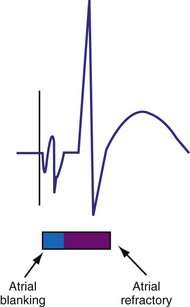
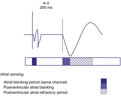
The atrial refractory period (ARP) is similar to the VRP and constitutes a time interval after a paced or sensed atrial event in which the pacemaker is refractory to spontaneous atrial signals (Fig. 28-10). It is also divided into an atrial blanking period (ABP), often programmable, followed by a refractory period during which noise sampling occurs (Fig. 28-11). The ABP is used primarily to prevent sensing of afterpotential of the pacing stimulus. The ARP (ranges from 150-500 msec) is used to prevent the atrial lead from oversensing the afterpotential of a paced stimulus, the local evoked potential produced by atrial pacing stimulus, or “far-field” sensing of the ventricular depolarization.
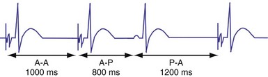
Atrial hysteresis may also be used in the AAI mode. The P-A interval, the atrial escape interval, is longer than the A-A interval, the atrial pacing interval. Atrial hysteresis, similar to ventricular hysteresis, may be used to minimize atrial pacing (Fig. 28-12).
 Bradycardia Timing Cycles
Dual-Chamber Timing Cycles
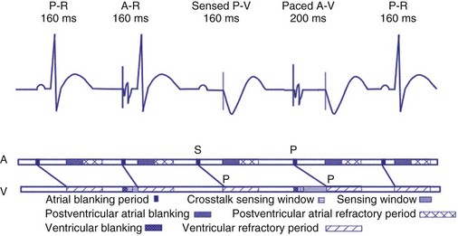
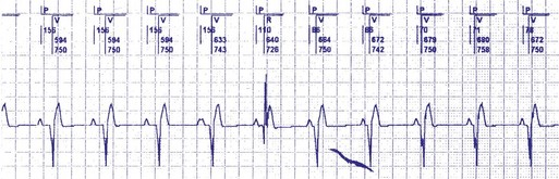
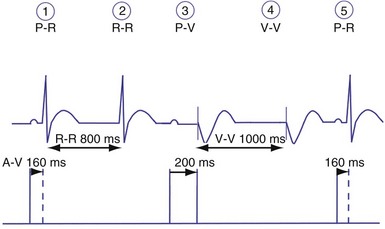
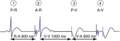
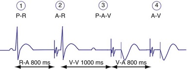
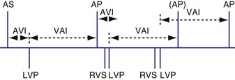
Dual-chamber devices in the DDD mode provide a mechanism to combine pacing and sensing in either or both chambers.15–17 These functions include pacing in both the atrium and the ventricle, inhibition of pacing by sensed events in the respective chamber, and AV coordinated pacing (Fig. 28-13). A sensed intrinsic atrial event inhibits atrial pacing, and a sensed intrinsic ventricular event inhibits ventricular pacing. An atrial sensed event that occurs before the atrial escape interval has “timed out” is “tracked,” or followed by a ventricular paced output. Timing is based on atrial sensed events (P), atrial paced events (A), ventricular sensed events (R), and ventricular paced events (V). Intervals between atrial and ventricular events can be described as A-R, A-V, P-R, and P-V (Fig. 28-14).
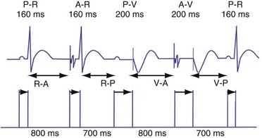
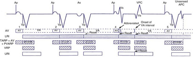
Figure 28-14 Diagrammatic representation of the function of a DDD pacemaker.
(From Barold S, Zipes D: Cardiac pacemakers and antiarrhythmia devices. In Braunwald E, editor: Heart disease: a textbook of cardiovascular medicine, ed 4, Philadelphia, 1992, Saunders, pp 726-755.)
Atrioventricular Interval
The atrioventricular interval (A-V interval, AVI) is a programmable parameter that determines the maximum time after an atrial event during which an intrinsic ventricular event can occur before delivery of a ventricular pacing stimulus (see Fig. 28-13). It is initiated after a sensed or a paced atrial event. AVI is similar to the native P-R interval and thus is programmed to optimize the hemodynamic benefit of AV coordination. AVI permits atrial contraction resulting in ventricular filling in end-diastole. AVI is programmed at rest to maintain coordinated timing of atrial and ventricular contractions, allowing intrinsic AV conduction when possible, and conserve generator energy. Patients who do not have coordinated AV contractions from PR prolongation may have impaired left ventricular filling, because atrial contraction occurs much earlier than the ventricular contraction. Recent trials involving patients with both preserved and depressed ventricular function suggest maintaining intrinsic AV conduction and minimizing right ventricular pacing is also desirable hemodynamically, because improved ventricular contraction and cardiac output are seen with normal ventricular activation.
Therefore the clinician balances permitting a short enough A-V interval to optimize coordination of AV contraction with permitting sufficient time for conduction to result in intrinsic ventricular activation. The programmed A-V interval that results in optimal hemodynamics may vary considerably and may be difficult to predict accurately. Many clinicians select the programmed A-V interval that allows a P-R interval of up to 280 to 300 msec. Assessment of interatrial conduction delay may have a role in setting the optimal A-V interval, but data are still limited.18 There may be a time differential with atrial activation depending on whether the atrium is paced or is activated intrinsically. Usually, the time for a paced electrical impulse to result in atrial activation is longer than the time required for intrinsic atrial activation. A differential A-V interval may be programmed, as discussed later. Also, to conserve battery energy, the clinician may extend the AVI in patients without AV block to reduce pacing.
Crosstalk and Ventricular Safety Pacing
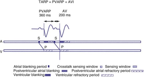
Crosstalk is the inappropriate sensing of far-field signals from the opposite cardiac chamber, causing pacing inhibition or oversensing. One of the most serious manifestations of crosstalk in a dual-chamber pacing system is oversensing of far-field atrial stimuli, resulting in ventricular inhibition and asystole in the “pacemaker-dependent” patient. The AVI thus encompasses multiple refractory and blanking intervals on each atrial/ventricular channel, as well as on the “opposite” channel to prevent crosstalk (Figs. 28-14 and 28-15).
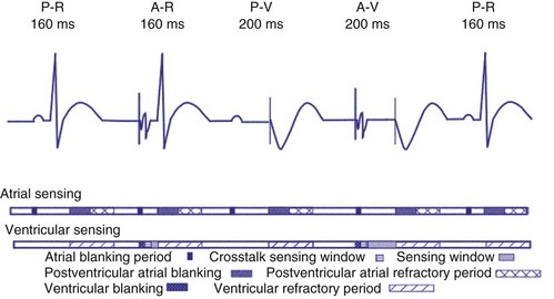
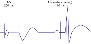
An atrial pacing output also initiates multiple timing windows on the ventricular channel. Atrial pacing output triggers a VBP at the beginning of the A-V interval in an attempt to avoid oversensing the atrial stimulus artifact on the ventricular lead (Fig. 28-16). This absolute VBP is usually short, ranging from 20 to 44 msec, and may be programmable in certain pacemaker models. Immediately after the VBP, the ventricular sensing amplifier becomes active during the ventricular safety pacing (VSP, or crosstalk sensing) window in the second portion of the AVI (up to 80-120 msec). Signals sensed during the “crosstalk sensing window” (<120 msec from the atrial pacing output) are considered “nonphysiologic” because of the close coupling interval and may be caused by oversensing of atrial pacing afterpotentials, spontaneous premature ventricular depolarizations, or noise (see Fig. 28-16). VSP is designed to prevent inappropriate inhibition of the ventricular pacing caused by crosstalk (Figs. 28-17 and 28-18). After an atrial paced depolarization, if there is a sensed event occurring during the VSP window, instead of inhibiting ventricular pacing, the pacemaker will deliver a ventricular pacing stimulus at a shortened A-V interval, typically 80 to 130 msec. The shortened A-V interval makes the identification of VSP apparent and decreases the likelihood of a ventricular paced event occurring during ventricular repolarization, particularly if the baseline A-V interval is relatively long, minimizing the risk of ventricular proarrhythmia. Crosstalk in this situation is most likely to occur in the presence of high atrial pacing output (e.g., 6 V at 1 msec) along with high ventricular sensitivity (e.g., 2 mV). VSP may also be seen when atrial undersensing occurs and the conducted intrinsic ventricular beat is sensed in the crosstalk safety pacing window (Fig. 28-19).
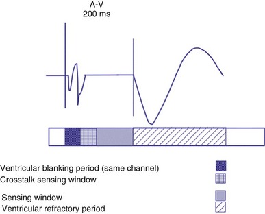
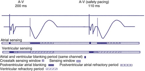
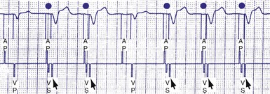
Figure 28-18 Ventricular safety pacing.
(From Barold S, Zipes D: Cardiac pacemakers and antiarrhythmia devices. In Braunwald E, editor: Heart disease: a textbook of cardiovascular medicine, ed 5, Philadelphia, 1997, Saunders, pp 705-741.)
On the atrial channel, a paced event may result in an absolute ABP, preventing sensing of afterpotential of the pacing stimulus (Fig. 28-20). In some devices, a sensed atrial event also initiates an ABP. After the APB, atrial sensed events may be used for detection of pathologic atrial tachyarrhythmia for mode switching, overdrive suppression algorithm, or noise reversion. After a ventricular sensed or paced event, there may be a postventricular atrial blanking period, to prevent the sensing of ventricular paced events or far-field ventricular sensed events on the atrial channel. After a ventricular paced or sensed event, a postventricular atrial refractory period (PVARP) is created (see Fig. 28-20). During PVARP, atrial events are refractory sensed events and do not affect timing of events (see later).
Differential AVI
In some devices, the AVI initiated after a sensed atrial event (SAV) can be different from the AVI initiated after a paced atrial event (PAV). This difference in the SAV and PAV is called a differential AVI. The optimal A-V interval achieves coordination of the atria and ventricles, particularly left atrium and left ventricle. Usually, impulse formation starts in the sinus node and travels to the right atrial lead on its way to the AV node. Thus, by the time the event is sensed on the atrial channel, contraction of the atria has already begun, necessitating only relatively short delay to the time that ventricular excitation occurs. Time elapses between the initiation of an intrinsic atrial depolarization and the point that most of the atria are depolarized. This delay is determined by the distance from initiation to the location of the lead, as well as conductive properties of the atrial tissue. By the time the atrial lead has sensed the intrinsic depolarization, it has already gotten a “head start” to the AV node compared to an atrial paced event. By programming the AVI of a sensed atrial depolarization (PV) to be shorter than that after an atrial paced event (AV), the time to ventricular pacing after a paced atrial beat will be similar to that after a sensed atrial event (Fig. 28-21). This is an attempt to provide a more physiologic AV synchrony. The SAV may be expressed as a percentage of the PAV, or as an absolute difference (up to 100 msec) between the two differential A-V intervals.
Rate-Adaptive or Dynamic Atrioventricular Delay
The shortening of AVI with exercise provides optimal AV synchrony and is designed to mimic the normal physiologic shortening of the P-R interval. The programmable parameter called rate-adaptive or dynamic A-V interval permits the modulation of sensed or paced AVI based on the ventricular rate, either intrinsic or sensor driven. In addition to the hemodynamic benefit of shortening the AVI, rate-related shortening of AVI decreases the total atrial refractory period (see Upper Rate Behavior), allowing a correspondingly higher, 2 : 1 atrial tracking rate. The changes in dynamic AVI may be linear or nonlinear based on the sensed atrial rate or the sensor-driven rate and are programmed from a baseline AVI to a “minimum AVI.”
Atrioventricular Interval Hysteresis
The AVI can also be modulated based on the presence or absence of AV conduction, with a sensed ventricular event during AVI, a feature called “positive” or “negative” AV/PV hysteresis. The term “AV hysteresis” is generally used to describe adaptations of either paced or sensed AVI relative to patient’s intrinsic P-R interval. Similar to heart rate hysteresis, AVI hysteresis is a prolongation of AVI in response to a ventricular sensed event (R), called “positive AV/PV hysteresis.” The longer-than-programmed A-V interval permits intrinsic AV conduction and minimizes unnecessary ventricular pacing. Positive AV/PV hysteresis is most beneficial to patients who have variable AV conduction. However, if the intrinsic AV conduction exceeds the AVI hysteresis and no spontaneous R wave was sensed at the end of the AVI (as in AV block), A-V interval is shortened to the original programmed value. A search function extends the A-V interval periodically from the programmed baseline value to the longer AVI hysteresis interval to promote intrinsic AV conduction and ventricular activation (Figs. 28-22 and 28-23). This function may be called “search positive AV hysteresis”; alternatively, “negative AV/PV hysteresis” is programmed to promote and maintain ventricular pacing and avoid fusion. After an atrial event, if native ventricular conduction is sensed (R wave), the next AVI will be shortened to promote ventricular pacing and capture (Fig. 28-24). This function may be used to promote ventricular capture, when this is hemodynamically desirable. Such conditions might include pacing for hypertrophic cardiomyopathy or biventricular pacing.
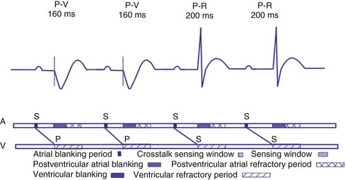
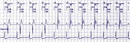
Figure 28-23 Positive AVI hysteresis.
(Courtesy St. Jude Cardiac Rhythm Management Division, Sylmar, Calif).
Postventricular Atrial Refractory Period
After a sensed or paced ventricular event, atrial sensed events do not result in a corresponding A-V interval for a programmable period of time. The PVARP is used to prevent sensing of retrograde P waves following a paced or sensed ventricular event usually not preceded by an atrial or paced event (Fig. 28-25). The atrial channel may sense a retrograde atrial signal as an intrinsic event and trigger ventricular pacing, resulting in another ventricular paced event, which also conducts retrograde. This repetitive sequence is known as pacemaker-mediated tachycardia (PMT), which may continue without intervention (Figs. 28-26 and 28-27). PMT may occur at or below the maximum tracking rate and is often induced by spontaneous premature ventricular beats or loss of atrial capture. The rate of PMT depends on the retrograde conduction time, the programmed A-V interval, and the maximum tracking rate. PMT usually occurs at the maximum tracking rate. However, the retrograde conduction time may be long enough to permit tracking of the atrial event with the programmed A-V interval so that the PMT rate may be less than the maximum tracking rate. To avoid PMT, the PVARP is usually programmed longer than the retrograde conduction time; however, if it is programmed excessively long, the sum of the PVARP and the A-V interval, the total atrial refractory period will determine the rate at which one ventricular paced event occurs for two atrial sensed events, the 2 : 1 atrial tracking rate (see next).
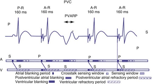
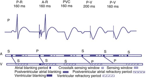
Figure 28-27 Pacemaker-mediated tachycardia terminated and initiated by ventricular extrasystole.
(From Barold SS, Falkoff MD, Ong LS, Heinle RA: Basic concepts, upper rate response, retrograde ventriculoatrial conduction, and differential diagnosis of pacemaker tachycardias. In Saksena S, Goldschlager N, editors: Electrical therapy for cardiac arrhythmias: pacing, antitachycardia devices, catheter ablation, Philadelphia, 1990, Saunders, pp 225-264.)
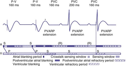
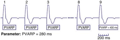
Extension of PVARP in response to a premature ventricular complex (PVC), called the “PVC PVARP extension” (or response), is available in many devices. This algorithm is designed to lengthen the PVARP and to avoid sensing of a retrograde P wave following a premature ventricular beat, which may cause initiation of PMT. Of note, a “PVC” is usually defined by the pacemaker as a “spontaneous ventricular depolarization” without a preceding atrial paced or sensed event. In some cases, a long PVARP may lead to absence of atrial tracking (Fig. 28-28). Similarly, oversensing of a T wave and programming on the PVC PVARP extension may cause perpetuation of absence of atrial tracking at rates below the lower rate limit (Fig. 28-29). Repetitive functional atrial undersensing may occur in the absence of PVC PVARP extension, particularly when the AV conduction is prolonged and the intrinsic A-V interval plus PVARP is longer than the sinus cycle length.19 Features such as “autointrinsic search” that cause prolongation of AV conduction may result in PMT by permitting retrograde conduction.20
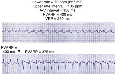
Figure 28-28 Lack of P-wave tracking caused by long PVARP (400 msec).
(From Barold SS, Falkoff MD, Ong LS, Heinle RA: Timing cycles of DDD pacemakers. In Barold S, Mugica J, editors: New perspectives in cardiac pacing, Mt Kisco, NY, 1988, Futura.)
Upper Rate Behavior
In patients in the DDD, DDDR, VDD, or VDDR modes, one-to-one (1 : 1) ventricular tracking of the intrinsic atrial activity is hemodynamically desirable. However, tracking of atrial arrhythmias may result in rapid ventricular pacing and result in unfavorable hemodynamics. Therefore, these tracking modes have a parameter to limit the fastest rate that the atrium can be tracked. The fastest rate at which atrial activity can be tracked 1 : 1 to the ventricle is known as the upper rate, also called the maximum tracking rate (MTR), with a corresponding upper rate interval or maximum tracking interval (Fig. 28-30). In DDD mode, whether atrial or ventricular based, when the intrinsic atrial activity is faster than the programmed upper rate limit, “upper rate behavior” will be seen. Atrial rates above the MTR can still be sensed and tracked. However, delays in subsequent ventricular paced beats occur so that the ventricular rate does not exceed the programmed MTR (Fig. 28-31). This effectively prolongs the AVI. The A-V interval is further extended on repeated cycles, and the subsequent atrial depolarization eventually falls within the PVARP. Because the atrial event occurs within the PVARP, it is not sensed by the atrial channel and thus does not lead to ventricular pacing. The next atrial event, however, can be tracked and can cause ventricular pacing. The pattern that emerges is increasing duration between intrinsic atrial sensed events and ventricular paced events until an atrial event is not followed by a ventricular paced beat. Such behavior is similar to a Wenckebach period during AV conduction and is called “pseudo-AV Wenckebach.” The A-V interval extension is greatest when the P wave occurs just after the completion of the preceding PVARP (Fig. 28-32). A-V interval extension may be seen at constant atrial rates during atrial or sinus tachycardias as well as during atrial premature beats (Fig. 28-33).
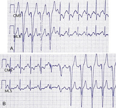
Figure 28-30 Upper rate behavior.
(From Douard H, Barold SS, Broustet JP: Too much protection may be a nuisance. Stimucoeur 25:183-187, 1997).
Figure 28-31 DDD mode upper rate response with Wenckebach pacemaker AV block.
(From Barold SS, Falkoff MD, Ong LS, Heinle RA: All dual-chamber pacemakers function in the DDD mode. Am Heart J 115:1353-1362, 1988.)
Figure 28-32 Diagrammatic representation of the mechanism of A-V interval prolongation.
(In Barold SS, Falkoff MD, Ong LS, Heinle RA: Basic concepts, upper rate response, retrograde ventriculoatrial conduction, and differential diagnosis of pacemaker tachycardias. In Saksena S, Goldschlager N, editors: Electrical therapy for cardiac arrhythmias: pacing, antitachycardia devices, catheter ablation. Philadelphia, 1990, Saunders, pp 225-264.)
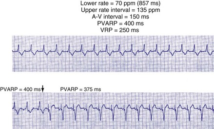
If the intrinsic atrial rate continues to increase above the MTR, it will eventually reach the 2 : 1 AV tracking rate, defined by the total atrial refractory period (TARP), which is the sum of the PVARP and the AVI (Fig. 28-34). The TARP defines the period during which sensing may occur and limits the MTR. TARP determines the rate at which atrial tracking occurs in a 2 : 1 ratio. At this atrial rate, every other P wave falls into the PVARP and is not sensed. If the intrinsic atrial rate is fast enough, one P wave can fall within the TARP while the next P wave falls outside the TARP and is tracked. If the atrial rate is slightly faster, the first P wave will be tracked and the second P wave fall just within the PVARP and is not tracked. As a result, for every two intrinsic atrial events, there is one ventricular paced beat. Such a phenomenon occurs when the intrinsic atrial rate is faster than the 2 : 1 AV block rate. The 2 : 1 AV block rate can be calculated as 60,000 (in msec) divided by TARP (in msec). For example, for an AVI of 150 msec and PVARP of 250 msec, ventricular pacing may follow atrial sensing at a 1 : 1 rate up to 149 bpm. At a sinus rate of 150 bpm, 2 : 1 atrial tracking occurs and the ventricular rate abruptly drops to 75 bpm.
There may be limitations to minimizing TARP because of retrograde conduction necessitating a PVARP to be programmed longer than the retrograde conduction time. To avoid precipitous falls in heart rate, it is preferable to have the 2 : 1 AV block rate set above the MTR to accommodate high intrinsic sinus rates without sudden AV block. This is achieved by minimizing TARP, with several common ways to reduce TARP and raise the 2 : 1 block rate. The PVARP can be shortened (with increased risk of PMT), and the AVI can be programmed to be rate adaptive and to shorten with faster ventricular rates. Rate-adaptive or dynamic PVARP is also available in some models, which shortens PVARP at a faster rate and thus reduces TARP and increases the 2 : 1 AV block rate. Caution should be used with rate-adaptive PVARP to confirm that retrograde conduction will not occur at rapid ventricular rate, so that the conduction time does not exceed the PVARP, resulting in PMT. Alternatively, the pacemaker can be programmed to DDDR mode and can rely on the sensor to drive pacing during exertion. If sensor-driven ventricular pacing occurs close to the sinus rate, the ventricular pacing rate will closely follow the sinus rates, even though the ventricular pacing rate exceeds the atrial MTR. This phenomenon has been termed sensor-driven rate smoothing and resembles tracking above the MTR (Fig. 28-35).
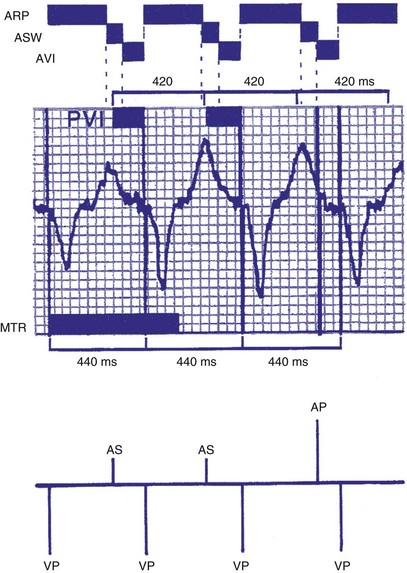
Figure 28-35 Sensor-driven appearance of atrial tracking.
(From Higano ST, Hayes DL: P wave tracking above the maximum tracking rate in a DDDR pacemaker. Pacing Clin Electrophysiol 12:1044-1048, 1989.)
Upper rate behavior may also result in triggering an apparent failure to sense P waves because the P wave falls within PVARP, and the subsequent QRS complexes are categorized as premature ventricular beats. An algorithm to increase the PVARP following a PVC may result in prolonged absence of atrial tracking (Figs. 28-36 and 28-37). Upper rate behavior may also be characterized by intrinsically conducted beats that may preempt the ventricular paced beats at the upper rate. Barold et al.21 describe a relatively short programmed A-V interval, a sinus rate faster than the programmed upper rate, a relatively slow programmed upper rate, and relatively normal AV conduction as most likely to be associated with this phenomenon.
Figure 28-36 Apparent P-wave undersensing.
(From van Gelder BM, van Mechelen R, den Dulk K, el Gamal M: Apparent P wave undersensing in a DDD pacemaker after exercise. Pacing Clin Electrophysiol 15:1651, 1992.)
Lower Rate Behavior: Atrial- versus Ventricular-Based Timing
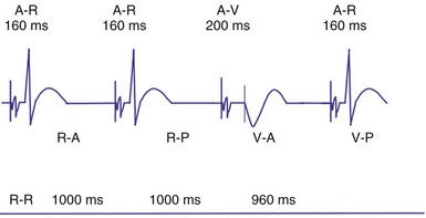
In ventricular-based timing, the effective ventricular rate can be faster than the programmed LRL. This occurs in patients with intact AV conduction and is mainly caused by the difference between the paced AVI and the shorter, intrinsic AV conduction. For example, in a pacemaker programmed to an LRL of 60 bpm (1000 msec) that has a programmed AVI of 200 msec, the AEI is 800 msec (LRL − AVI = AEI). If AV conduction is present at 150 msec, the sensed R wave will reset the timing cycle, whereas the AEI is “fixed” at 800 msec. The effective interval between consecutive atrial pacing is thus 950 msec (AEI + A-R), which is approximately 63 bpm (Figs. 28-38 and 28-39). In patients with intact AV conduction, the effective ventricular rate can be faster than the programmed LRL in a ventricular-based timing system.
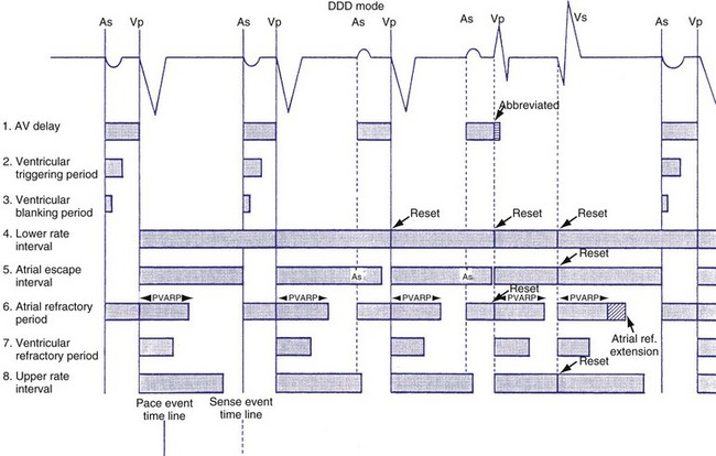
Figure 28-38 DDD mode with ventricular-based lower rate timing.
(From Barold SS, Falkoff MD, Ong LS, et al: All dual-chamber pacemakers function in the DDD mode. Am Heart J 115:1353, 1988.)
Compared to a ventricular-based timing in which the AEI is fixed, the atrial interval (A-A) is fixed in atrial-based timing. A sensed R wave occurring during AVI inhibits ventricular output but does not reset the basic A-A interval, and thus LRL is not altered. When an R wave is sensed during AEI, the A-A interval is reset, but not the AEI. This results in a longer atrial-to-atrial interval, which simulates a physiologic “compensatory” pause. Some pacemaker models deploy a “modified” atrial-based algorithm, such that routine atrial sensed or paced events reset the A-A timing cycle, whereas premature ventricular beats reset the AEI or the V-A interval (Fig. 28-40). Early sensing of the ventricular complex on the atrial channel (crosstalk) in a pacemaker with atrial-based timing may result in prolonged AEIs22 (Figs. 28-41 and 28-42). In Figure 28-41, A, at greater ventricular sensitivity there is no evidence of a prolonged AEI, while at less ventricular sensitivity (B), AIE is significantly prolonged. Figure 28-42 reveals that the first PVC may be sensed first on the atrial channel, resulting in prolongation of the AEI. In this device, when PVCs are sensed first on the ventricular channel, ventricular-based timing is used to set AEI. The second PVC in the figure is sensed as a PVC and thus does not result in AEI prolongation.
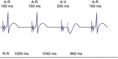
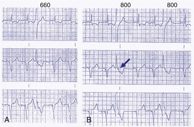
Figure 28-41 Prolongation of atrial escape interval in atrial-based timing pacemaker.
(From Barold SS: Far-field R-wave sensing causing prolongation of the atrial escape interval of DDD pacemakers with atrial-based lower rate timing. Pacing Clin Electrophysiol 26:2188-2191, 2003.)
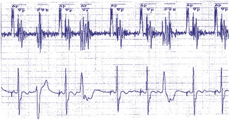
Figure 28-42 Prolongation of atrial escape interval in atrial-based timing pacemaker.
(From Barold SS: Far-field R-wave sensing causing prolongation of the atrial escape interval of DDD pacemakers with atrial-based lower rate timing. Pacing Clin Electrophysiol 26:2188-2191, 2003.)
The response to a PVC varies based on the individual manufacturer’s timing cycles. A PVC may result in initiation of the entire lower rate interval in milliseconds (60,000 divided by lower rate in beats per minute) before initiating an atrial paced event, resulting in an R-R interval that is longer than the lower rate interval (Biotronik). On the other hand, the interval from the PVC to the atrial paced event is equal to PVARP plus 330 msec in another timing cycle schema (St. Jude). If an atrial event is sensed within the PVARP, the interval to the atrial paced event is 330 msec (St. Jude). In remaining cases, AEI is equal to the lower rate interval minus the programmed A-V interval (Medtronic, Boston Scientific, ELA/Sorin).23
Sensor-Driven or Adaptive-Rate Pacing
Pacemaker-Mediated Tachycardia Algorithms
Some algorithms may classify an atrial sensed and ventricular paced rhythm as PMT if atrial tracking occurs at a specific rate. The PMT detection rate may be the upper tracking rate or a rate above the upper tracking rate. Other algorithms detect PMT if repetitive atrial sensing follows ventricular pacing with a consistent V-A interval of less than 400 msec (compatible with retrograde VA conduction). When PMT is detected, different responses can occur. Some devices will extend the PVARP, whereas others will suspend atrial tracking for one cycle, causing PMT to terminate (Fig. 28-43). In some generators, sensor activity is used in combination with the atrial sensed rate to determine if PMT is present. For example, with eight consecutive intervals with a VA time of less than 400 msec, and if the atrial rate is less than the sensor-determined rate of activities of daily living, PMT is diagnosed and a PMT termination algorithm initiated (Medtronic). In another algorithm, the PMT detect rate may be programmed from 90 bpm to the MTR. In one strategy, if 10 beats occur at a rate greater than the PMT rate, the PVARP is extended to 480 msec (St. Jude).24
Mode Switching
Automatic mode switch (AMS) refers to the ability of the pacemaker to switch automatically from one mode of operation to another in response to a sensed atrial tachyarrhythmia25–28 (Fig. 28-44). When atrial tachyarrhythmias occur, atrial tracking modes such as DDD(R) or VDD(R) can result in rapid ventricular pacing with resultant hemodynamic compromise. Mode-switching algorithms detect the presence of atrial tachyarrhythmias and convert the pacemaker to a nonatrial tracking mode such as VVI(R) or DDI(R). In some cases, mode switching in DDD may result in either DDI or DDIR. An alternative mode switch is VDI or VDIR. Before mode switching, there may be a period of atrial tracking resulting in short paced intervals. Once mode switching is confirmed, the mode changes to the nonatrial tracking mode and the rate gradually decreases to the LRL.
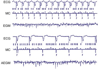
Figure 28-44 Activation of mode-switching function from DDDR to DDIR.
(From Lau CP, Leung SK, Tse HF, Barold SS: Automatic mode switching of implantable pacemakers. I. Principles of instrumentation, clinical, and hemodynamic considerations. Pacing Clin Electrophysiol 25:967-983, 2002.)
Mode-switching functions are often programmable. The algorithms vary but may be triggered by a specific atrial rate threshold, either absolute or averaged (in beats per minute). There is usually a requirement for sustained high rate duration (a number of beats or a time duration) before mode switching occurs. Other devices deploy a “running counter” that increases when the atrial rate is faster and decreases when the atrial rate is slower than a specified rate limit. The pacemaker will switch modes only when the counter has reached a predetermined number. This prevents inappropriate mode switch caused by frequent isolated atrial ectopic beats. Some algorithms permit detection of premature atrial beats on a beat-to-beat basis. Lau et al.25 describe the “perfect” mode-switching system as having (1) rapid onset to avoid rapid ventricular pacing during initial detection of atrial tachyarrhythmias, (2) absence of fluctuation in rate or inappropriate response, (3) ability to restore AV synchrony rapidly after termination of atrial tachyarrhythmia, (4) ability to sense atrial tachyarrhythmias at a variety of rates and signal amplitudes, and (5) ability to avoid response to crosstalk, sinus tachycardia, and extraneous noise.
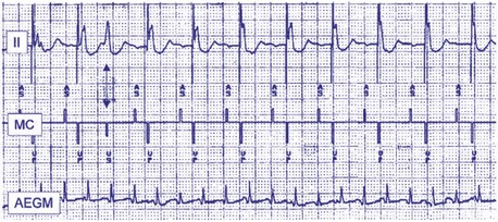
Nonetheless, detection of atrial arrhythmias remains the greatest challenge for mode switching algorithms.29–31 Undersensing is possible because the amplitude of the atrial electrogram (AEGM) may decrease significantly during atrial tachyarrhythmia compared with sinus rhythm. As the atrial channel becomes more sensitive, undersensed events will decrease, but oversensing of noise or extraneous signals may increase (Fig. 28-45). ABP does not usually play a significant role in atrial undersensing during AF.32 Oversensing can also be problematic, such as far-field signals (crosstalk) from ventricular depolarizations, T waves, myopotentials, or environmental noise. In the case of undersensing, mode switching may fail to occur, whereas in oversensing, mode switching may occur inappropriately.
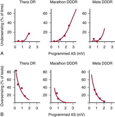
Figure 28-45 Ability to mode-switch depends on atrial sensitivity.
(From Lau CP, Leung SK, Tse HF, Barold SS: Automatic mode switching of implantable pacemakers. I. Principles of instrumentation, clinical, and hemodynamic considerations. Pacing Clin Electrophysiol 25:967-983, 2002.)
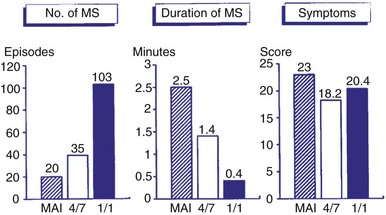
Symptoms are usually minimized during mode switching because of the relatively rapid onset of mode switching. Even when mode switching occurs rapidly, however, some patients may remain symptomatic because of the abrupt change in rate. A comparison of three different mode-switching algorithms downloaded into an implanted pacemaker was made (Fig. 28-46). The mean atrial interval (MAI) was compared to 4 of 7 intervals and 1 of 1 interval as criteria for mode switching; the shorter the criteria, the greater the number of episodes observed. The duration of mode switching decreased with shorter criteria, as expected. The symptoms did not vary significantly.
Atrial Flutter Response
Because atrial flutter may be associated with every other AEGM falling into a blanking period, mode switching during atrial flutter may not reliably occur. A special response may occur when atrial flutter is detected to result in mode switching and to prevent pacing during the atrial vulnerable period.33 If an atrial event is detected within PVARP, a programmable interval is created. Subsequent atrial events sensed within this programmable interval will also not be tracked, and each such event will create another programmable interval. This algorithm permits atrial tracking to be withheld even before mode switching occurs. In addition, atrial pacing does not occur until the programmable interval or PVARP expires. Once the PVARP or the programmable interval expires, atrial pacing may occur if there is at least 50 msec and no more than the AV delay before the next ventricular paced beat.
A related algorithm permits atrial flutter to trigger mode switching. If atrial cycles are sensed at an interval shorter than twice the AV delay plus the postventricular atrial blanking period (PVABP) for eight consecutive cycles, the algorithm extends the PVARP to 400 msec for one cycle (Fig. 28-47). The atrial signal that had been tracked is now refractory and may activate mode switching. Figure 28-48 shows an example of an atrial flutter with an atrial cycle that places an atrial signal within the PVABP so that the atrial flutter response never occurs.
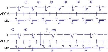
Figure 28-47 Atrial flutter algorithm to trigger mode switching.
(From Israel CW, Barold SS: Failure of atrial flutter detection by a pacemaker with a dedicated atrial flutter detection algorithm. Pacing Clin Electrophysiol 25:1274-1277, 2002.)
Rate Smoothing
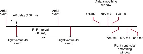
Rate-smoothing algorithms are designed to “smooth” and prevent sudden changes in heart rates accompanied by hemodynamic compromise or symptoms. Sinus arrest may result in an abrupt decrease in heart to the escape rate (e.g., from 80 to 50 bpm). Rate smoothing “down” results in a more gradual decrease in heart rate. The rate of decrease in rate is constrained by the programmed rate-smoothing percentage, usually from 3% to 24%. A rate-smoothing atrial or ventricular window is created that determines when the next atrial paced or ventricular paced event will occur. The ventricular window is created by calculating the previous V-V interval and multiplying by the rate-smoothing percentage. For example, if the previous cycle length was 1000 msec and rate smoothing up was 12% and down was 8%, the width of the rate-smoothing up window would be 120 msec and the down window would be 80 msec. The atrial rate-smoothing window is calculated by subtracting the AV delay from the boundaries of the ventricular rate-smoothing window (Fig. 28-49).
Sudden changes in ventricular rate can also occur in patients with intermittent atrial arrhythmias or AF.34 Tracking of an atrial arrhythmia that may be too transient or too slow to trigger mode switching may result in palpitations or other symptoms because of the abrupt increase in heart rate. Rate smoothing “up” may limit the ventricular rate to avoid the suddenness of the heart rate increase. Mode switching may interact with a variety of other programmed parameters. Ventricular tachycardia prevention algorithms may become inactivated by mode switching.35
Fallback
Fallback response provides a response very similar to rate smoothing by limiting the rate of the heart rate change.36 Fallback may occur when the rate decreases from URL tracking to the LRL during mode switching or other rate-drop response.
Rate-Drop Response
Patients who experience neurocardiogenic or vasovagal syncope become symptomatic when the heart rate falls precipitously. The rate-drop response (RDR) algorithm is designed to recognize a rapid decline in heart rate using a heart rate duration detection window. The degree of rate drop (in beats per minute) within the specified duration (in number of beats) is programmable. The newer algorithm uses an averaged ventricular baseline rate as the reference. Once the RDR is triggered, dual-chamber pacing is then initiated at a relatively fast rate, either an absolute rate (100-120 bpm) or a relative rate (70% or 80% of maximum heart rate) (Fig. 28-50). The sudden bradycardia response (SBR) is another example of this type of rate algorithm. This response is initiated by a decline in the atrial rate by more than 10 bpm for a programmed number of beats (1 to 8) based on a weighted average serving as the baseline rate. The SBR consists of pacing at a rate that is 5 to 40 bpm faster than the previous rate.
Prevention of Atrial Fibrillation
There has been considerable interest in using atrial pacing for prevention of AF.37–41 The Pacemaker Selection Trial for the Elderly (PASE) study and the Canadian Trial of Physiological Pacing (CTOPP) showed that atrial pacing or dual-chamber pacing is associated with a lower occurrence of AF compared with ventricular pacing alone.42–44 Pacing from sites other than the right atrium, such as the atrial septum or Bachmann’s bundle, has been shown to decrease the incidence of AF. Atrial pacing at two sites, such as the right atrium and coronary sinus ostium (CS os), has also been examined for its effect on AF. Multisite atrial pacing has shown varying efficacy in AF prevention.
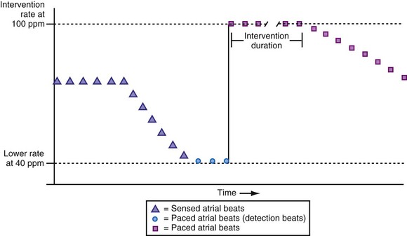
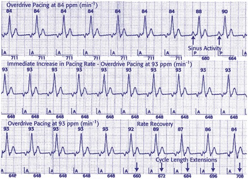
Specific atrial pacing algorithms have been studied as possible methods of decreasing AF. Prospective randomized trials, such as the Atrial Dynamic Overdrive Pacing Trial (ADOPT) and Overdrive Atrial Septum Stimulation (OASIS) trial, demonstrated significant reductions in AF burden using the AF suppression algorithm (St. Jude Medical). Continuous atrial overdrive pacing is maintained by setting the atrial lower rate higher than the intrinsic sinus rate. The atrial pacing rate is adjusted in response to either the mean atrial rate or the occurrence of premature atrial beats. AF pacing parameters may be set to stimulate the atrium at rates faster than the intrinsic atrial rate to suppress the triggers of AF (Fig. 28-51). When two P waves are detected within a 16-cycle window, the atrial pacing algorithm is initiated. The pacing occurs for a programmable number of pacing cycles, a programmable number of intervals, and then the interval is gradually decreased. Atrial pacing preference (APP) paces in response to the atrial rate but not to premature atrial beats. In contrast, atrial pacing may specifically respond to atrial pacing in a specific interval. The atrial overdrive in a DDD(R) mode is triggered whenever two spontaneous P waves are sensed in a 16-beat window. The extent of atrial overdrive is a nonprogrammable parameter, determined by the instantaneous atrial rate. The continuous atrial pacing algorithm also increases atrial pacing and paces at 30 msec shorter than the intrinsic atrial cycle length. A double-algorithm approach alters pacing in response to atrial premature beats (used by the Medtronic AT 500). However, such high rate overdrive pacing may result in undersensing because of a short atrial sensing window. Rare cases of proarrhythmia have been reported.
Noncompetitive Atrial Pacing
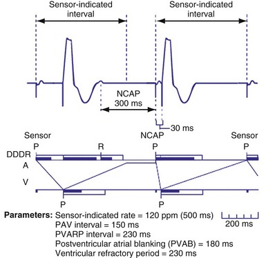
To prevent atrial pacing after an intrinsic atrial event has occurred during an atrial refractory period (competitive atrial pacing), a noncompetitive atrial pacing feature may be programmed on. This programmable parameter delays the time at which the atrial pacing stimulus occurs. Atrial sensed events may occur in PVARP during upper rate behavior and competitive pacing is most likely to occur when there is sensor-driven atrial pacing (Fig. 28-52). Shortening PVARP is another method of preventing competitive pacing but retrograde conduction may limit this option (Fig. 28-53).
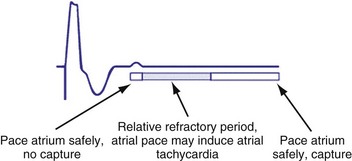
Figure 28-52 Noncompetitive atrial pacing algorithm.
(Redrawn from Medtronic Enpulse device manual.)
Managed Ventricular Pacing
Growing evidence in literature suggest right ventricular pacing is detrimental to hemodynamics in a number of patient populations, with many studies indicating an increased incidence of atrial fibrillation with ventricular pacing.45 A managed ventricular pacing (MVP) algorithm is designed to minimize unnecessary RV pacing. The MVP algorithm operates in an AAI(R) mode to minimize ventricular pacing; however, ventricular backup pacing is available if heart block occurs. Thus, some clinicians have described MVP as ADIR with mode switching to DDDR.46 Backup ventricular pacing occurs after any A-A interval occurs without a sensed ventricular event and is delivered at an interval equal to the A-A interval plus 80 msec. MVP automatically “mode switches” from AAI(R) to DDD(R) when no ventricular sensed event occurs in 2 of 4 preceding A-A intervals (multiple heart blocks occur in 4-beat window) (Fig. 28-54). MVP will maintain the dual-chamber DDD(R) mode for 1 minute and then performs an “AV conduction check.” The device monitors AV conduction by temporarily switching back to AAI(R) timing during one A-A cycle. The AV conduction check is scheduled at 2, 4, 8,… minutes, up to 16 hours after a transition to DDD(R) has occurred. If spontaneous R waves are sensed, the device will revert back to the AAI(R) operation (Fig. 28-55). Because cross-chamber blanking during AAIR pacing may affect sensing of ventricular arrhythmias, atrial pacing is inhibited during ventricular arrhythmia.46 Significant reduction of ventricular pacing has been demonstrated with the MVP algorithm. A dynamic ARP has been developed to avoid inappropriate switch to DDD(R) mode caused by nonconducted premature atrial ectopy or far-field R-wave oversensing. The net result of MVP is reduced frequency of ventricular pacing.45,47
In the MVP mode there may be undesirable lengthening of AV conduction with negative hemodynamic consequences.46 In one study, about 14% of patient had more than 40% AVIs longer than 300 msec. The hemodynamic significance of the A-V intervals in these patients is unknown.48 MVP may result in long V-V intervals and thus may lead to pause-dependent and pacing-facilitated ventricular proarrhythmia. Studies indicate, however, that this occurs no more than in other modes (e.g., DDDR).46
The AAIsafeR algorithm functions in the AAI mode with a conversion to DDD in the event of high-grade AV block.49,50 This algorithm uses a number of criteria to switch from atrial pacing to DDDR: (1) consecutive intrinsic A-V intervals greater than 350 to 450 msec, (2) “x out of y” A-A intervals without ventricular sensed event, (3) consecutive A-A intervals without ventricular sensed events, (4) pauses programmed at 2, 3, and 4 seconds, (5) ventricular sensed events within the ventricular safety pacing window after two consecutive atrial sensed events, and (6) 12 consecutive ventricular sensed events. After 100 DDDR cycles, the algorithm switches to AAI to assess for AV conduction. If more than three AAI-to-DDD switches occur on 3 consecutive days, or 15 or more in 1 day, the algorithm is disabled until reprogramming.46
Ventricular Rate Regularization
Because irregularity of ventricular rates during AF may be responsible for many AF symptoms, algorithms may attempt to pace in an effort to regularize the rhythm. These algorithms adjust the presence of pacing in response to the presence of ventricular sensed beats. Ventricular response pacing (VRP) and ventricular rate regulation (VRR) respond to sensed ventricular events (Fig. 28-56). If a ventricular sensed event occurs, the ventricular pacing rate is increased, and if a ventricular paced event occurs, the rate is decreased. Clinical studies show that variability in ventricular intervals in AF is greatly decreased (Fig. 28-57).
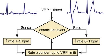
Figure 28-56 Ventricular response pacing (VRP).
(From Tse HF, Newman D, Ellenbogen KA, et al: Effects of ventricular rate regularization pacing on quality of life and symptoms in patients with atrial fibrillation. Atrial Fibrillation Symptoms Mediated by Pacing to Mean Rates (AF SYMPTOMS) study. Am J Cardiol 94:938-941, 2004.)
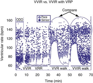
Figure 28-57 Ventricular response pacing (VRP).
(From Tse HF, Newman D, Ellenbogen KA, et al: Effects of ventricular rate regularization pacing on quality of life and symptoms in patients with atrial fibrillation. Atrial Fibrillation Symptoms Mediated by Pacing to Mean Rates (AF SYMPTOMS) study. Am J Cardiol 94:938-941, 2004.)
Timing Cycles in Other Dual-Chamber Modes
VDD Mode
The VDD mode offers both atrial and ventricular sensing with only ventricular pacing (Fig. 28-58). Tracking of atrial activity occurs similar to the DDD mode. When an atrial event is sensed, the AVI is initiated, and if a ventricular intrinsic event is not sensed by the end of the interval, a ventricular paced event is triggered. Sensing also occurs in the ventricle, which inhibits ventricular pacing. The VDD mode is not appropriate for individuals who have impaired sinus node function because there is no atrial pacing. This mode is mostly employed in pacemaker systems with a single lead that paces and senses the ventricle and that senses the atrium using a specially designed “floating” atrial electrode.
DDI Mode
Atrioventricular sequential pacing with dual-chamber sensing, non-P-synchronous, DDI mode provides sensing and pacing in the atrium and ventricle but does not track. When atrial events are sensed, atrial pacing is inhibited, but unlike the DDD mode, the AVI is not initiated (Fig. 28-59). Ventricular paced events following atrial sensed events will occur at the LRL rather than after the AV delay. Ventricular sensed events result in inhibition of ventricular pacing and reset the AEI. Absence of intrinsic atrial events or ventricular events by the end of the LRL results in pacing in the atrium and the ventricle, respectively. This mode is best suited for patients at risk for atrial tachyarrhythmias because there is no atrial tracking resulting in rapid ventricular pacing during atrial tachyarrhythmia. This mode can be useful when the mode-switching feature is unavailable or does not accurately function. In DDI mode the absence of tracking results in the inability of faster intrinsic sinus rates to be followed by ventricular paced beats as the sinus rates increase in response to greater metabolic demands with exertion and exercise. In addition, AV synchrony is lost when the intrinsic sinus rate exceeds the LRL, and AV conduction is absent or impaired. The use of DDIR pacing programmed so that sensor-driven pacing predominates will result in maintenance of AV synchrony.
Other Modes
In the DVI (AV sequential, ventricular inhibited) mode, which is the least used, the pacemaker will provide pacing in both atrium and ventricle (D), but only events in the ventricle (V) inhibit pacing. An atrial escape interval will be reset after a sensed or paced ventricular event, followed by an asynchronous atrial pacing output. However, a sensed spontaneous ventricular event within the AEI will inhibit and reset both atrial and ventricular pacing stimuli. The atrial pacing stimulus is followed by the A-V interval, and a spontaneous R wave will inhibit the ventricular output. The difference between DVI and DDI is that no atrial sensing is incorporated in the DVI mode, in which constant, competitive atrial pacing may occur (Fig. 28-60). The absence of atrial sensing may result in a paced atrial impulse immediately after an intrinsic atrial event, potentially triggering atrial tachyarrhythmia.
 Timing Cycles in Biventricular Pacing
Goals of Biventricular Pacing
The primary goal of bradycardia pacing is to achieve adequate heart rates to prevent symptoms and meet metabolic demands.51,52 To achieve this goal, bradycardia pacing timing cycles are designed to keep the heart rates from being too slow and to maintain appropriate AV synchrony.
Timing Cycles: Differences from Dual Chamber
Pacing Modes
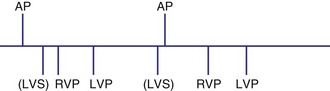
The timing cycles for BiV pacemakers are potentially complex, depending on which chamber(s) is sensed, which ventricle(s) is paced, the inter-ventricular delay, and the chamber(s) that resets the escape intervals.52–56 For most commercially available BiV devices, the sensing chamber(s) is usually the right ventricle and occasionally both ventricles (for older devices with Y connection). BiV pacing activates both ventricular chambers either simultaneously or sequentially (Fig. 28-61).
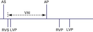
Atrioventricular Interval
For biventricular pacing to result in the desired hemodynamic effect, it is necessary for appropriately timed BiV paced beats to occur after paced or sensed atrial events.57 Therefore, AVI must be sufficiently short to ensure BiV capture and minimize fusion, yet long enough to allow adequate diastolic filling during the atrial contraction. Because the degree of native PR shortening during exercise may be significant, this may be a particularly challenging task. Similarly, programming an extremely short, fixed AV delay that applies to all rates and physiologic conditions is unlikely to be optimal, with ventricular depolarization and contraction occurring too early. In almost all cases, therefore, a form of rate-adaptive AV delay is used in CRT devices.
Several algorithms have been designed to maintain BiV pacing and activation. When a ventricular event is sensed on one pacing cycle, the A-V interval is shortened on the next timing cycle (AV hysteresis). If an atrial event is followed by a sensed right ventricular (RV) event, which is then followed by an LV paced event, on the next cycle, an RV paced event and an LV paced event may occur by shortening the time from the atrial sensed event to the RV paced event (Fig. 28-62). In addition, if the LV paced event occurs before the RV sensed event, it is possible to shorten the LV-RV timing on subsequent cycles (Fig. 28-63). However, such “negative” AV hysteresis function is often ineffective; permitting even one cycle with intrinsic conduction may have deleterious consequences. Perpetuation of native AV conduction and the absence of BiV pacing can result, as discussed later. If an intrinsic ventricular event is sensed within the A-V interval, one option might be to trigger a ventricular paced stimulus from the opposite ventricle, so-called ventricular sensed response. For example, if a sensed event is detected by the RV lead, an LV pacing output is delivered immediately to maximize LV capture and BiV activation (Fig. 28-64). However, it is unclear if the benefit of this strategy has limits, particularly with closely timed ventricular premature beats.
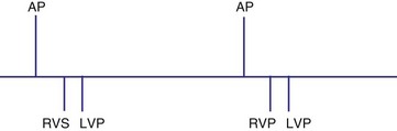
Figure 28-62 Biventricular pacing with RV sensed event before LV paced event.
(From Wang P, Kramer A, Estes NA 3rd, Hayes DL: Timing cycles for biventricular pacing. Pacing Clin Electrophysiol 25:62-75, 2002.)
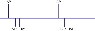
Figure 28-63 Biventricular pacing with LV paced event before RV sensed event.
(From Wang P, Kramer A, Estes NA 3rd, Hayes DL: Timing cycles for biventricular pacing. Pacing Clin Electrophysiol 25:62-75, 2002.)
Interventricular Timing Delay
Analogous to the A-V interval in atrioventricular delay, there may be delay between pacing in the right and left ventricles (interventricular delay). Several permutations of the relationship exist between the RV and LV timing based on the role of BiV or unipolar sensing. With RV sensing alone, which is predominantly the case in most current devices, the RV-LV interval may be positive, negative, or zero (Fig. 28-65) Several studies have demonstrated clinical or hemodynamic benefits of adjusting interventricular delay in patients who were classified as “nonresponders” to conventional CRT. Various echocardiographic Doppler parameters and timing intervals have been used to assess interventricular dyssynchrony, and tissue Doppler imaging (TDI) has been used to determine intraventricular dyssynchrony for V-V optimization. The introduction of delay raises several theoretical issues. As discussed further in the context of univentricular sensing and biventricular pacing, an interventricular delay may increase the risk of ventricular tachycardia from an unsensed, improperly timed ventricular depolarization.
Univentricular Sensing and Biventricular Pacing
Sensing may occur in one ventricle as it does in dual-chamber pacing. Usually, ventricular tachycardia is not a risk from competitive pacing. For example, if LV activation occurs before LV pacing, the LV pacing stimulus would unlikely be captured (Fig. 28-66). However, a set of circumstances may increase the risk of competitive pacing. For example, if the intrinsic LV-RV conduction time is long and a long RV-LV delay is programmed, several scenarios may result in a greater risk of competitive pacing. In one situation an LV sensed event occurs before RV and LV pacing occurs. Because there may be a considerable interval between the intrinsic LV event and the LV pacing stimulus, the left ventricle may no longer be refractory, resulting in LV stimulation at a short coupling interval (Fig. 28-67). In another example, an unsensed premature beat that originates in the left ventricle may be followed by an RV paced event and then an LV paced event. In such a case, the RV paced event occurred before conduction from the spontaneous LV PVC to the right ventricle.
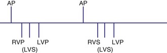
Figure 28-66 Right ventricular sensing only with positive RV-LV interval.
(From Wang P, Kramer A, Estes NA 3rd, Hayes DL: Timing cycles for biventricular pacing. Pacing Clin Electrophysiol 25:62-75, 2002.)
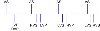
Biventricular Sensing and Biventricular Pacing
Various rules could be created to determine, for example, how both ventricles might be used for timing. These rules might depend on when the ventricular sensed event occurred. If the sensed event occurred in the A-V interval, as previously described, a new V-A interval and timing cycle might be created with no pacing (Fig. 28-68). A variation on this function might be to permit a ventricular paced event from the opposite ventricle to occur (Fig. 28-69). This could be immediately after the sensed ventricular event within the A-V interval (Fig. 28-70) or after the programmed RV-LV delay (Fig. 28-71). The V-A interval might be reset at the point of the RV sensed event within the A-V (see Fig. 28-69, A) interval or at the end of the programmed A-V interval (see Fig. 28-69, B). An RV sensed event will be followed by an LV paced event, probably after a modified interval. Also, after a ventricular sensed event in the A-V interval, it might be possible not to trigger a ventricular paced beat from the opposite chamber, and instead have an A-V interval “time-out” and the ventricular paced event occur at the end of the A-V interval. In BiV sensing and pacing, an LV sensed event in the AVI might result in an RV paced event at the end of the programmed AVI (Fig. 28-72). Alternatively, the LV sensed event in the AVI might trigger an RV paced event that would be used to reset the VA timing cycle (Fig. 28-73). Safety pacing with BiV pacing might be performed using either both ventricles or only one as backup pacing.
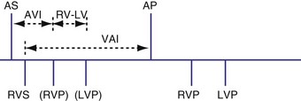
Figure 28-68 Right ventricular sensing only with inhibition of pacing.
(From Wang P, Kramer A, Estes NA 3rd, Hayes DL: Timing cycles for biventricular pacing. Pacing Clin Electrophysiol 25:62-75, 2002.)
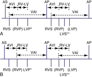
Figure 28-69 Biventricular sensing and pacing.
(From Wang P, Kramer A, Estes NA 3rd, Hayes DL: Timing cycles for biventricular pacing. Pacing Clin Electrophysiol 25:62-75, 2002.)
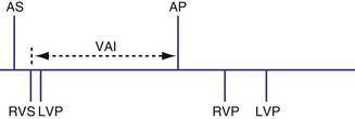
Figure 28-70 Biventricular sensing and pacing.
(From Wang P, Kramer A, Estes NA 3rd, Hayes DL: Timing cycles for biventricular pacing. Pacing Clin Electrophysiol 25:62-75, 2002.)
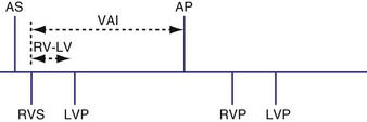
Figure 28-71 Biventricular sensing and pacing.
(From Wang P, Kramer A, Estes NA 3rd, Hayes DL: Timing cycles for biventricular pacing. Pacing Clin Electrophysiol 25:62-75, 2002.)
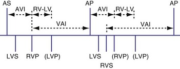
Figure 28-72 Biventricular sensing and pacing.
(From Wang P, Kramer A, Estes NA 3rd, Hayes DL: Timing cycles for biventricular pacing. Pacing Clin Electrophysiol 25:62-75, 2002.)
Figure 28-73 Biventricular sensing and pacing.
(From Wang P, Kramer A, Estes NA 3rd, Hayes DL: Timing cycles for biventricular pacing. Pacing Clin Electrophysiol 25:62-75, 2002.)
Biventricular Sensing with Univentricular Pacing
It is possible for a device to be programmed to have BiV sensing but only to pace from one ventricle, such as the left ventricle. In this case a sensed LV event might result in inhibition of LV pacing and resetting of the VA timing cycle (Fig. 28-74). If an RV sensed event occurred first, the LV paced event might be inhibited, resetting the timing cycle (Fig. 28-75), or might result in an LV paced event immediately, to minimize the delay after the RV sensed event (Fig. 28-76).
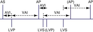
Figure 28-74 Biventricular sensing and unipolar pacing.
(From Wang P, Kramer A, Estes NA 3rd, Hayes DL: Timing cycles for biventricular pacing. Pacing Clin Electrophysiol 25:62-75, 2002.)
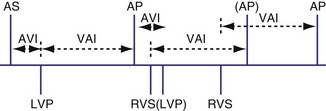
Figure 28-75 Biventricular sensing and unipolar pacing.
(From Wang P, Kramer A, Estes NA 3rd, Hayes DL: Timing cycles for biventricular pacing. Pacing Clin Electrophysiol 25:62-75, 2002.)
Loss of Biventricular Pacing
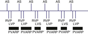
Because the hemodynamic consequences may be significant, it is important to identify possible causes of loss of BiV pacing.58 BiV pacing may be lost when A-V conduction becomes more rapid and the RV sensed event occurs within the A-V interval (Fig. 28-77). BiV pacing may be lost when the atrial rate increases so that the P wave falls within the PVARP of the preceding ventricular beat. This occurs when the atrial cycle length is equal to the sum of the PVARP and sensed A-V delay (TARP = AVI + PVARP) or above the maximum atrial tracking interval. The P wave will not be tracked, so conduction will occur. Because the resultant QRS complex will initiate a PVARP, the next P wave will fall within the PVARP. In this situation the programmed A-V interval is less than the intrinsic P-R interval, and thus the onset of loss of BiV pacing requires a faster atrial rate than the rate at which BiV pacing will be restored. BiV pacing will not be restored until the atrial cycle length is greater than the sum of the PVARP and the PR interval, called the intrinsic total atrial refractory period (ITARP). In patients with prolonged P-R interval, ITARP may be significantly longer than TARP. Once atrial undersensing in PVARP occurs during atrial tachycardia, loss of BiV pacing is perpetuated and may be restored only at much slower atrial rates. Restoration of BiV pacing will occur when the P wave following the last conducted QRS complex falls outside the PVARP. The relationship between atrial rate and loss of BiV pacing is shown diagrammatically in Figure 28-78. The ability to shorten the PVARP (indicated by PVARP’) may restore tracking of atrial sensed events and may restore BiV pacing (Fig. 28-79). Atrial premature beats with conduction may cause a similar phenomenon by causing atrial undersensing and loss of BiV pacing.59
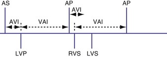
Figure 28-77 Biventricular pacing and sensing.
(From Wang P, Kramer A, Estes NA 3rd, Hayes DL: Timing cycles for biventricular pacing. Pacing Clin Electrophysiol 25:62-75, 2002.)
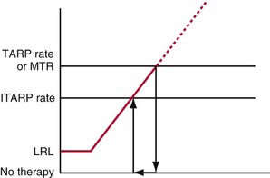
Figure 28-78 Relationship between atrial rate and presence of biventricular pacing.
(From Wang P, Kramer A, Estes NA 3rd, Hayes DL: Timing cycles for biventricular pacing. Pacing Clin Electrophysiol 25:62-75, 2002.)
Competitive Ventricular Pacing
Biventricular pacing as just described has introduced a new cause of competitive ventricular pacing. In this case, an LV stimulus follows LV activation, because LV sensed events are not used to inhibit ventricular pacing. For example, a conducted ventricular beat with a positive RV sense–LV sense interval caused by left bundle branch block may occur, followed by LV pacing before RV pacing because the left ventricle is no longer refractory, potentially inducing a ventricular arrhythmia (Fig. 28-80).
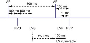
Figure 28-80 Biventricular pacing with RV-based timing and competitive pacing.
(From Wang P, Kramer A, Estes NA 3rd, Hayes DL: Timing cycles for biventricular pacing. Pacing Clin Electrophysiol 25:62-75, 2002.)
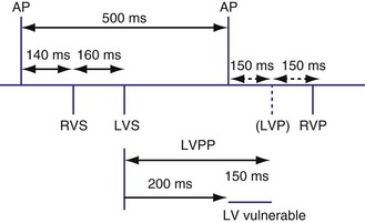
A feature called left ventricular pacing protection (LVPP) has been introduced to prevent LV competitive pacing. After an LV paced or sensed event has occurred, an LV paced event will not occur for the programmed LVPP (Fig. 28-81).
 Timing Cycles: Pacing Algorithms in Implantable Cardioverter-Defibrillators
Circumstances in which the maximum tracking rates and the sensor-driven rates are close to the ventricular tachycardia (VT) detection rate are most likely to result in abnormalities in arrhythmia detection. Examples of cases in which the pacing rates are likely to be particularly fast include sensor-driven pacing, tracking at or near the upper rate limit, rate smoothing, rate drop or sudden bradycardia response, ventricular rate regularization, and atrial pacing prevention algorithms. Abnormalities such as atrial oversensing with tracking in the DDD mode may lead to failure to detect VT. Cases of prolonged undersensing of VT have been reported during rate smoothing. Cooper et al.60 observed that VT remained undetected because the VT beats occurred within the ventricular blanking period after atrial paced events. Atrial pacing occurred because rate smoothing had been turned on. Such an interaction is promoted by a slow VT and rate-smoothing algorithm. Shivkumar et al.61 reported a similar case of failure to detect an episode of ventricular tachycardia. In a prospective study, Glikson et al.62 examined the role of rate smoothing in preventing VT detection. During ICD testing in 54 episodes of induced ventricular fibrillation/polymorphic VT, three episodes (5%) of minimal delay in detection were observed. However, in the 10 monomorphic VT episodes, four cases had absent detection and two had delayed detection. Based on these observations and simulator-based modifications of programmable parameters, the authors observed that long AV delay, high upper rate, and more aggressive rate smoothing increases the risk of VT underdetection. Figure 28-82 illustrates an example of VT that is underdetected because of rate-smoothing algorithm. A similar case has been described for the ventricular rate stabilization algorithm (Fig. 28-83).
Figure 28-82 Rate smoothing leading to AV pacing during ventricular tachycardia and resultant underdetection.
(From Glikson M, Beeman AL, Luria DM, et al: Impaired detection of ventricular tachyarrhythmias by a rate-smoothing algorithm in dual-chamber implantable defibrillators: intradevice interactions. J Cardiovasc Electrophysiol 13:312-318, 2002.)
Figure 28-83 Ventricular rate stabilization leading to pacing during ventricular tachycardia and resulting in underdetection.
(From Barold SS: Ventricular rate stabilization algorithm of ICD causing dual-chamber pacing during ventricular tachycardia. J Interv Card Electrophysiol 9:397-400, 2003.)
Rate smoothing has also been proposed as a mechanism for the prevention of VT by minimizing abrupt variations in cycle lengths in a short-long-short pattern. Wietholt et al.63 conducted the PREVENT study by randomizing patients in a 3-month crossover design to periods of rate smoothing versus no rate smoothing; 57 of the 153 patients (38%) had 358 VT episodes with rate smoothing off versus 145 episodes with rate smoothing on.
1 Barold SS. Modern concepts of cardiac pacing. Heart Lung. 1973;2:238-252.
2 Bernstein A, Daubert J, Fletcher R, et al. The revised NASPE/BPEG generic code for antibradycardia, adaptive-rate, and multisite pacing. Pacing Clin Electrophysiol. 2002;23:260-264.
3 Barold SS. Clinical significance of pacemaker refractory periods. Am J Cardiol. 1971;28:237-239.
4 Barold SS, Gaidula JJ. Pacemaker refractory periods. N Engl J Med. 1971;284:220-221.
5 Yokoyama M, Wada J, Barold SS. Transient early T wave sensing by implanted programmable demand pulse generator. Pacing Clin Electrophysiol. 1981;4:68-74.
6 Okreglicki A, Akiyama T, Ocampo C, Flynn D. Polarization potentials causing pacemaker oversensing. Jpn Circ J. 1998;62:868-870.
7 Paraskevaidis S, Mochlas S, Hadjimiltiadis S, Louridas G. Intermittent P wave sensing in a patient with DDD pacemaker. Pacing Clin Electrophysiol. 1999;22:689-690.
8 Frohlig G, Helwani Z, Kusch O, et al. Bipolar ventricular far-field signals in the atrium. Pacing Clin Electrophysiol. 1999;22:1604-1613.
9 Rosenheck S, Sharon Z, Leibowitz D. Artifacts recorded through failing bipolar polyurethane insulated permanent pacing leads. Europace. 2000;2:60-65.
10 Barold SS, Falkoff MD, Ong LS, Heinle RA. Oversensing by single-chamber pacemakers: mechanisms, diagnosis, and treatment. Cardiol Clin. 1985;3:565-585.
11 Tse HF, Lau CP. The current status of single-lead dual-chamber sensing and pacing. J Interv Card Electrophysiol. 1998;2:255-267.
12 Friedberg HD, Barold SS. On hysteresis in pacing. J Electrocardiol. 1973;6:1-2.
13 Barold SS. Prolonged atrioventricular block during AAI pacing for sick sinus syndrome. J Cardiovasc Electrophysiol. 2000;11:14-22.
14 Tripp IG, Armstrong GP, Stewart JT, et al. Atrial pacing should be used more frequently in sinus node disease. Pacing Clin Electrophysiol. 2005;28:291-294.
15 Barold SS, Falkoff MD, Ong LS, Heinle RA. Programmability in DDD pacing. Pacing Clin Electrophysiol. 1984;7:1159-1164.
16 Barold SS, Belott PH. Behavior of the ventricular triggering period of DDD pacemakers. Pacing Clin Electrophysiol. 1987;10:1237-1252.
17 Barold SS, Falkoff MD, Ong LS, Heinle RA. All dual-chamber pacemakers function in the DDD mode. Am Heart J. 1988;115:1353-1362.
18 Parravicini U, Mezzani A, Bielli M, et al. DDD pacing and interatrial conduction block: importance of optimal AV interval setting. Pacing Clin Electrophysiol. 2000;23:1448-1450.
19 Bode F, Wiegand U, Katus HA, Potratz J. Inhibition of ventricular stimulation in patients with dual chamber pacemakers and prolonged AV conduction [see comment]. Pacing Clin Electrophysiol. 1999;22:1425-1431.
20 Dennis MJ, Sparks PB. Pacemaker mediated tachycardia as a complication of the autointrinsic conduction search function [see comment]. Pacing Clin Electrophysiol. 2004;27:824-826.
21 Barold SS, Gallardo I, Sayad D. Wenckebach upper rate response of pacemakers implanted for nontraditional indications: the other side of the coin. Pacing Clin Electrophysiol. 2002;25:1283-1284.
22 Barold SS. Far-field R-wave sensing causing prolongation of the atrial escape interval of DDD pacemakers with atrial-based lower rate timing. Pacing Clin Electrophysiol. 2003;26:2188-2191.
23 Kusomoto F. Pacemaker timing cycles: ventricular based and atrial based. In: Al-Ahmad A, Ellenbogen K, Natale A, Wang PJ, editors. Pacemakers and implantable defibrillators: an expert’s manual. Minneapolis: Cardiotext, 2010.
24 Crossley GH, Pickett A. Miscellaneous pacing algorithms. In: Al-Ahmad A, Ellenbogen K, Natale A, Wang PJ, editors. Pacemakers and implantable defibrillators: an expert’s manual. Minneapolis: Cardiotext; 2010:158.
25 Lau CP, Leung SK, Tse HF, Barold SS. Automatic mode switching of implantable pacemakers. I. Principles of instrumentation, clinical, and hemodynamic considerations. Pacing Clin Electrophysiol. 2002;25:967-983.
26 Estes NA3rd. Atrial tachyarrhythmias detected by automatic mode switching: quo vadis? [comment]. J Cardiovasc Electrophysiol. 2004;15:778-779.
27 Israel CW. Analysis of mode switching algorithms in dual chamber pacemakers. Pacing Clin Electrophysiol. 2002;25:380-393.
28 Leung SK, Lau CP, Lam CT, et al. Is automatic mode switching effective for atrial arrhythmias occurring at different rates? A study of the efficacy of automatic mode and rate switching to simulated atrial arrhythmias by chest wall stimulation. Pacing Clin Electrophysiol. 2000;23:824-831.
29 Passman RS, Weinberg KM, Freher M, et al. Accuracy of mode switch algorithms for detection of atrial tachyarrhythmias [see comment]. J Cardiovasc Electrophysiol. 2004;15:773-777.
30 Wood MA, Ellenbogen KA, Dinsmoor D, et al. Influence of autothreshold sensing and sinus rate on mode switching algorithm behavior [see comment]. Pacing Clin Electrophysiol. 2000;23:1473-1478.
31 Walfridsson H, Aunes M, Capocci M, Edvardsson N. Sensing of atrial fibrillation by a dual chamber pacemaker: how should atrial sensing be programmed to ensure adequate mode shifting? Pacing Clin Electrophysiol. 2000;23:1089-1093.
32 Nowak B, Kracker S, Rippin G, et al. Effect of the atrial blanking time on the detection of atrial fibrillation in dual chamber pacing. Pacing Clin Electrophysiol. 2001;24:496-499.
33 Goethals M, Timmermans W, Geelen P, et al. Mode switching failure during atrial flutter: the “2:1 lock-in” phenomenon. Europace. 2003;5:95-102.
34 Simpson CS, Yee R, Lee JK, et al. Safety and feasibility of a novel rate-smoothed ventricular pacing algorithm for atrial fibrillation. Am Heart J. 2001;142:294-300.
35 Eguia LE, Pinski SL. Inactivation of a ventricular tachycardia preventive algorithm during automatic mode switching for atrial tachyarrhythmia. Pacing Clin Electrophysiol. 2001;24:252-253.
36 Barold SS, Mond HG. Fallback responses of dual chamber (DDD and DDDR) pacemakers: a proposed classification. Pacing Clin Electrophysiol. 1994;17:1160-1165.
37 Ward KJ, Willett JE, Bucknall C, et al. Atrial arrhythmia suppression by atrial overdrive pacing: pacemaker Holter assessment. Europace. 2001;3:108-114.
38 Blommaert D, Gonzalez M, Mucumbitsi J, et al. Effective prevention of atrial fibrillation by continuous atrial overdrive pacing after coronary artery bypass surgery [see comment]. J Am Coll Cardiol. 2000;35:1411-1415.
39 Levy T, Walker S, Rex S, Paul V. Does atrial overdrive pacing prevent paroxysmal atrial fibrillation in paced patients? Int J Cardiol. 2000;75:91-97.
40 Lam CT, Lau CP, Leung SK, et al. Efficacy and tolerability of continuous overdrive atrial pacing in atrial fibrillation. Europace. 2000;2:286-291.
41 Attuel P, Danilovic D, Konz KH, et al. Relationship between selected overdrive parameters and the therapeutic outcome and tolerance of atrial overdrive pacing. Pacing Clin Electrophysiol. 2003;26:257-263.
42 Israel CW, Gronefeld G, Ehrlich JR, et al. Prevention of immediate reinitiation of atrial tachyarrhythmias by high-rate overdrive pacing: results from a prospective randomized trial. J Cardiovasc Electrophysiol. 2003;14:954-959.
43 Hakala T, Valtola AJ, Turpeinen AK, et al. Right atrial overdrive pacing does not prevent atrial fibrillation after coronary artery bypass surgery. Europace. 2005;7:170-174.
44 Connolly SJ, Kerr CR, Gent M, et al. Effects of physiologic pacing versus ventricular pacing on the risk of stroke and death due to cardiovascular causes. Canadian Trial of Physiologic Pacing Investigators. N Engl J Med. 2002;342:1385-1391.
45 Sweeney MO, Bank AJ, Nsah E. Minimizing ventricular pacing to reduce atrial fibrillation in sinus-node disease. N Engl J Med. 2007;357:1000-1008.
46 Sweeney MO. Algorithms for minimizing right ventricular pacing. In: Al-Ahmad A, Ellenbogen K, Natale A, Wang PJ, editors. Pacemakers and implantable defibrillators: an expert’s manual. Minneapolis: Cardiotext; 2010:79-115.
47 Sweeney M, Ellenbogen K, Casavant D, et al. Multicenter, prospective, randomized safety and efficacy study of a new atrial-based managed ventricular pacing mode (MVP) in dual chamber ICDs. J Cardiovasc Electrophysiol. 2005;16:811-817.
48 Sweeney MO, Ellenbogen K, Tsang ASL, et al. Severe atrioventricular decoupling, uncoupling, and ventriculoatrial coupling during enhanced atrial pacing: Incidence, mechanisms and implications for minimizing right ventricular pacing in ICD patients. J Cardiovasc Electrophysiol. 2008;19:1175-1180.
49 Savoure A, Frohlig G, Galley D, et al. A new dual-chamber pacing mode to minimize ventricular pacing. Pacing Clin Electrophysiol. 2005;28(suppl 1):43-46.
50 Pioger G, Leny G, Nitzsche R, Ripart A. AAIsafeR limits ventricular pacing in unselected patients. Pacing Clin Electrophysiol. 2007;30:S66-S70.
51 Abraham WT. Cardiac resynchronization therapy for the management of chronic heart failure. Am Heart Hosp J. 2003;1:55-61.
52 Barold SS, Herweg B, Giudici M. Electrocardiographic follow-up of biventricular pacemakers. Ann Noninvas Electrocardiol. 2005;10:231-255.
53 Barold SS, Herweg B. Upper rate response of biventricular pacing devices. J Interv Card Electrophysiol. 2005;12:129-136.
54 Chang KC, Chen JY, Lin JJ, Hung JS. Unexpected loss of atrial tracking caused by interaction between temporary and permanent right ventricular leads during implantation of a biventricular pacemaker. Pacing Clin Electrophysiol. 2004;27:998-1001.
55 Akiyama M, Kaneko Y, Taniguchi Y, Kurabayashi M. Pacemaker syndrome associated with a biventricular pacing system. J Cardiovasc Electrophysiol. 2002;13:1061-1062.
56 Wang P, Kramer A, Estes NA3rd, Hayes DL. Timing cycles for biventricular pacing. Pacing Clin Electrophysiol. 2002;25:62-75.
57 Riedlbauchova L, Kautzner J, Fridl P. Influence of different atrioventricular and interventricular delays on cardiac output during cardiac resynchronization therapy. Pacing Clin Electrophysiol. 2005;28(suppl 1):19-23.
58 Taieb J, Benchaa T, Foltzer E, et al. Atrioventricular cross-talk in biventricular pacing: a potential cause of ventricular standstill. Pacing Clin Electrophysiol. 2002;25:929-935.
59 Lipchenca I, Garrigue S, Glikson M, et al. Inhibition of biventricular pacemakers by oversensing of far-field atrial depolarization. Pacing Clin Electrophysiol. 2002;25:365-367.
60 Cooper JM, Sauer WH, Verdino RJ. Absent ventricular tachycardia detection in a biventricular implantable cardioverter-defibrillator due to intradevice interaction with a rate smoothing pacing algorithm. Heart Rhythm. 2004;1:728-731.
61 Shivkumar K, Feliciano Z, Boyle NG, Wiener I. Intradevice interaction in a dual-chamber implantable cardioverter-defibrillator preventing ventricular tachyarrhythmia detection [see comment]. J Cardiovasc Electrophysiol. 2000;11:1285-1288.
62 Glikson M, Beeman AL, Luria DM, et al. Impaired detection of ventricular tachyarrhythmias by a rate-smoothing algorithm in dual-chamber implantable defibrillators: intradevice interactions. J Cardiovasc Electrophysiol. 2002;13:312-318.
63 Wietholt D, Kuehlkamp V, Meisel E, et al. Prevention of sustained ventricular tachyarrhythmias in patients with implantable cardioverter-defibrillators: the PREVENT study. J Interv Card Electrophysiol. 2003;9:383-389.