[level-membership-for-orthopaedics-category]
CHAPTER 71 Thoracolumbar Instrumentation
Anterior and Posterior
Overview and History
Internal fixation of the thoracolumbar spine has been used for the past century.1 Many of the implants were developed in different parts of the world because they were designed to treat various spinal conditions in specific populations. For example, the “Hong Kong procedure” gave rise to modern anterior thoracolumbar surgery in an effort to treat the deformity associated with spinal tuberculosis.2 In other cases, the concepts behind new spinal implants were borrowed from other fields. The CHARITÉ artificial disc replacement arose from total knee arthroplasty designs with a low-friction design. Kyphoplasty to treat painful osteoporotic fractures evolved from angioplasty balloons.3,4
There has been a surge of new implants and spinal technology. The spine surgeon needs to understand and consider the U.S. Food and Drug Administration (FDA) status of each implant. Although the FDA may not dictate or interfere with medical care, medical devices are placed into one of three categories by the FDA (Tables 71-1 and 71-2). Off-label use of thoracolumbar instrumentation occurs in two settings, each of which involves different demands on the physician. First, the common practice of using a device for an indication other than that for which it was assessed by the FDA is termed practice of medicine. The second off-label use involves experimental or investigational devices (e.g., nuclear replacements).
| I. Neither Standard nor Premarket Approval Warranted |
TABLE 71–2 Types of Thoracolumbar Spine Instrumentation
| Type | FDA Status* |
|---|---|
| Anterior Instrumentation | |
| Anterior plates | |
| Rigid systems | A |
| Semirigid system | A |
| ALIF graft containment systems | I |
| Anterior cages | |
| Threaded interbody cages | A† |
| Vertical mesh cages‡ | A |
| Rectangular cages‡ | |
| Lumbar disc arthroplasty systems | |
| Posterior Instrumentation | |
| Wiring systems | A |
| Luque wiring | |
| Drummond/Wisconsin wiring | |
| Hook-based systems | |
| Pedicle, transverse process, laminar | |
| Segmental or nonsegmental | |
| Pedicle screw systems | |
| Plating systems | A§ |
| Rod-based systems | A |
| Monoaxial | A |
| Polyaxial | A |
| Dynamic rodding | I |
| Translaminar facet screws | A |
ALIF, anterior lumbar interbody fusion
* FDA status refers to the most common use of the device as described in the chapter text. Virtually all of these devices have FDA-approved uses. The status of these devices is constantly evolving. A, approved; I, investigational; O, off-label.
† Many cages commonly used for interbody fusions are approved as corpectomy spacers only.
‡ Many of these cage systems are available in allograft bone, polyetheretherketone, and titanium versions.
§ There are limitations for FDA class II labeling of pedicle screws (see text).
With the rapid change in available systems, a full understanding of FDA status becomes more important and ever more difficult. Some systems developed and described for one use are FDA-approved for another indication. An example is the Dynesys system (Zimmer Spine, Minneapolis, MN), which has been presented at meetings as a means of restoring lumbar stability without fusion. For FDA purposes, Dynesys is a typical class II fusion pedicle screw system for lumbar fusion. It is unreliable to depend on a textbook or sales representative for this up-to-date information. Instead, it is prudent to review the FDA’s website (www.fda.gov) and review the product labeling.
Other efforts at spine stabilization without fusion should be mentioned. For young children with spinal deformity, numerous implant systems seek to limit curve progression without arresting axial spine growth. Physeal staples, which may be inserted thoracoscopically, are being used to halt growth selectively on the convex side of the deformity.5 A vertical expandable prosthetic titanium rib (VEPTR; Synthes Spine, West Chester, PA) provides an internal, nonrigid brace for spinal or thoracic cage deformity to allow further thoracic cage growth.6 More traditionally, “growing rods” have been employed to provide temporary, internal bracing of rapidly progressive curves in young children and to allow additional axial growth before a formal fusion is performed.7 In an effort to prevent long-term pulmonary restriction, these modalities seek to allow maximal chest cavity development.
Relevant Anatomy
Bony Anatomy
The thoracolumbar spine is divided into five regions: the cervicothoracic junction, the mid-thoracic spine, the thoracolumbar junction, the mid-lumbar spine, and the lumbosacral junction. Each region has distinct anatomic and biomechanical characteristics that must be considered when planning reconstructive and instrumentation surgery. The anatomy typically serves the biomechanics. For example, facet orientation predicts motion segment direction and range of motion. Facet orientation also “couples” motion so that flexion necessitates translation.7
Placement of a thoracolumbar implant affects the spinal ligaments directly or indirectly. Direct anterior lumbar interbody approaches require sacrifice of the anterior longitudinal ligament. In disc replacement procedures, to achieve more parallel distraction, the posterior longitudinal ligament may need to be resected. The long-term effect of such ligamentous resection on motion preservation kinematics is unknown.8
The thoracic spine can be divided into two subregions: the upper thoracic spine to T8 and lower thoracic spine (T8-thoracolumbar junction). The articulation of the thoracic spine with the rib cage makes the thoracic spine the most rigid portion of the spine. Extending the three-column concept of Denis, an intact rib cage and sternum complex functions as a mechanical fourth column, preventing flexion and extension above T9.9
The upper thoracic spine allows significant segmental rotation (10 degrees). Below T8-9, the major plane of motion is flexion and extension.9 Before proceeding with a transthoracic approach and spinal reconstruction, the surgeon must be familiar with the articulations between the rib and vertebral body. There are two sets of demifacets: one at the disc level and the other at the transverse process. Radiate ligaments stabilize the articulation further. The rib attaches to the transverse process and the superior aspect of the same-number vertebra (at the level of the pedicle). For example, to reach the T9-10 disc, one can follow the T10 rib to the superior aspect of the T10 body.
The rib–pedicle–transverse process junction is critical in posterior approaches as well. Because the pedicles of the mid-thoracic spine are quite narrow, some authors have recommended an in-out-in approach for pedicle screw insertion. With this technique, the pedicle screw trajectory begins dorsally, but as the pedicle narrows, the screw passes laterally into the space between the rib and the pedicle. In this space, it contains only ligamentous tissues, and penetration does not jeopardize neurologic structures or the lung parenchyma.10
Neurovascular Anatomy
A primary goal of thoracolumbar instrumentation is to prevent neurologic injury and protect the neural elements. It is crucial to understand the anatomy. The spinal cord typically ends at the L1-2 disc space. Below the conus, the nerve roots pass from the central thecal sac through the neuroforamen into the pelvis. Several cadaveric and imaging studies have described the relationship of the bony elements and their proximity to the neural structures. One cadaveric study measured the average distance from lumbar pedicle to the dural sac medially. From cranial to caudal in the lumbar canal, the range was 1.29 to 1.56 mm; clinically, this means that a medical pedicle breach greater than 1.29 mm has a significant chance of contacting or injuring the dura (Fig. 71–1).The pedicle is farther from the superior nerve root at 4.12 to 5.52 mm but closer to the inferior root, where distances ranged from 1.10 to 1.06 mm. The nerve roots and dura are statistically further from the L5 pedicle than from other pedicles, making the L5 pedicle safer than other lumbar pedicles for screw insertion.
When approaching the upper thoracic spine anteriorly, the approach is typically from the right to avoid the arch of the aorta. Scoliotic curves are typically approached from the convexity of curve, allowing a more complete release. The lumbar spine is typically approached from the left for several reasons. First, the liver is on the right and is more difficult to mobilize. Second, a left-sided approach brings the surgeon into contact with the aorta before the vena cava. The aorta is more easily recognized and is more durable, so the risk of sudden, catastrophic blood loss is less in the event of a vascular injury. With the advent of lumbar disc arthroplasty and anterior lumbar interbody fusion (ALIF), which require an anterior approach, the aorta, inferior vena cava (IVC), and iliac vessels are at risk for potential injury. Magnetic resonance imaging (MRI) is vital for preoperative evaluation of the vascular structures and for detecting potential vascular anomalies. Exposure of the L4-5 disc space requires retraction of the aorta and IVC from left to right. To mobilize these structures, the iliolumbar vein must be identified and ligated. When exposing the L5-S1 disc space, the middle sacral artery and vein must be ligated, and the left common iliac vein is elevated superiorly and laterally. When considering exposure to the lower lumbar spine, vascular calcifications in an older patient may limit retraction of the vessels and may be a contraindication to anterior surgery. In addition, any patient with previous abdominal or hernia surgery must be carefully evaluated because scar tissue may be a contraindication to abdominal surgery (Fig. 71–2).
When performing posterior thoracolumbar surgery, it is crucial to be cognizant of the anterior vascular anatomy. The heart-shaped thoracic vertebral bodies can allow passage of thoracic pedicle screws out of their respective bodies and place the aorta at risk for injury. One study measured the average distance from the aortic wall to the vertebral body cortex at the apex of the curve by MRI and found it was greater in patients with scoliosis (4.0 mm) than in a normal group (2.5 mm) (P < .05). The distance from the posterior aspect of the aorta to the anterior aspect of the spinal canal was less in the scoliosis group (11.1 mm) than in the normal group (19.2 mm) at T5-12 (P < .05). The aorta was positioned more laterally and posteriorly at the T5-12 vertebral bodies in these patients.11 When placing pedicle screws, preoperative planning is essential to determine the appropriate screw length to minimize the risk of vascular injury. Typically, pedicle screws on the left side place the aorta at more risk of injury, and slightly shorter screws should be placed.
Biomechanics of Thoracolumbar Instrumentation
Understanding disease state pathomechanics and implant biomechanics is crucial to successful construct design. Occasionally, implants fail because they are misplaced. Instrumentation more commonly fails owing to a judgment error, however (Table 71–3). Typically, the surgeon fails to understand fully one or more of the following seven factors:
TABLE 71–3 Important Factors in the Selection of Thoracolumbar Implants
Important Factors in the Selection of Lumbar Implants
The following are important factors to keep in mind when selecting lumbar implants:
Basic Biomechanical Principles
A ductile material allows permanent deformation before failure. Ductile materials include metals such as steel and titanium. Brittle materials, such as adult cortical bone and polymethyl methacrylate (PMMA), can fail without deformation. Another mechanical concept that relates to the effect of degenerative change on segmental motion is the neutral zone. Within the neutral zone, the spine offers minimal resistance to motion. Minor changes in load can lead to major shifts in position; for example, a patient with disc damage may exhibit an increase in the neutral zone, allowing motion to occur beyond the pain-free zone under physiologic loads while showing no change in the spine’s overall range of motion. Operative stabilization may decrease pain by decreasing the neutral zone but typically also decreases ultimate segmental range of motion.12,13
Implant Materials and Corrosion
Two types of titanium are typically used. Pure titanium is recommended only when very low strength is needed because it has a low yield strength of only 170 to 485 MPa. More typically, a titanium-aluminum-vanadium alloy, with yield strength of 800 MPa, is employed; its greater strength does not change the favorable modulus of pure titanium (110 GPa).14 Ultimate tensile strength—the maximum stress a material can sustain without changing shape—may be altered during surgery. Titanium rods are particularly sensitive to notching.15 If a complex rod contour is required, a template should be employed to minimize the amount of rod bending. In some patients with rigid dual curve deformities, it may be more effective to use separate rods in the thoracic and lumbar spine, employing rod-to-rod connectors (“dominoes”) to complete the construct.
In a biologic environment, fretting and corrosion can occur between the modular components of a spine construct. Kirkpatrick and colleagues subjected 48 spinal implant constructs to surface analysis stereomicroscopy.16 Titanium alloy implants (n = 25) showed no significant corrosion, but three of the constructs showed fatigue failure of the anchoring screws. The cobalt alloy construct showed no evidence of corrosion. Semirigid stainless steel implants had mild surface alteration, whereas rigid constructs showed moderate to severe corrosion. Based on their findings, the authors recommended avoiding rigid stainless steel implants or constructs with different surface finishes between rods and connectors. The surgeon must use caution when combining implants made of different metals. Mixing stainless steel with titanium would lead to a galvanic response and early corrosion, although titanium has been used with cobalt-chromium alloy without significant corrosion or complications.
Increasingly, nonmetallic implant materials have been used in thoracolumbar implants. Typically, these materials are used as cages, spacers, and graft containment systems rather than as fixation systems. Advantages of radiolucent materials such as PEEK include easier radiographic assessment of graft integration. For some nonmetallic implants, the modulus of elasticity is closer to that of host bone, allowing greater load sharing. Mechanical testing showed acceptable mechanical and fatigue characteristics for PEEK as a load-bearing implant material.16
The material properties of implants are also affected by manufacturing variables, such as drill holes, structural imperfections, and surface irregularities. Implant fatigue is an important cause of failure. The average spine cycles 3 million times per year.17–19 Because current implants are overengineered for their designated function, implant failure is more likely to occur from improper selection than from mechanical properties. If bone healing is delayed or incomplete, the implant or construct ultimately fails, so meticulous attention to bone grafting technique is imperative.
Fusion
Two important goals in designing an appropriate spinal construct are to provide spinal stability and to facilitate healing. The trend away from autogenous graft to allograft generally lengthens the duration of bone healing. Numerous animal models have shown that instrumentation increases the rate of fusion maturation.20 A delay in fusion may increase the risk of implant failure or the propensity for collapse of structural grafts.21 Use of bone morphogenetic protein generally accelerates healing and may permit use of less fatigue-resistant constructs.
When clinical or mechanical circumstances increase the risk of pseudarthrosis, additional steps, such as addition of L5-S1 interbody fusion below a long posterolateral fusion, should be considered.22 Along the same lines, the anticipation of increased postoperative loading, poor patient compliance, or inadequate postoperative immobilization may warrant more rigid forms of operative stabilization. Examples include patients with neurologic or motion disorders who are subject to increased spinal loads and patients with spinal cord injury or a colostomy for whom brace immobilization is impractical.
Historically, the most common fusion technique was the posterior fusion. The primary advantage of this approach was easy surgical access to the midline posterior elements (spinous processes and lamina). Disadvantages included its limited utility in laminectomy patients. Also, the graft material lies distant from the center of rotation and experiences significant tensile forces with spine flexion. This distance increases tensile stress and motion on the graft that could lead to migration, excessive motion, or graft resorption and ultimate nonunion.23 The most common contemporary fusion procedure is the intertransverse (posterolateral) fusion in which the facet joints, lateral pars, and transverse processes are decorticated and grafted, leaving the lamina accessible for decompression. In an intertransverse fusion, the graft material is placed closer to the center of vertebral rotation.24 The disadvantage is a poor vascular bed and a decreased area for fusion.
Interbody fusion provides significant mechanical advantages in terms of graft compression and a large, well-vascularized fusion surface. The anterior column fusion spans the neutral zone and, when healed, represents the strongest mechanical block to segmental motion.23,25 Even a solid intertransverse fusion may fracture or elongate if excessive or repeated load is placed across the motion segment.24
Thoracolumbar implants share applied loads with the spine until a stable fusion occurs. If a construct bears most of the load, stress shielding of the spine results and may lead to device-related osteopenia.26 The clinical sequelae of this shielding include graft resorption and possible implant failure. Increased emphasis has been placed on load-sharing implants in recent years.
Implications of Osteoporosis
Osteoporosis is the most common metabolic bone disorder and results from loss of the crystalline (inorganic) and collagenous (organic) portions of bone. Throughout life, the body constantly remodels bone by removing old bone and creating new bone. Although the pathomechanics are incompletely understood, osteoporosis occurs when the rate of bone resorption exceeds the rate of bone formation. Lower rates of bone formation result in a decline in overall mineral density of bone. Unbalanced osteoclast activity results in disruption of the normal connectivity between bony trabeculae. Bone can be weakened in the material and architectural sense.27 There are an estimated 40 million people at risk for osteoporosis in North America. With the aging of the population, this estimated number is likely to triple over the next 3 decades. Management of spinal disorders in an osteoporotic spine will be a significant problem in the future.28 Thoracolumbar instrumentation options in patients with osteoporosis are limited because implant failure in osteoporotic bone is common. Even if healing occurs uneventfully, patients with osteoporosis are at risk for compression fractures and spondylolisthesis adjacent to rigid constructs.29,30
For many patients, the diagnosis of osteoporosis and initiation of appropriate management is delayed. Because the consequences of failure to recognize osteoporosis are so high, it is incumbent on the spine surgeon to screen at-risk patients.31 There are three main types of osteoporosis: type I (postmenopausal), type II (senile), and type III (secondary). Type I affects the trabecular bone of women, more than men, in their 6th and 7th decades. Type II osteoporosis arises in the 8th and 9th decades and increasingly affects the cortical bone of men and women equally. Although categorizing a thin, elderly, white, or Asian woman at risk for osteoporosis may be relatively straightforward, younger and larger patients are increasingly at risk for secondary (type III) osteoporosis. Excessive endogenous or exogenous cortisol is deleterious to bone mass and is a cause of secondary osteoporosis. Long-term use of thyroid replacement drugs, blood thinners, and various seizure medications may also result in osteoporosis, and patients taking these medications should undergo screening before major spinal reconstruction. At least 30% bone mass loss is needed to identify osteopenia reliably on plain radiographs. Dual-energy x-ray absorptiometry (DEXA) is a much better screening tool than plain radiography.32 Results of DEXA scans are given in T and Z scores. The T score compares the patient’s bone mineral density (BMD) with mean values for healthy, same-gender young adults. For each standard deviation below the norm, fracture risk increases 1.5-fold to 3-fold. A T score of −1 implies a 30% chance of fracture. As the T score decreases from −1 to −2, the risk of instrumentation failure increases significantly. The Z score compares BMD with age-matched controls. A Z score less than −1.5 warrants a more extensive workup for osteomalacia or neoplasm. DEXA values are falsely increased with scoliosis, compression fractures, spondylosis, extraosseous calcification, and vascular disease. In many spine patients, the T score at the hip may be more accurate than the spine value.
Depending on the patient’s activity level, the nature of the intended surgery, and the severity of the osteoporosis, preoperative initiation of antiosteoporotic management and delay of elective spine procedures until follow-up DEXA scores improve may be warranted.33 Calcitonin, via subcutaneous injection or nasal spray, decreases osteoclastic bone resorption. Over the short-term, calcitonin also enhances bone formation, leading to a slight net bone accretion. Over the long-term, osteoblastic activity slows, however, and bone mass stabilizes. That is, after several years, calcitonin is no longer effective.34 Bisphosphonates dramatically suppress bone resorption and decrease hip and spine fractures. These agents directly stabilize the bone crystal, making it more resistant to osteoclastic bone resorption. They also inhibit osteoclast activity. Bisphosphonates preserve bone architecture and overall density. Weekly and monthly dosing of these agents improves compliance with no increase in toxicity. Most patients with osteoporosis should be receiving a bisphosphonate. For patients who cannot tolerate or have not responded to bisphosphonates and for patients with severe osteoporosis and major spinal instability, more aggressive antiosteoporotic management in the form of pulsed parathyroid hormone administration should be considered. Parathyroid hormone (Fortéo) is anabolic to bone and leads to early, dramatic increases in bone mass.35
When planning a spinal reconstruction procedure in an at-risk patient, it is important to recognize areas of the spine that are vulnerable to the ravages of osteoporosis. Trabecular bone represents 20% of the total bone mass and is found in the metaphyses and epiphyses of long bones and in the cuboid bones (including the vertebrae). Because trabecular bone exhibits eight times greater metabolic activity than cortical bone, the mechanical impact of osteoporosis affects trabecular bone earlier and to a greater degree than cortical bone (Fig. 71–3).27,36 It was reported in a more recent article that threshold BMD for successful use of anterior spinal instrumentation was 0.22 g/cm (as measured by quantitative computed tomography [CT]).37 Often, combined anterior and posterior surgeries with multiple, additional fixation points are required to achieve adequate fixation.37,38
Other strategies to improve the stability of fixation in an osteoporotic spine include augmentation of screw tracts with PMMA, use of laminar hooks to “protect” inferior pedicle screws, expanding screw designs,39 triangulated screw placement, increased use of transverse connectors, and bicortical vertebral body purchase. BMD is linearly related to screw insertion torque and pullout strength.40 The surgeon’s tactile sense of purchase when placing the screw relates to construct strength.40 PMMA may be added to screw tracts to increase pullout strength significantly, or bicortical purchase may be sought.40,41 Overall, BMD has a greater impact than unicortical purchase on screw pullout strength.42,43 Improved unicortical screw strength can be achieved with triangulated and subchondral placement.44,45 If bilateral screws are placed in a triangulated pattern, use of a transverse or cross connector further increases fixation strength. Mechanically, stability is improved by the presence of bone between the screws rather than merely by the bone within the threads of each screw individually.44 Bicortical screw placement may involve additional surgical risk, although it improves holding power and improves the construct’s resistance to cyclic loading. Bicortical purchase with posterior cortical pedicle screws offers less strength than anteriorly placed vertebral cancellous screws.46,47 Posteriorly and anteriorly placed screws benefit from purchase into the stronger subchondral bone just below the endplate, but the effect is more pronounced anteriorly.47 Bicortical purchase is typically not recommended for thoracolumbar pedicle screws because of risk of injury to anterior vascular structures. For sacral screws, especially in long constructs, bicortical screws improve holding power and sagittal plane correction.48,49 Some authors have recommended aiming the screw upward into the disc space or through the sacral promontory.50,51
With particular clinical challenges, such as osteoporosis, changing specific aspects of the implants themselves may improve fixation. In patients with osteoporosis in particular, maximizing pedicle screw diameter improves pullout strength and decreases the risk of fatigue failure of the screw.48 Screw length is linearly related to pullout strength. Little difference is seen between self-drilling or self-tapping designs43; if tapping is performed, undertapping by 1 mm leads to greater pullout strength than undertapping by 0.5 mm.48 In many cases, the angle of implantation is as important as the implant characteristics themselves. In anterior and posterior constructs, one should seek to avoid parallelogram constructs in which the screws and longitudinal members form a perfect square or rectangle. These constructs resist lateral loads less well than a triangulated pedicle screw construct.52 In anterior dual-rod constructs, a trapezoidal short-short/long-long construct is used.
Anatomic Model of Understanding Thoracolumbar Instrumentation
Modern, posterior, rigid, segmental spine stabilization systems arose in response to kyphoscoliosis deformity occurring in patients surviving polio and tuberculosis.53 Internal stabilization began in the early 1900s by Lange, but it was not until the 1950s and 1960s that Harrington, Moe, and others developed the first generation of modern spinal instrumentation.54 In the 1980s, Cotrel and Dubousset first popularized rigid, segmental hook-based fixation.53 At the present time, rigid, segmental, posterior transpedicular constructs represent the most common form of thoracolumbar instrumentation. Despite the dominance and versatility of transpedicular constructs, instrumentation failure is by no means rare. Appropriate use of these implants requires an understanding of their mechanical properties and the properties of alternative devices. Increasingly, these alternatives include “dynamic” or “motion-preserving” constructs.
Posterior Approach
The midline posterior approach is the most common approach for placement of thoracolumbar instrumentation. This extensile approach is applicable from the occiput to the sacrum. Below L2-3, the level of the conus medullaris, the dural sac may be safely retracted to afford enough exposure to the posterior disc space for performance of a posterior lumbar interbody fusion. In the upper lumbar spine, the risk of neural injury with dural retraction increases, and more oblique approaches to the disc space, such as transforaminal lumbar interbody fusion, are safer. In the thoracic spine, a midline posterior approach is considered dangerous for decompression of anterior compressive pathology (Fig. 71–4).
The powerful retractor systems available for posterior instrumentation procedures create extremely high levels of intramuscular pressure. Over time, this pressure can cause muscle necrosis similar to a compartment syndrome. For longer cases, the retractors should be removed every 2 hours to allow muscle recovery.33,34 This recovery time is particularly important because preoperative muscle abnormalities may exist in some conditions, which can be accentuated by the trauma of extended muscle retraction. One study found that preoperative paravertebral muscle biopsy specimens in 30 patients with spondylolisthesis were histologically different compared with normal controls.35 Most thoracolumbar instrumentation requires a relatively wide exposure beyond the facet and out into the transverse process.
The lateral extracavitary or costotransversectomy approach allows access to thoracic vertebral bodies from a posterior approach without violation of the pleura or takedown of the diaphragm.36 Visualization is reduced, however, compared with visualization for a corpectomy. Significantly more bone resection (including the rib, costotransverse joint, facets, and pedicle) is required to achieve that visualization.36,37 Costotransversectomy is associated with increased blood loss, longer operative time, increased paraspinal muscle disruption, and chest wall numbness from intercostal nerve resection. Occasionally, anterolateral cord compression can be addressed with a compromise approach between a standard laminectomy and a formal costotransversectomy. These transpedicular decompressions are known by various names, such as pediculofacetectomy, and are particularly useful in patients with tumors in whom the neoplasm has already destroyed most of the pedicle.38 In this case, the decompression is mainly soft tissue removal, and the anterior compressive elements can be removed indirectly by pulling them away. Although this approach confers limited visualization, it reduces operative time, blood loss, and iatrogenic destabilization.39,40 Visualization can be improved with a 70-degree endoscope.41
In the lumbar spine, the Wiltse paramedian approach, although described for resection of far-lateral disc herniations, has been used for interbody and posterolateral fusions. A bilateral paramedian approach is best when no midline decompression is needed. Additionally, this approach could be considered for posterolateral pseudarthrosis revision to avoid midline scar. A Wiltse paramedian type of approach is used in most minimally invasive surgical fusions employing tubular retractors, microscopic dissection, and fluoroscopic guidance. Iatrogenic muscle injury can result from denervation of the primary motor branch of the dorsal primary ramus when the muscle is stripped from the midline beyond the facets.43 Many studies have examined the effects of muscle splitting versus subperiosteal dissection on postoperative muscle health. One MRI study compared muscle enhancement after tubular discectomy versus a standard open discectomy. This study failed to show that microendoscopic discectomy produced less paravertebral muscle disruption than a traditional approach.44
Facet-Based Approaches
Numerous methods of facet fixation have been proposed. Historically, small screws were placed directly through the facet joint. Although these screws were able to lock the facets, their short length produced too small a lever arm to counteract the forces to which the lumbar facet is exposed, and many of these implants failed. Techniques at the present time are exploring additional methods of bony purchase. The most common of these is the Magerl technique, in which 4.5-mm, fully threaded cortical screws, usually 50 to 60 mm in length, are passed from the opposite side of the spinous process through the ipsilateral lamina and across the facet.55 The Boucher technique is similar but incorporates a greater degree of pedicle penetration.56 In both of these techniques, the screws are not placed in lag mode. In addition, they do not provide the strength that the three-column purchase of transpedicular instrumentation affords. These techniques are indicated for one-level or two-level fixation when reduction is not needed.
These translaminar facet screws are often used as posterior column extension supports for anterior lumbar interbody fusion procedures. The advantages of these screws include minimally invasive insertion via a 4-cm percutaneous approach. Translaminar facet screws are much less expensive than transpedicular constructs and offer less impingement on surrounding musculature. Disadvantages include the need for postoperative immobilization, which delays rehabilitation. Contraindications to translaminar facet screws include absence of adequate lamina or facet joints. These screws may be placed after laminotomy procedures but not typically after full laminectomy. Given that these screws are less rigid than transpedicular instrumentation, they are probably best reserved for slim, low-demand, compliant patients with intact laminae and facet joints.55
Laminar Wires and Hooks
Traditionally, posterior thoracolumbar instrumentation has been divided into rigid and nonrigid implants. The earliest constructs incorporated the spinous processes or other posterior elements alone or with slabs of structural iliac crest autograft. Although simple wiring techniques are no longer used in the thoracolumbar spine, many wire-rod techniques continue to be routinely employed. The most common technique—Luque wiring—employs sublaminar wires as anchors. These wires are wrapped around rods to form a segmental, nonrigid spine construct. Such techniques are nonrigid because they allow “pistoning” of the spine in a craniocaudal direction. Luque’s construct was the first segmental system that used multiple wire attachment points.53,57 In North America today, Luque constructs are preferentially used in the thoracic spine. Common indications include neuromuscular scoliosis, scoliosis with thoracic lordosis, and occasional cases of idiopathic scoliosis. Hybrid constructs using Luque wires with pedicle screws and other bone anchors are more commonly used. Contraindications to sublaminar fixation include absence of laminae. In addition, there is a danger of passing the wire through the spinal canal, particularly in patients with kyphosis or canal stenosis.58 Because wiring techniques do not provide axial stability, they are a poor choice for stabilization of pathologic processes with anterior column insufficiency. For example, sublaminar wires should not be used as primary fixation in patients with vertebral fractures or tumors.
In response to the risk of sublaminar wire passage, Drummond proposed a technique, commonly referred to as the Wisconsin method, in which the rod is wired to the spinous processes.59 This method has been used with Harrington rods and other rod systems to provide additional stability by segmental fixation.60,61 A button may be used to decrease wire cut-through of the spinous process. Although this technique is rarely used alone anymore, it may be useful in hybrid constructs, particularly when limitations of bony anatomy or breakout of prior instrumentation renders the pedicles and other posterior elements unusable.
Disadvantages of this construct, as with rigid implants elsewhere, included the effect of fusion on adjacent segments. In contrast to pedicle screw constructs, which employ the concept of three-column spine fixation, hooks anchor to the posterior elements alone and do not have the same power to reduce scoliosis.62 Although misplaced pedicle screws can produce catastrophic neurologic or vascular injury, hooks by their very nature are canal intrusive. Mildly misplaced screws produce less canal encroachment than hooks. Polly and colleagues63 have published an analysis of the volumetric effects of hook placement on the spinal canal.
In a comparison of pullout strength, thoracic pedicle screws were found to be significantly stronger than hooks and were recommended for rigid curves.64 In terms of operative time, one study showed no difference between the operative time or correction achieved with hook or screw consults.65 Finally, the pullout strength of hooks seems less sensitive to osteoporosis than screws, although screws are still stronger than hooks.66
Various hooks with different characteristics are available. Each of these is suited to a particular mode of placement and loading. Pedicle hooks, resting on the lamina of the instrumented vertebra and the superior articular process of the next distal vertebra, are the strongest. They are always directed cephalad so that their U-shaped tip captures the pedicle and provides maximal stability for rotation and translation maneuvers. Because of their configuration and their dependence on facet joint anatomy, these implants can be placed from T1 to T10 or T11.67 There are subtle variations in hook shape, including short-throated and long-throated configurations and straight or off-set collars. Contemporary “anatomic” hook designs give better bony contact.
Laminar hooks are available in various designs. Variation in blade width and style and the relationship of the blade to the body of the hook allow for optimal hook-bone interface. Between T3-T10 or T11, lamina hooks may also be placed on the superior surface of the transverse process. Here the “transverse process” hook is combined with a pedicle hook to yield a pedicle-transverse grip or “claw.” Although such claws may be constructed over one or two levels, two-level claws are easier to insert and mechanically stronger.68 Claws are used mainly at the ends of a construct. Above T3, the transverse process becomes more horizontal, and transverse process hooks do not align with the pedicle hook. The claws must be pedicle–supralaminar hook combinations.
A supralaminar hook enters the spinal canal in a cranial to caudal direction and, while providing the second strongest anchorage, risks iatrogenic cord injury if the hook pistons in and out of the canal during rod manipulation. Thus, careful selection of the hook shape is mandatory. Moreover, one should consider avoiding peri-apical placement or utilization of supralaminar hooks in correction of hyperkyphosis. Finally, infralaminar hooks are placed in a cephalad direction. These anchors are rarely necessary in the thoracic spine because pedicle hooks provide proximally directed forces. Usually, these implants are used inferiorly, along with pedicle screws in hybrid constructs. Occasionally, they are added to transpedicular constructs to protect the screws from pullout.69
Pedicle Screws
Pedicle screws are the only three-column fixation devices available at the present time. Because they are inserted into the vertebral body, they allow the surgeon to apply distraction, compression, lordosis, rotation, or translatory forces selectively.70 Pedicle screw systems have been studied in Europe since the early 1980s. Modern attempts at pedicle fixation were popularized in North America by Steffee. Their use temporarily declined after a series of television exposés and high-profile lawsuits. Subsequently, many of the available systems received FDA class II status. This approval stopped many of the lawsuits and led to a rapid escalation in the number of systems available and the extent of their use.71 The generally agreed-on advantages of transpedicular internal fixation of the spine include the following:
Disadvantages and complications of pedicular screw fixation include the following:
Adjacent-segment degeneration issues are of great interest in the recent literature. Park and colleagues72 found that pedicle screw placement, more than the actual number of levels fused, was the strongest predictor of adjacent-segment degeneration. This review reported a 12.2% to 18.5% incidence of symptomatic adjacent-segment degeneration during the follow-up period compared with a 5.2% to 5.6% rate in patients fused with other forms of instrumentation or no instrumentation. Damage to the adjacent unfused facet by the screw was thought to be a potentially significant factor producing adjacent-level degeneration. Unintended adjacent-level fusion may also be encountered more frequently in patients undergoing transpedicular instrumentation. One prospective, randomized trial of 130 patients undergoing either instrumented or uninstrumented fusion found that inadvertent fusion had occurred in 19 cases (14%). There was a higher risk of unintended fusion with pedicle screw instrumentation, although functional outcomes were not affected.73
The role of stress shielding in patient outcomes is controversial. The concept was introduced by McAfee and colleagues in 1991.74 Subsequent studies have failed to show osteoporotic collapse within a fusion construct. Transpedicular screw fixation does not affect the postoperative reduction of fusion mass.75–77 The indications for and contraindications to pedicle screw placement remain controversial at the present time. Pedicle screw constructs are widely indicated in cases with clearly defined instability, particularly in the setting of trauma and tumor. In particular, they provide stability where prior laminectomy has been performed.
Many different pedicle screw systems are currently available in North America. These systems may be classified as either degenerative systems or deformity systems. A few systems consider themselves as “universal” either by compromising their design to favor some characteristics of each or by providing modularity that allows for insertion of implants suited for either degenerative or deformity indications. Some systems employ stiffer rods for deformity and trauma application and a less stiff rod for degenerative lumbar conditions. The former maximizes reduction power, whereas the latter facilitates application of graft material and promotes ease of insertion.78
Pedicle screw systems may also be divided by the type of longitudinal member or the connection between the anchor and the longitudinal member. Plating systems are one such system and are generally less expensive than modular, polyaxial screw and rod systems. Typically, plate-screw systems require that the screws function as bolts that are rigidly affixed to the plates with nuts and washers. Contemporary polyaxial systems have a U-shaped saddle in the head of the screw into which the rod can be secured. Polyaxial systems fare better under static and cyclic compressive loads. Because higher rod manipulation forces are possible, these connections serve to increase stresses at the end levels of the construct.79 Although theoretically their increased freedom of motion should make polyaxial screw constructs less stiff, this has not been borne out in cadaveric testing.80
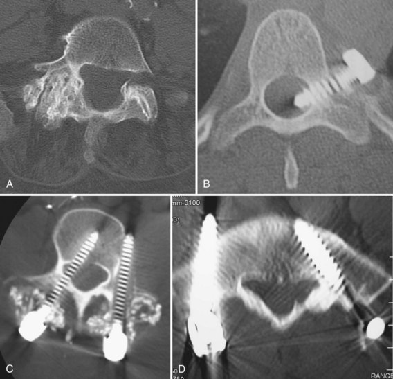
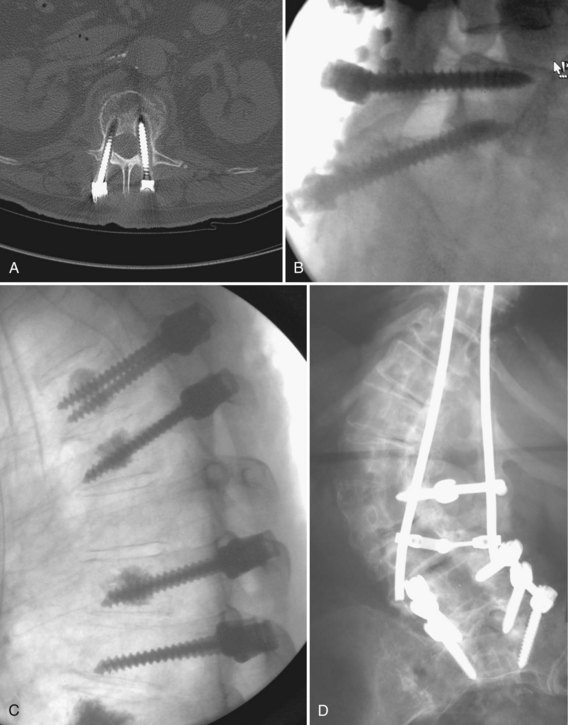
Clinical failure of transpedicular constructs occurs in one of two ways: through loosening with fixation failure or through failure to fuse. Loosening occurs as repetitive loading persists beyond the tolerance of bone. This is usually the result of delayed union or motion at a screw-bone interface, often from excessive activity. The screw is exposed to a combination of cantilever bending and axial pullout loads (Fig. 71–5). Subacute or acute bending failure and implant breakage results from cantilever bending loads in excess of the yield point of the screws resulting in acute failure and breakage. Even severely degenerated and collapsed discs undergo cyclic axial displacement during axial loading. These cyclic displacements may lead to significant cantilever loads and bending moments. These are most pronounced around the screw hub, inside the pedicle.
This effect is multiplied when the screw is forced to bear most or all of the anterior column axial loads, as with burst fractures. If a deformity reduction maneuver is performed during surgery, this subjects the screws to increased load. Typically, the end vertebrae are affected. Various techniques for correction, such as derotation maneuvers, have been described. A strategy that emphasizes correction in the middle segments of the construct with decreased corrective force at the terminal levels is associated with good reduction, while limiting axial tensile forces at the cranial end screw.79 After bony healing, fatigue failure of the implants may still theoretically occur but should no longer be of clinical concern. In less unstable situations, such as a minimal degenerative spondylolisthesis, unilateral transpedicular fixation was found to be as good as bilateral fixation.81
Faraj and Webb82 reviewed complications related to transpedicular instrumentation in 648 consecutively inserted screws. Instrumentation was performed for various diagnoses, including scoliosis (34 patients), degenerative lower lumbar spinal disease (25 patients), and lumbosacral spondylolisthesis (3 patients). Intraoperative complications included three cases of screw misplacement, one case of nerve root impingement, two cases of cerebrospinal fluid leak, and two pedicle fractures. Postoperatively, deep wound infections were encountered in four patients, and two loose screws and one rod-screw disconnection occurred. The authors concluded that pedicle screw fixation has an acceptable complication rate and that neurologic injury during this procedure is unlikely.
Another series sought to quantify retrospectively pedicle screw–related complications in 105 consecutive operations. Overall, complications of varying severity were noted in 54%. The rate of deep infections was 4.7%, and all were successfully cured by débridement and antibiotics. Although 6.5% of cases had screw misplacement, there were no permanent neurologic complications. Screw breakage occurred in 12.4% of the patients, inevitably leading to loss of correction. Breakage was especially likely in cases of L5-S1 spondylolisthesis where reduction was performed without anterior support.83
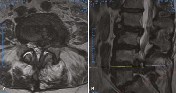
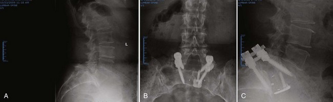
Spondylolisthesis may be stabilized with or without an attempt at slip reduction. Reduction maneuvers include rod contouring with an additional cranial fixation point with screws with an extended head into which the rod can be forcibly delivered, translating the slipped segment posteriorly.84,85 Some screw-rod systems have been designed solely for slip reduction.86 With reduction of an L5-S1 spondylolisthesis, there is increased risk of a postoperative L5 root palsy.87 Pedicle screw constructs are also routinely used to increase the likelihood of fusion in the surgical management of junctional stenosis, degenerative spondylolisthesis or scoliosis, prior pseudarthrosis, and more than a three-level fusion (Fig. 71–6).
Typically, pedicle screw fixation is avoided in the presence of overt infection, but it may be considered in cases of significant instability. Relative contraindications to pedicle screw fixation include very small pedicles, marked osteoporosis, and inadequate anterior column support. In corpectomy models, 100% cyclic fatigue failure has been reported if anterior reconstruction and grafting has not been performed.88,89 With partial anterior column load bearing, the posterior screw construct attempts much of the load bearing through cantilever forces.
Ultimately, the surgeon is left with the decision of when to perform pedicle screw fixation. Conflicting clinical outcomes have been reported, with good clinical outcome not correlating well with solid fusion. Although instrumentation enhances the rate of spinal fusion in degenerative conditions of the lumbar spine, such fusion does not guarantee a clinically successful outcome. Conversely, excellent results can be obtained in the setting of radiographic pseudarthrosis.90 One prospective randomized controlled trial of 130 patients evaluated supplementary pedicle screw fixation in posterolateral lumbar spinal fusion and found that fusion rates were not significantly different between instrumented and uninstrumented groups. Although functional outcome, as assessed by the Dallas Pain Questionnaire, improved significantly in uninstrumented and instrumented groups, there were no significant differences in outcome between the two groups. A trend toward higher patient satisfaction was noted in the instrumented group (82%) versus the uninstrumented group (74%). The addition of pedicle screws significantly increased operative time, blood loss, and early reoperation rate. The two infections in that series occurred in the implant group, and significant symptoms from screw misplacement were seen in 4.8% of the instrumented patients. The authors concluded that these results did not justify the general use of pedicle screw fixation as a routine adjunct to posterolateral lumbar fusion.91
A similar prospective randomized controlled trial with 5-year follow-up was performed in 129 patients with severe chronic low back pain from either degenerative instability or isthmic spondylolisthesis. In that series, the reoperation rate was significantly higher in the instrumented group (25%) than the uninstrumented group (14%). There was no difference in work capacity between the two groups and no significant difference between the instrumented and uninstrumented groups in regard to functional outcome, as measured by the Dallas Pain Questionnaire and Low Back Pain Rating Scale. When the subgroups of isthmic and degenerative spondylolisthesis were analyzed separately, patients with isthmic spondylolisthesis had a significantly better outcome after posterolateral fusion without supplemental instrumentation compared with instrumented fusion (P < .03). Patients with primary degenerative spondylolisthesis had more significant improvement with instrumented posterolateral fusion (P < .02).7
Another prospective randomized study investigated the role of transpedicular fixation with posterolateral fusion in patients with adult isthmic spondylolisthesis; 37 patients underwent fusion with pedicular fixation, and 40 had uninstrumented fusion. At 2-year follow-up, the level of pain and functional disability were similar in the two groups, and there was no significant difference in fusion rate.92 In a separate retrospective review, 57 patients underwent posterior decompression and fusion for L4-5 degenerative spondylolisthesis, with half having transpedicular screw instrumentation. The clinical results and fusion rate were similar in the two groups. The authors concluded that the routine addition of pedicular fixation in these patients was unnecessary.93
Percutaneous transpedicular constructs have been introduced more recently. These may be used to stabilize an ALIF or on the contralateral side of a minimally invasive transforaminal lumbar interbody fusion. Some systems employ a rod-insertion device that links to the screw extension sleeves and allows a precut contoured rod to be placed through the screw saddles via a small stab wound and a muscle-splitting technique. A remote engagement of the screw-locking mechanism is then employed. Long-term outcomes for these techniques are sparse, but short-term success has been reported in small numbers of patients. Proponents of this technique believe that paraspinous tissue trauma is minimized without compromising the quality of spinal fixation.94
Technical Aspects
In patients with complex deformity, correct rod bending may be quite difficult. The rod should not be contoured in more than one plane at a time. In children and patients with flexible deformities, the rod can be contoured to fit the screws and rotated into proper sagittal balance. Alternatively, a series of force vectors and direct rotational maneuvers may be undertaken. In patients with rigid curves and most adults, accurate rod contouring to fit into the screws can be difficult. It is often helpful to use instead lateral connectors between the rod and screw. Some surgeons, in an effort to maximize correction power, use separate rods in the upper and lower portions of a stiff, dual curve deformity and connect them with a domino on one side and use a neutralization rod on the opposite side.62
When bending rods for hook-based constructs, slight deviation from perfect contour puts a moment on the hook. In the thoracic spine, a kyphotic moment pulls the hook away from the cord. Generally, the aim is for a 30-degree thoracic kyphosis with its apex at T7 or T8. The lumbar lordosis should be 45 degrees with an apex at the L2-3 interspace. The rod should change from kyphosis to lordosis at the T12-L1 interspace. After placement of the hooks, the convex rod is placed first. The more mobile the hooks, the more easily the rod engages. Hook mobility is a function of the amount of bone resection during hook placement. The ease of rod insertion improves with spine mobility, which is a function of facet resection. Torsional stability of anterior and posterior dual rod constructs improves with the use of cross-links between the rods.95 Depending on the number of motion segments instrumented, the degree of instability of the spine, and the strength of the bone-implant interface, placement of one to three cross-links has been recommended.96,97 If two cross-links are used, one should be as proximal as possible and the other as distal as possible. If the instrumentation exceeds 30 cm in length, a third transverse connector should be considered in the middle. In some cases, there is little space for a cross-link between the bulky heads of polyaxial screws. In such instances, the rods could be extended caudally or cranially and a cross-link placed along the extension. Care should be taken to avoid injury to the proximal facet joint by the connector. The addition of a cross-link may mechanically compensate for a missing pedicle screw in a polysegmental construct.96
One cadaveric study of transpedicular fixation across the thoracolumbar junction found that rotational and bending stiffness increased significantly with the number of cross-links placed.98 Another study compared constructs using no, one, or two cross-links.95 This study found that two cross-links were no more effective than one in significantly increasing axial, flexion, and lateral stiffness, although additional cross-links significantly improved the torsional stiffness of the construct. When comparing different types of cross-links, larger cross-sectional area was associated with greater increases in stiffness.
Interbody and Anterior Lumbar Interbody Fusion Techniques
Modern forms of anterior thoracolumbar instrumentation were initially developed separately by Zielke and Dwyer in the late 1960s to mid-1970s.53 Their techniques of anterior release and fixation allowed better deformity correction, necessitating fewer fused segments. These deformity techniques were adapted to traumatic conditions by Kaneda and Dunn. Use of these devices began to wane, however, because of reports of catastrophic vascular erosions.
Use of anterior plate and rod constructs has become more common. As with posterior fixation constructs, anterior systems are used to provide stability, to attain or maintain alignment, or to improve or accelerate fusion. Anterior procedures are often indicated to release and stabilize thoracolumbar deformity correction (scoliosis, spondylolisthesis, kyphosis). Beyond deformity procedures, these goals are sought in the stabilization of fractures or unstable tumors. Anterior instrumentation is commonly used to provide stability when anterior corpectomy is used for the treatment of burst fractures.99 In addition, restoration of sagittal alignment and the vertebral weight-bearing column is best accomplished anteriorly.100 More controversial indications for anterior surgery include its role in treating discogenic pain. Relative contraindications for anterior procedures include severe osteoporosis. The less expansile nature of anterior approaches decreases their utility in patients with multisegmental pathologic processes (e.g., multiple spine metastases) where multilevel exposure is required. Contraindications to abdominal or thoracic surgery also limit the utility of these procedures in some patients. Patients with multiple prior abdominal or retroperitoneal surgeries and patients with severe pulmonary dysfunction might be better treated with a posterior reconstruction.
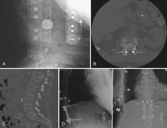
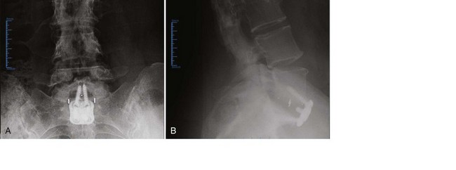
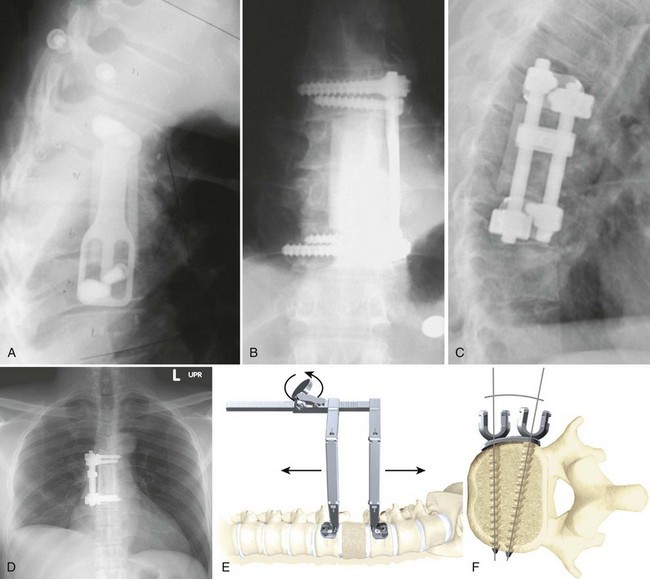
Biomechanical animal studies have shown the efficacy of obtaining a solid fusion with anterior fusion and instrumentation.101,102 Purported benefits of anterior fixation include decreased rates of pseudarthrosis (particularly in smokers), graft extrusion, postoperative kyphosis, and graft subsidence.103 Anterior plating reduces the need for postoperative bracing and allows early rehabilitation (Fig. 71–7).104,105
Mechanically, anterior devices function in a neutralization mode. The implant partly shields axial stress and minimizes torsional bending and shearing. They also provide resistance to vertebral extension.106 Typically, titanium alloys provide a more optimal stiffness modulus and permit better postoperative imaging capability than stainless steel.107
Anterior systems rely on softer cancellous vertebral body bone with thin cortices, as opposed to posterior pedicle screw systems that rely on cortical pedicle bone. Gurwitz and colleagues108 assessed the stability of several constructs in a burst fracture model. Axial stiffness and torsional rigidity were measured before and after posterior instrumentation alone, posterior instrumentation with anterior strut grafting, and anterior instrumentation with anterior strut grafting. They found that posterior instrumentation alone was associated with 76% less axial stiffness. The addition of an anterior strut rendered the construct as stiff as the intact spine. Anterior struts with anterior instrumentation were as strong as the intact spine in axial loading. All of these constructs were 30% less rigid in torsion compared with the intact spine.
Although most anterior column spacers are used to improve the alignment and rate of spinal fusion, some are used without attempted fusion. Traditionally, PMMA was one of the first and simplest constructs for reconstruction of corpectomy defects. It is currently rarely used, but it may be considered in patients with limited life expectancy and is best limited to one-level or two-level corpectomies only. The stability of this construct is improved by the use of Steinmann pins that can be placed through the PMMA construct and embedded into the vertebral endplates above and below the defect. C-clamps and other devices have been used to improve endplate support.109 In an open total spondylectomy model, PMMA can be packed into the anterior defect from a posterior approach. As with all interbody procedures, endplate coverage is important in avoiding subsequent subsidence.110 A mechanical assessment of this construct in cadaveric spines found that only combined approaches with posterior screws and anterior PMMA restored the spine to its previous state. With the posterior elements removed, use of PMMA and anterior instrumentation or anterior pins was unable to restore the motion segment stability.111
Although morcellized graft material has been used alone, a structural graft or morcellized graft material within an interbody cage is more typically selected. Options for interbody grafts include various types of structural autogenous grafting (e.g., rib or tricortical iliac crest) or allograft struts (e.g., rings or dowels). No mechanical advantage of supplemental screw placement into the graft or cage has been shown.106
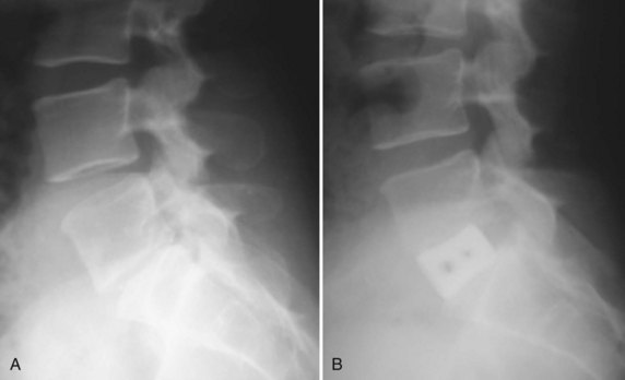
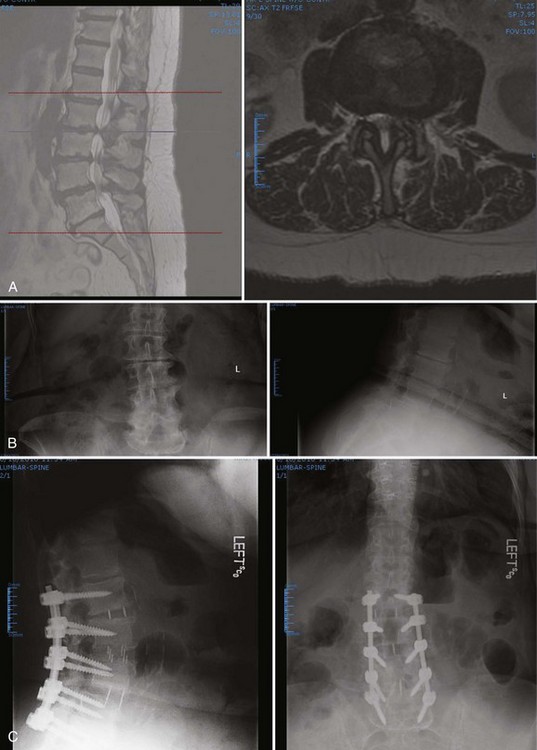
Regardless of which strut graft, spacer, or cage is placed, a few rules governing endplate and fusion bed preparation must be followed. First, as much disc material as possible should be removed because residual disc material actively discourages fusion. This is more easily and completely attained by a direct anterior approach than a posterior approach via a posterior lumbar interbody fusion or transforaminal lumbar interbody fusion. Second, the endplate cartilage should be removed down to bleeding bone, but the subchondral bone endplate should be preserved. Some surgeons advocate endplate perforation to facilitate bone ingrowth from the vertebral body into the graft. Because loads and, consequently, the risk of implant subsidence are much higher in the thoracolumbar spine than in the cervical spine, the endplate must be carefully protected, particularly in osteoporotic and obese patients (Fig. 71–8).
Anterior implants can be classified as either unconstrained or constrained. The earliest attempts at anterior fixation used dynamic compression plates, originally designed for the appendicular skeleton, across disc spaces. At the present time, most unconstrained implants consist of a single rod system used in the anterior management of scoliosis.112
The advantage of an unconstrained system is its ease of insertion. The disadvantage is its poor rotational stability.113 Most unconstrained systems provide no fixed angle between the bone anchor (typically a screw) and the longitudinal member, which increases the risk of screw backout, especially if placed unicortically. Unconstrained anterior systems are often used in deformity surgery and are augmented with bracing. In more unstable settings involving trauma or tumor, their role is best limited to the mid-thoracic spine with an intact rib cage and sternum.112 The greater stresses associated with the thoracolumbar or lumbar spine limit the usefulness of unconstrained systems there to cases in which supplemental posterior instrumentation would be used.
Constrained systems include rigid fixation between the anchor point and the longitudinal member, be it a plate or a rod. Constrained systems can be divided into plate systems and dual rod systems. Plating systems are generally considered easier to place and lower profile than dual rod systems. Anterior plates are not quite as rigid as dual plating systems, particularly with regard to torsional stability.114
Current examples of rigid locking plates include the Z-plate (Medtronic, Minneapolis, MN) and the University Plate (DePuy Spine, Raynham, MA). The other major category of constrained anterior fixation devices is dual rod systems. A classic example of this implant type is the Kaneda Device (DePuy Spine, Raynham, MA). The advantages of constrained systems include the ability to apply compression across the graft.115 The fixed angle between the screw and the plate or rod allows maintenance of sagittal balance. A fixed angle can also be a disadvantage because it limits screw placement options, such as in hemicorpectomy, in which screws may need to be placed close together. Other potential disadvantages include implant bulk. Lateral, rather than anterolateral, placement is key in avoiding the great vessels and risk of vascular erosion.
Application of dual rod systems involves placing screws through spiked plates into the lateral vertebral body.115 The plates decrease axial load through the screws by distributing axial load across the vertebral body. Distribution of this load is helpful because of the thinness of the lateral vertebral cortices. Without the plates, the screws could tear through the lateral vertebral body wall. In some systems, individual screw plates are available. These single screw plates spread vertical loads over a smaller area but have increased placement options.
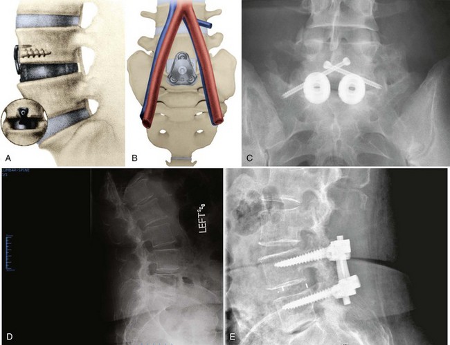
More recently, plates designed to stabilize the lower lumbar spine after anterior lumbar interbody fusions have been offered by various manufactures. An example is the Pyramid Plate (Medtronic, Memphis, TN). This plate is shaped to fit in the bifurcation of the great vessels anterior to the L5-S1 interspace and to provide extension stability to the spine. At this point, there is little in the way of either biomechanical or clinical data.116 The goal of these plates is to limit the need for routine supplementary posterior fixation after ALIF. Some anterior thoracolumbar implants are placed more to contain graft material than to control segmental motion. Numerous resorbable implants have been developed for this purpose.117 More common are screw-washer constructs or various small plates that attach to one vertebral body and span the intervertebral disc space.118 At the present time, there are few biomechanical data to support their use.
Specifics of Anterior Lumbar Interbody Fusion
In the past 20 years, spine surgeons have become increasingly comfortable with anterior, retroperitoneal approaches to the low lumbar spine. The least controversial indications for anterior cages include reconstruction of tumors or vertebral body fractures. Thoracolumbar cages or strut allografts (see Figs. 71-7 and 71-8) are often employed in the reconstruction of the following:
In addition to numerous interbody cages, an expanding number of allografts have become available (Fig. 71–9). These may be “off-the-shelf” sections of femur, tibia, humerus, or fibula, which the surgeon cuts into the desired size and shape or one of myriad machined “bone products.” Commercial bone implants are typically prefabricated to specific sizes and may have special surface textures to resist extrusion.
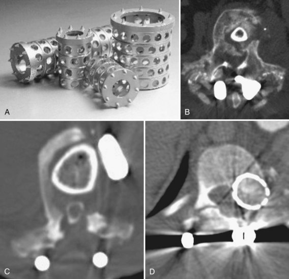
The rationale behind machined allograft and manufactured cages includes the following:119
Although allograft bone spacers may be used alone, they, similar to their metal counterparts, are typically filled with bone graft or bone morphogenetic protein. Interbody spacers come in various shapes and sizes. Cage materials include metal, bone, carbon fiber, PMMA, or PEEK. Numerous absorbable polymers, such as polylactic acid, are also undergoing testing.122 Each interbody device has different characteristics, such as modulus of elasticity.
One of the disadvantages of metal cage implantation lies in plain radiographic assessment of fusion. Assessment may be improved when carbon fiber, PEEK, or similar biomaterials are used.123 Even with radiolucent cages, differentiation of bone adherence versus through-growth (true fusion) is difficult, however.
Some differences in bone healing relate to the stiffness of the cage. Stiffer cages stress-shield the bone graft within. The modulus of elasticity with PEEK is closer to host bone and may load the graft more completely.124 With resorbable cages, the graft is gradually loaded to a greater and greater degree as the cage is enzymatically digested. One study found that this property was associated with improved fusion rates compared with titanium cages.122
For posterior interbody cage insertion, various contoured and banana-shaped cages have been designed to facilitate insertion and match the native endplate contour. Anterior cages are broadly divided by purpose into interbody and corpectomy devices. There are two main cage varieties: vertical and horizontal. Vertical devices typically fill corpectomy defects, whereas horizontal (cylindric) cages are used in discectomy procedures. For the latter, the mechanical goal is interspace distraction and restoration of annular tension.125,126
The metallic tines of vertical cages and the threads or texturing of horizontal cages allow them to resist torsion and displacement better than smooth bone grafts. Horizontal cage designs can be subdivided further by shape into screw-in, box, or mesh. Screw-in cages are exemplified by threaded cylinders such as the Bagby and Kuslich (BAK) device. Box cages are rectangular with flat and textured bearing surfaces to improve axial stiffness and resist extrusion. Numerous manufacturers market machined allograft with surface grooves for a similar effect. The relative merits of each of these designs continue to be debated.127
By providing disc space distraction, interbody devices and procedures restore foraminal height. Interbody techniques can also provide indirect reduction of central canal compression. One cadaveric CT study found that anteriorly or laterally placed interbody devices can reduce anterior listhesis and increase canal and foraminal volume in a degenerative spondylolisthesis model.128 One clinical study followed a series of 56 patients with back pain, neuroclaudication, or both from degenerative spondylolisthesis and spinal stenosis who underwent ALIF for reduction and fusion. Outcomes were comparable to the published outcomes of in situ fusion after formal laminectomy, avoiding the risk of epidural fibrosis and “fusion disease” associated with posterior decompression and fusion.129
All strut grafts, disc replacements, cages, and other anterior spacers are subject to subsidence and extrusion.130,131 The rate and degree of this subsidence is related to cage geometry and sizing, endplate coverage, and preparation.132,133 Several studies have shown excellent early interspace distraction but gradual cage with further follow-up. One clinical study of dual rectangular cages found that 76% of patients developed subsidence, more often into the superior than the inferior endplate, although it did not appear to affect fusion rates or clinical outcomes.134 The authors describe this subsidence as typically occurring by 4 months postoperatively. In that study, mean preoperative intervertebral disc height was 11.6 ± 3.1 mm, immediate postoperative height was 16.9 ± 2.0 mm, and final follow-up disc height was 13.2 ± 2.4 mm.
Cylindric implants have significantly more subsidence than plate and graft constructs, rectangular cages, or cages with lateral “wings” for increased axial stability.135 Lateral positioning on the endplate is associated with decreased rates of subsidence. Ultimately, cage size and placement in the disc space are more important than implant design.136 For similar reasons, subsidence is a major concern for disc replacement procedures. In contrast to fusion procedures, there is no point at which the construct can be said to be healed in position. Implant sizing is crucial. Because an overly large implant is virtually impossible to insert into a degenerated and collapsed disc space, an undersized implant is more commonly inserted owing to difficulty in adequately distracting the collapsed disc space. Because small implants cover very little of the vertebral endplate and offer virtually no end bearing, central positioning of the device risks endplate subsidence.137 Finally, if the patient subsequently develops osteoporosis, endplate support itself may decrease.
The lateral approach used in the thoracolumbar approach limits subsequent instrumentation placement options. A laterally placed plate is less able to prevent segmental spine extension than a plate on the anterior vertebral surface When approaching the lower lumbar spine anteriorly, the retroperitoneal approach is generally preferred (Fig. 71–10). Transperitoneal approaches enjoyed a short burst of popularity in the mid-1990s when endoscopic techniques were used for threaded cage placement. Although this attempt at less invasive fusion surgery has since given way to mini-open retroperitoneal approaches, it signaled a turning point in the way many surgeons viewed the relative morbidity of anterior and posterior surgical approaches.28
Minimal Access Surgery
Numerous mini-open modifications of the standard retroperitoneal exposure have been described. These modifications rely chiefly on the experience of the access surgeon and powerful retractor systems to minimize the incision length. In one retrospective 2-year follow-up, 28 patients underwent ALIF via a 6-cm to 10-cm left lower quadrant transverse skin incision.29 A paramedian anterior rectus fascial Z-plasty allowed access to the retroperitoneal space for placement of various implants. No vascular, visceral, or urinary tract injuries occurred, but a mild ileus was noted in three cases. Another report described similar use of a 5-cm left flank incision in 25 patients. No injury to the great vessels or neurologic deterioration was noted.30 This approach is safe, uses a small skin incision, avoids cutting the abdominal wall musculature, allows various interbody fusion techniques, and does not require peritoneal violation or endoscopic instrumentation. Other advantages include fewer x-rays with reduced radiation exposure during surgery and a shortened learning curve because the approach is similar to the anterior open lumbar technique.
Kaiser and colleagues31 performed a retrospective comparison of mini-open and endoscopic ALIF in approximately 100 patients. They found that operative times were longer and the risk of retrograde ejaculation was higher with the laparoscopic approach than with the mini-open approach. Length of stay was increased, however, and the immediate postoperative complication rate was greater after mini-open ALIF procedures.
An endoscopically assisted retroperitoneal approach has been termed the balloon-assisted endoscopic retroperitoneal gasless (BERG) approach. In one study of 46 individuals, various devices, including cylindric cages, femoral ring allografts, and vertical cages, were placed. Complications included a left common iliac vein injury not requiring operative repair and a far-lateral cage placement. The average hospital stay was 3 days. An advantage of the BERG approach over traditional endoscopic access is its ability to use standard orthopaedic instruments and implants.32
Minimally disruptive approaches to the anterior lumbar spine continue to evolve in a quest to reduce approach-related morbidity. One innovation is a lateral retroperitoneal, transpsoas approach to the anterior disc space that allows sufficient access for a complete discectomy, distraction, and interbody fusion without the need for an approach surgeon. Two companies have an FDA-approved device: The XLIF is from Nuvasive (San Diego, CA), and DLIF is from Medtronic (Minneapolis, MN). Advocates of minimal access spinal approaches cite certain advantages over open procedures, including decreased postoperative pain and narcotic requirements, shorter hospital stay, less blood loss, and smaller incisions. The minimally invasive anterolateral approach allows access to the lumbar spine through the retroperitoneal space (Fig. 71–11).
Motion-Preserving Implants
Dynamic Rod Systems
Numerous coils, springs, jointed rods, and semielastic cords have been devised to connect to pedicle screws. Some of these devices are intended to be used as less rigid fusion devices. Others are meant to “top off” the most cranial level of a long fusion construct theoretically to decrease the risk of adjacent-segment degeneration because less rigid fixation is believed to be associated with reduced adjacent-segment motion compared with rigid fixation.138
The Leeds-Keio ligamentoplasty was designed in the 1980s as an alternative stabilization method for patients with spondylolisthesis. Since 1990, this fabric ligament, originally developed for anterior cruciate ligament reconstruction, has been tied across adjacent vertebrae through drill holes in the pars with acceptable clinical results.139 Mechanical testing reveals adequate strength and fatigue characteristics, but the device has not been subjected to much investigation in North America.140 One system, in preclinical testing, uses flexible rods for percutaneous insertion but fills these rods with a self-curing polymer to increase subsequent rigidity.141 Most dynamic rod devices are intended to treat mechanical back pain associated with some forms of lumbar degenerative disease. Although these systems typically rely on pedicle screws for fixation to the vertebral bone, the various systems have architecturally and materially quite different materials between these screws. Ideally, each design was logically constructed to “fix” a clearly delineated problem in the painful or degenerated spine. Each system apparently relies on a different theory of pain generation and uses different mechanical means to address the pain. In some cases, a clear hypothesis as to the source of the pain is not evident.
Dynamic posterior instrumentation began with the Graf ligament, which was an inelastic cord wrapped around two pedicle screws. The goal was to lock the motion segment into full lordosis, restricting flexion and preventing rotation.142 There was no experimental basis for this design concept, but clinical results were acceptable. Limitations of the Graf ligament included the increase in posterior anulus load it engendered. This increase led to late failure with back pain or earlier failure resulting from the marked lateral recess and foraminal stenosis the system caused.143
The most visible dynamic posterior stabilization system is the Dynesys (Zimmer, Warsaw, IN). As with the Graf system, the Dynesys system connects pedicle screws with a nonelastic ligament. In this case, a plastic cylinder surrounds the ligament and prevents hyperlordosis. At surgery, the ligament is threaded through the cylinder and pulled with a set 300-N force. This force approximates the two screw heads with the interposed cylinder. Active extension opens the anulus anteriorly without compressing it posteriorly. The Dynesys system limits full flexion and extension. The developers of the system claim it decreases pain by eliminating “parasitic” or “abnormal” movement. In addition to restricting the range of movement, it may also unload the disc, however, if the patient achieves a position of lordosis, so that the plastic cylinder becomes weight bearing.144,145 Limitations of the Dynesys system include the unpredictable degree to which it unloads the disc and the need for strong extensor musculature to maintain lordosis. Lordosis and load sharing by the plastic cylinder vary markedly with implant placement.146
The mechanical properties of the Dynesys system change over time. Initially, it is quite stiff, and it has received FDA clearance as a pedicle screw–based fusion construct.146 A major, multicenter, randomized trial of the Dynesys system in North America is in its data collection phase at the time of this writing. Numerous outcomes studies have been presented at spine meetings, but few have been published. The first of these was a prospective, multicenter study employing the Dynesys system in various “lumbar instability conditions.” There was no comparison (control) group. The authors assessed preoperative and 38-month postoperative pain, function, and radiologic data in a consecutive series of 83 patients. Cases included some patients with neural compression and some with axial pain syndromes. Fifty-six patients had concomitant decompression. Previous lumbar surgery had been performed in 30 patients. In eight cases, screw loosening was noted radiographically; in one, revision surgery was undertaken during the study period. Persistent pain led to implant removal and conversion to fusion in three cases. In seven cases, adjacent segment degeneration necessitated further surgery.
The authors reported that pain and function scores improved significantly, with visual analog scale (VAS) score for back pain improving from 7.4 to 3.1. Leg pain improved from 6.9 to 2.4. The Oswestry Disability Index (ODI) score declined from 55.4% to 22.9%. The authors concluded that Dynesys fixation compared well with conventional procedures and was a safe and effective alternative in the treatment of unstable lumbar conditions.144 The theoretical advantage of less adjacent-level degeneration is not substantiated, however.
Another report from a “disinterested research group” studied 50 consecutive patients receiving the Dynesys system; 31 patients, treated for various degenerative lumbar conditions, with at least 2-year follow-up mailed in a questionnaire. In this series, nearly 20% had required or were scheduled for further surgery. At follow-up, mean VAS back and leg pain scores were 4.7 and 3.8. In terms of back symptoms, 67% of patients reported that they had improved, 30% reported symptoms were the same, and 3% reported symptoms were worse after the surgery. Of patients, 64% noted improvement in their leg symptoms, 21% reported symptoms were the same, and 14% reported symptoms were worse. On a functional level, 40% had improved, 33% were the same, and 27% were worse. The authors concluded that because back and leg pain were significant at 2 years, only half of the patients had improvement in quality of life. Because the reoperation rate was high, there was “no support for the notion” that semirigid fixation results in better outcomes than fusion.145 These results are not encouraging. In particular, given that motion preservation is meant to protect the adjacent segment, the high rates of adjacent segment surgery are troubling.
Many newer systems are undergoing evaluation at the present time. Some have been implanted in humans abroad, but clinical data are sparse. The fulcrum-assisted soft stabilization (FASS) system was developed to address what was perceived as disadvantages of the Graf system. In the FASS system, a fulcrum is placed between the pedicle screws, in front of the ligament. The fulcrum distracts the posterior anulus. When the elastic ligament is placed posterior to the fulcrum, to compress the pedicle screw heads, the fulcrum transforms this posterior compression force to an anterior distraction force, which distracts the anterior anulus. The ligament creates the force that produces a lordosis, and it is not dependent on active muscle action, in contrast to in the Dynesys system.146
Interspinous Spacers
In June 2005, a randomized, controlled, prospective multicenter trial of 191 patients with neurogenic claudication compared outcomes of patients treated with X-STOP with outcomes of patients receiving nonoperative care.147 At 2 years, the symptom severity score of patients treated with X-STOP improved by 45.4% over mean baseline. The control group had only 7.4% improvement. Physical function improved 44.3% in the X-STOP group but declined in the controls. The authors concluded that the X-STOP provided effective treatment for patients with spinal stenosis (Fig. 71–12).
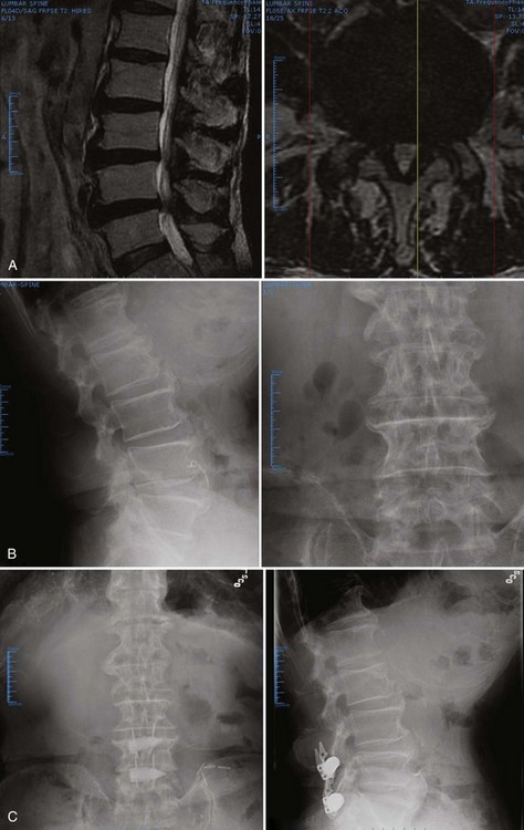
At least four other interspinous spacer devices are receiving increasing attention at new technology meetings. Most of these devices are intended to treat mechanical low back pain through either distraction or restriction of motion. One example is the Wallis (Zimmer, Warsaw, IN) implant, in which a semielastic blocker seeks to dampen forces passing through the posterior elements while decreasing the neutral zone.148 The first-generation implant, with a titanium blocker and an “artificial ligament” made of Dacron, was developed in 1986. More than 300 patients were implanted during 1988-1993. Subsequently, the Wallis implant, made of PEEK, was developed. Without permanent fixation into the vertebral bone, the “floating” design of the Wallis and similar implants seeks to avoid the risk of loosening encountered with pedicle screw–based and facet replacement–based dynamic stabilization systems. According to a more recent review of the Wallis implant, significant improvements in back pain were seen “without serious complications.”148 The Wallis system was recommended for (1) discectomy when massive fragment leads to substantial loss of disc material, (2) first disc herniation recurrence, (3) discectomy for herniation of a transitional disc with sacralization of L5, (4) degenerative disc disease at a level adjacent to a previous fusion, and (5) isolated endplate lesions leading to chronic low back pain.
Nucleus Replacement
The historical precursor to total disc replacement and nuclear replacement was the stainless steel Fernström ball. This spherical endoprosthesis was developed and implanted in the 1950s and 1960s as a spacer that allowed motion of the adjacent vertebrae.149 The shape of the device concentrated the loads on a small portion of the implant and vertebral endplate surface. Normal load distribution could not be recovered; because of concerns about device migration and subsidence, the device was subsequently abandoned.150
More recent efforts at nuclear replacement have sought less stiff materials, typically with viscoelastic behavior. These devices can be divided roughly into preformed implants and injected polymers that cure in situ. Minimally invasive delivery of injectable materials can be accomplished with small annular windows, decreasing the risk of implant extrusion. Preformed implants may have the advantage of improved mechanical strength and fatigue life, but several designs have been associated with high extrusion rates.151,152
An intermediate approach relies on open implantation of a containment scaffold with subsequent injection or inflation with a hydrogel or other incompressible liquid. An ideal nuclear replacement restores disc mechanics with much less normal tissue ablation than total disc arthroplasty. Some of these devices may offer shock absorption not seen with current total disc arthroplasty designs.153
Nuclear replacement devices may be indicated for primary treatment of early, painful lumbar disc degeneration. Alternatively, they may be placed at the time of discectomy in a patient with radicular complaints. In the latter case, the nuclear replacement seeks to maintain or restore disc height and function. In the short-term, this restoration of disc mechanics is thought to decrease postoperative back pain. Ideally, nuclear replacement would prevent further motion segment degeneration, decreasing the likelihood of more invasive and destructive surgeries such as fusion or disc arthroplasty.153,154
Contraindications for a nucleus prosthesis include disc height less than 5 mm, annular incompetence (in the form of major tears), grade II or greater spondylolisthesis, and Schmorl nodes. Many of the proposed devices remain in preclinical testing for biocompatibility and fatigue life as of this writing.155,156 The Raymedica PDN (Prosthetic Disc Nucleus, Minneapolis, MN) has undergone several small clinical trials with associated implant redesigns. The device consists of a hydrogel core encased in a polyethylene jacket. The hydrogel absorbs water and expands to fill the nuclear cavity. The jacket prevents the hydrogel from overexpansion. Initially, two devices were implanted at each operated level. After extrusion problems were encountered, a larger, single PDN was designed. Although the device was initially inserted solely through a large posterolateral annulotomy, the consequences of device extrusion into the canal have led to anterolateral insertions as well.157
Numerous short-term nuclear replacement outcomes studies have been presented, and a subset of these have been published. In one series, 300 patients mainly with radiculopathy were implanted, and a dramatic improvement in ODI and VAS scores was reported for most. The extrusion rate has exceeded 6%, however, even in more recent reports. Occasionally, an intense endplate inflammatory reaction with sclerosis and increased pain occurs.158 Klara and Ray159 reviewed the PDN data and found that, since 1996, 10% of the 423 patients undergoing PDN placement have been explanted.
In one more recent article, the authors sought to evaluate the efficacy of PDN for chronic discogenic back pain caused by degenerative disc disease.160 Of 48 patients undergoing nucleus replacement surgery from January 2001 through May 2002, 46 were followed for 6 months. The mean ODI score was 58.9% preoperatively and improved to 18% at the 1-year follow-up. VAS pain scores improved from a preoperative mean of 8.5 to 3.1 after 1 year. The mean Prolo Scale score also improved from 5.2 preoperatively to 7.2 at 1 year. There were four cases of device migration requiring revision surgery. According to the MacNab criteria, results were excellent in 5 patients (10.9%), good in 31 (67.4%), fair in 3 (6.5%), and poor in 7 (15.1%). The authors concluded that nucleus replacement with the PDN device seemed to be effective in treating patients with chronic discogenic back pain caused by degenerative disc disease. The high failure rate is disturbing, however.
Another emerging nuclear replacement is the spiral Newcleus (Centerpulse, Sulzer SpineTech, Minneapolis, MN). This polycarbonate urethane is shaped in a memory coiling spiral that can be inserted through a small annular window.161 Inside the disc space, it recoils to fill the nucleotomy defect and restore disc height. Theoretically, this design allows for an easily customized amount of the material to be implanted with little risk of extrusion. Korge and colleagues162 reported implantation into five humans with radicular pain caused by disc herniation. Two years after the implantation, there were no complications, the facet joints were completely functional, and there was clinical improvement indicated by improvement in VAS and ODI scores.
Lumbar Disc Arthroplasty
After the Fernström ball, the evolution of total disc and nuclear replacement diverged. Lumbar disc replacement, similar to nuclear replacement, is one of an emerging group of motion-preserving technologies whose clinical goals include reduction of pain and avoidance of the morbidity associated with fusion. Lumbar fusion for painful lumbar degeneration has a long, but storied, history and remains controversial. Most importantly, outcomes after these procedures are not consistently satisfactory. Significant numbers of patients remain on narcotic pain medications and remain unable to return to previous levels of employment.163
In 1982, in what was then Communist East Germany, Büttner-Janz and Schellnack164 initiated development of their artificial disc at the Charité Hospital in Berlin. They based their design on the “low-friction” principle used in total knee and total hip arthroplasty. In particular, they placed a polyethylene sliding core between two highly polished metal endplates. This sliding core was to mimic the movement of nucleus within its annular containment.
After preliminary mechanical testing, the SB CHARITÉ I disc was first implanted in 1984. In 1985, owing to axial migrations, the artificial disc was modified to SB CHARITÉ II, in which the metal endplates were enlarged with bilateral “wings” to improve support of the implant on the bony endplates of the vertebral bodies. Fractures in Modic II endplates and insufficient instrumentation for implantation led the designer to enlist major orthopaedic device manufacturer Helmut Link to assist in the development of the third generation. The currently available SB CHARITÉ III has basically remained unchanged since Link took over production in 1987. Since 1987, approximately 4000 SB CHARITÉ artificial discs have been implanted (Fig. 71–13).165
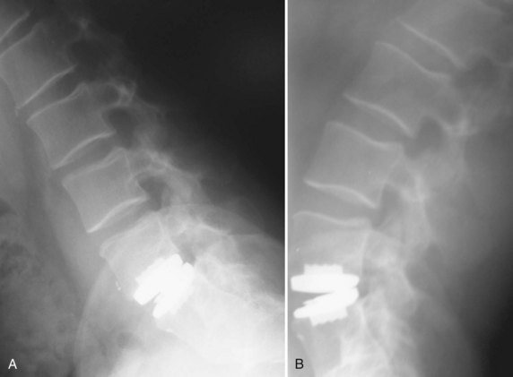
After the SB CHARITÉ, the next disc arthroplasty system was the Prodisc (Synthes Spine, Paoli, PA). The Prodisc is composed of two titanium endplates with a fixed polyethylene core between them. Motion occurs by articulation of only the upper plate on the convex superior surface of the constrained core. This device was designed and implanted into a group of patients after which the designer, Marnay, refrained from further implantations for 8 years. Subsequently, Marnay reported 8- to 10-year follow-up results on a group of 44 patients who received this prosthesis. He reported 78% good to excellent results.166
Current indications for lumbar disc replacement are as follows:
Contraindications are more controversial. Although subtle retrolisthesis related to disc collapse is acceptable, disc replacement with greater degrees of translational instability or spinal deformity should be avoided. Disc arthroplasty should not be performed in patients with marked facet osteoarthritis.167 The ideal arthroplasty patient presents with a single painful level with more than 4 mm of remaining disc height at that level. This ideal patient has intact posterior elements and no facet or adjacent-level degeneration.
Although disc arthroplasty seems promising, many important issues remain unresolved. First, design considerations include constrained versus semiconstrained implants and differing bearing surfaces, such as metal-on-metal versus metal-on-polyethylene.168 Proponents of metal-on-metal designs cite the increased rate at which polyethylene wears. Polyethylene particles could lead to osteolytic reactions and loss of bone stock. Thin polyethylene is subject to creep and cracking. Metal-on-metal, although more durable, is approached suspiciously by some spine surgeons because of concerns about metal ions leaching into the bloodstream. Currently available data are inadequate to compare these risks.
Initial wear rate studies seem to suggest excellent prospects for long-term viability.169,170 When particles are generated in significant numbers, however, they have been shown to migrate along the neuraxis to the brain.171 Serum metal ion levels in patients with long-standing hip prostheses were reported more recently. In this series of patients with implants in situ for more than 30 years, urine and serum cobalt, chromium, titanium, and vanadium were measured. In metal-on-polyethylene and metal-on-metal prosthetic groups, the levels of potentially carcinogenic ions were higher than in the control group. In patients with loose metal-on-metal articulations, the blood and urine cobalt levels were elevated to 50 and 300 times normal. Given that total disc arthroplasty is performed in a largely younger patient population, these metallic ion data should arouse concern and stimulate vigilance.172
The issue of device constraint remains unresolved as well. Proponents of unconstrained devices state that these are most capable of restoring the normal, coupled motion of the lower lumbar spine.173 Supporters of semiconstrained designs cite occasional polyethylene liner extrusions as evidence that more constraint is needed. The concept of “semiconstrained” is elusive: How much is enough; how much is too much? In particular, do these values hold over various levels of the lumbar spine? Current data suggest that the instantaneous axis of rotation is not constant, and changes depend on the joint position.174,175
If disc replacement systems restore motion, critics worry that improper motion may be worse than no motion. Disc degeneration rarely occurs in isolation. More typically, at least some facet degeneration coexists. One concern is that maintenance of motion would precipitate further facet degeneration. Given that the facets guide segmental motion, further facet degeneration may disrupt normal kinematics further.176 In a prospective, clinical study of 64 patients, low-grade facet arthrosis did not influence outcomes after implantation of a semiconstrained metal-on-metal total disc replacement. At 2-year follow-up, the preoperative ODI score of 43.8 had improved to 23.1. VAS back pain score had decreased from 7.6 to 3.2.
More constrained implants require more elaborate fixation methods to the host vertebral body.173 Several of the semiconstrained implants in the first generation of devices include keels. Although it is unclear if the keel offers a net advantage to the patient in terms of long-term stability, it would complicate any attempt to remove the implant. Two deep keels at adjacent levels of disc arthroplasty may subject the vertebral body to sagittal split fracture. For all but the tallest degenerated discs, current lumbar disc arthroplasty designs require marked disc space distraction. Too much distraction seems to decrease motion at the adjacent segment. Too little distraction risks implant extravasation.
Finally, critics of the current total disc arthroplasty systems have cited the limited outcomes literature relative to the thousands of discs that have been implanted worldwide. They also point out the suboptimal outcomes reported in the published articles.177 In particular, the actual amount of motion preserved may be very low in some cases. In a recent retrospective study, 38 patients undergoing one-level and two-level total disc replacement were divided into two groups by the amount of postoperative motion recorded on flexion-extension radiographs at 8.6-year follow-up. Although improvements in ODI and Stauffer-Coventry scores were termed “modest” overall, patients with greater than 5 degrees of motion reported outcomes superior to those with less motion.
Summary
Key Points
1 Kostuik JP, Errico TJ, Gleason TF. Techniques of internal fixation for degenerative conditions of the lumbar spine. Clin Orthop Relat Res. 1986;203:219-231.
2 Boachie-Adjei O, Squillante RG. Tuberculosis of the spine. Orthop Clin North Am. 1996;27:95-103.
3 Bono CM, Garfin SR. History and evolution of disc replacement. Spine J. 2004;4(6 Suppl):145S-150S.
4 Truumees E, Hilibrand A, Vaccaro A. Percutaneous vertebral augmentation. Spine J. 2004;4:218-229.
5 La Grone MO. Loss of lumbar lordosis: A complication of spinal fusion for scoliosis. Orthop Clin North Am. 1988;19:383-393.
6 France JC, Yasemski MJ, Lauerman WC, et al. A randomized prospective study of posterolateral lumbar fusion: Outcomes with and without pedicle screw instrumentation. Spine (Phila Pa 1976). 1999;24:553-560.
7 Bjarke Christensen F, Stender Hansen E, Laursen M, et al. Long-term functional outcome of pedicle screw instrumentation as a support for posterolateral spinal fusion: Randomized clinical study with a 5-year follow-up. Spine (Phila Pa 1976). 2002;27:1269-1277.
8 Katz JN, Lipson SJ, Lew RA, et al. Lumbar laminectomy alone or with instrumented or noninstrumented arthrodesis in degenerative lumbar spinal stenosis: Patient selection, costs, and surgical outcomes. Spine (Phila Pa 1976). 1997;22:1123-1131.
9 Mihara H, Onari K, Cheng BC, et al. The biomechanical effects of spondylolysis and its treatment. Spine (Phila Pa 1976). 2003;28:235-238.
10 Wall EJ, Bylski-Austrow DI, Kolata RJ, et al. Endoscopic mechanical spinal hemiepiphysiodesis modifies spine growth. Spine (Phila Pa 1976). 2005;30:1148-1153.
11 Hell AK, Campbell RM, Hefti F. The vertical expandable prosthetic titanium rib implant for the treatment of thoracic insufficiency syndrome associated with congenital and neuromuscular scoliosis in young children. J Pediatr Orthop B. 2005;14:287-293.
12 Cunningham ME, Frelinghuysen PH, Roh JS, et al. Fusionless scoliosis surgery. Curr Opin Pediatr. 2005;17:48-53.
13 Benzel E. Biomechanics of Spine Stabilization: Principles and Clinical Practice. New York: McGraw-Hill; 1995.
14 McAfee P, Cummingham B, Dmitriev A, et al. Cervical disc replacement-porous coated motion prosthesis: A comparative biomechanical analysis showing the key role of the posterior longitudinal ligament. Spine (Phila Pa 1976). 2003;28(Suppl):S176-S185.
15 Yoganandan N, Maiman DJ, Reinartz J, et al. Biomechanical effects of laminectomy on thoracic spine stability. Neurosurgery. 1993;32:604-610.
16 Heller JG, Shuster JK, Hutton WC. Pedicle and transverse process screws of the upper thoracic spine: Biomechanical comparison of loads to failure. Spine (Phila Pa 1976). 1999;24:654-658.
17 Elia M, Mazzara JT, Fielding JW. Onlay technique for occipitocervical fusion. Clin Orthop Relat Res. 1992;280:170-174.
18 Soyuncu Y, Yildrim FB, Sekban H, et al. Anatomic evaluation and relationship between the lumbar pedicle and adjacent neural structures: An anatomic study. J Spinal Disord Tech. 2005;18:243-246.
19 Sucato DJ, Duchene C. The position of the aorta relative to the spine: A comparison of patients with and without idiopathic scoliosis. J Bone Joint Surg Am. 2003;85:1461-1469.
20 Guanciale AF, Dinsay JM, Watkins RG. Lumbar lordosis in spinal fusion: A comparison of intraoperative results of patient positioning on two different operative table frame types. Spine (Phila Pa 1976). 1996;21:964-969.
21 Marsicano JG, Lenke LG, Bridwell KH, et al. The lordotic effect of the OSI frame on operative adolescent idiopathic scoliosis patients. Spine (Phila Pa 1976). 1998;23:1341-1348.
22 Kulkarni SS, Lowery GL, Ross RE, et al. Arterial complications following anterior lumbar interbody fusion: Report of eight cases. Eur Spine J. 2003;12:48-54.
23 Gokaslan ZL, Samudrala S, Deletis V, et al. Intraoperative monitoring of spinal cord function using motor evoked potentials via transcutaneous epidural electrode during anterior cervical spinal surgery. J Spinal Disord. 1997;10:299-303.
24 Schlenzka D, Laine T, Lund T. Computer-assisted spine surgery. Eur Spine J. 2000;9(Suppl 1):S57-S64.
25 Arand M, Hartwig E, Kinzl L, et al. Spinal navigation in cervical fractures—a preliminary clinical study on Judet-osteosynthesis of the axis. Comput Aided Surg. 2001;6:170-175.
26 Rampersaud YR, Pik JH, Salonen D, et al. Clinical accuracy of fluoroscopic computer-assisted pedicle screw fixation: A CT analysis. Spine (Phila Pa 1976). 2005;30:E183-E190.
27 Mirza SK, Wiggins GC, Kuntz C4th, et al. Accuracy of thoracic vertebral body screw placement using standard fluoroscopy, fluoroscopic image guidance, and computed tomographic image guidance: A cadaver study. Spine (Phila Pa 1976). 2003;28:402-413.
28 Kleeman TJ, Michael Ahn U, Clutterbuck WB, et al. Laparoscopic anterior lumbar interbody fusion at L4-L5: An anatomic evaluation and approach classification. Spine (Phila Pa 1976). 2002;27:1390-1395.
29 Dewald CJ, Millikan KW, Hammerberg KW, et al. An open, minimally invasive approach to the lumbar spine. Am Surg. 1999;65:61-68.
30 Huang TJ, Hsu RW, Chen SH, et al. Minimal access surgery in managing anterior lumbar disorders. Clin Orthop Relat Res. 2001;387:140-147.
31 Kaiser MG, Haid RWJr, Subach BR, et al. Comparison of the mini-open versus laparoscopic approach for anterior lumbar interbody fusion: A retrospective review. Neurosurgery. 2002;51:97-103.
32 Vazquez RM, Gireesan GT. Balloon-assisted endoscopic retroperitoneal gasless (BERG) technique for anterior lumbar interbody fusion (ALIF). Surg Endosc. 2002;17:268-272.
33 Molloy S, Saifuddin A, Allibone J, et al. Excision of an osteoid osteoma from the body of the axis through an anterior approach. Eur Spine J. 2002;11:599-601.
34 Lu K, Liang CL, Cho CL, et al. Oxidative stress and heat shock protein response in human paraspinal muscles during retraction. J Neurosurg. 2002;97(1 Suppl):S75-S81.
35 Ramsbacher J, Theallier-Janko A, Stoltenburg-Didinger G, et al. Ultrastructural changes in paravertebral muscles associated with degenerative spondylolisthesis. Spine (Phila Pa 1976). 2001;26:2180-2184.
36 Bridwell KH. Indications and techniques for anterior-only and combined anterior and posterior approaches for thoracic and lumbar spine deformities. Instr Course Lect. 2005;54:559-565.
37 Cybulski GR, Stone JL, Opesanmi O. Spinal cord decompression via a modified costotransversectomy approach combined with posterior instrumentation for management of metastatic neoplasms of the thoracic spine. Surg Neurol. 1991;35:280-285.
38 McLain RF. Spinal cord decompression: An endoscopically assisted approach for metastatic tumors. Spinal Cord. 2001;39:482-487.
39 Chacko AG, Moorthy RK, Chandy MJ. The transpedicular approach in the management of thoracic spine tuberculosis: A short-term follow up study. Spine (Phila Pa 1976). 2004;29:E363-E367.
40 Viale GL, Silvesrtro C, Francaviglia N, et al. Transpedicular decompression and stabilization of burst fractures of the lumbar spine. Surg Neurol. 1993;40:104-111.
41 McLain RF. Endoscopically assisted decompression for metastatic thoracic neoplasms. Spine (Phila Pa 1976). 1998;23:1130-1135.
42 Wiltse LL, Spencer CW. New uses and refinements of the paraspinal approach to the lumbar spine. Spine (Phila Pa 1976). 1988;13:696-706.
43 Khoo LT, Palmer S, Laich DT, et al. Minimally invasive percutaneous posterior lumbar interbody fusion. Neurosurgery. 2002;51(5 Suppl):S166-S171.
44 Doi K, Akino T, Shigetomi M, et al. Revascularized intercalary bone allografts with short-term immunosuppression with cyclosporine in the canine. Plast Reconstr Surg. 1998;101:793-801.
45 Kuklo TR, Bridwell KH, Lewis SJ, et al. Minimum 2-year analysis of sacropelvic fixation and L5-S1 fusion using S1 and iliac screws. Spine (Phila Pa 1976). 2001;26:1976-1983.
46 Molinari RW, Bridwell KH, Lenke LG, et al. Complications in the surgical treatment of pediatric high-grade, isthmic dysplastic spondylolisthesis: A comparison of three surgical approaches. Spine (Phila Pa 1976). 1999;24:1701-1711.
47 Early S, Mahar A, Oka R, et al. Biomechanical comparison of lumbosacral fixation using Luque-Galveston and Colorado II sacropelvic fixation: Advantage of using locked proximal fixation. Spine (Phila Pa 1976). 2005;30:1396-1401.
48 Mouhsine E, Wettstein M, Schizas C, et al. Modified triangular posterior osteosynthesis of unstable sacrum fracture. Eur Spine J. 2006;15:857-863.
49 Aebi M, Thalgott JS, Webb JK. AO ASIF Principles in Spine Surgery. Berlin: Springer; 1998.
50 White AA3rd, Panjabi M. Clinical Biomechanics of the Spine. Philadelphia: JB Lippincott; 1999.
51 Tsantrizos A, Baramki HG, Zeidman S, et al. Segmental stability and compressive strength of posterior lumbar interbody fusion implants. Spine (Phila Pa 1976). 2000;25:1899-1907.
52 Thompson RE, Barker TM, Pearcy MJ. Defining the neutral zone of sheep intervertebral joints during dynamic motions: An in vitro study. Clin Biomech. 2003;18:89-98.
53 Mohan AL, Das K. History of surgery for the correction of spinal deformity. Neurosurg Focus. 2003;14:e1.
54 Harrington PR. Treatment of scoliosis: Correction and internal fixation by spine instrumentation, June 1962. J Bone Joint Surg Am. 2002;84:316.
55 Shim CS, Lee SH, Jung B, et al. Fluoroscopically assisted percutaneous translaminar facet screw fixation following anterior lumbar interbody fusion: Technical report. Spine (Phila Pa 1976). 2005;30:838-843.
56 Margulies JY, Seimon LP. Clinical efficacy of lumbar and lumbosacral fusion using the Boucher facet screw fixation technique. Bull Hosp Joint Dis. 2000;59:33-39.
57 Luque ER. Interpeduncular segmental fixation. Clin Orthop Relat Res. 1986;203:54-57.
58 Zdeblick TA, Becker PS, McAfee PC, et al. Neuropathologic changes with experimental spinal instrumentation: Transpedicular versus sublaminar fixation. J Spinal Disord. 1991;4:221-228.
59 Jeng CL, Sponseller PD, Tolo VT. Outcome of Wisconsin instrumentation in idiopathic scoliosis: Minimum 5-year follow-up. Spine (Phila Pa 1976). 1993;18:1584-1590.
60 Drummond DS. A perspective on recent trends for scoliosis correction. Clin Orthop Relat Res. 1991;264:90-102.
61 Drummond DS. Harrington instrumentation with spinous process wiring for idiopathic scoliosis. Orthop Clin North Am. 1988;19:281-289.
62 Lee SM, Suk SI, Chung ER. Direct vertebral rotation: A new technique of three-dimensional deformity correction with segmental pedicle screw fixation in adolescent idiopathic scoliosis. Spine (Phila Pa 1976). 2004;29:343-349.
63 Polly DWJr, Potter BK, Kuklo T, et al. Volumetric spinal canal intrusion: A comparison between thoracic pedicle screws and thoracic hooks. Spine (Phila Pa 1976). 2004;29:63-69.
64 Liljenqvist U, Hackenberg L, Link T, et al. Pullout strength of pedicle screws versus pedicle and laminar hooks in the thoracic spine. Acta Orthop Belg. 2001;67:157-163.
65 Storer SK, Vitale MG, Hyman JE, et al. Correction of adolescent idiopathic scoliosis using thoracic pedicle screw fixation versus hook constructs. J Pediatr Orthop. 2005;25:415-419.
66 Hackenberg L, Link T, Liljenqvist U. Axial and tangential fixation strength of pedicle screws versus hooks in the thoracic spine in relation to bone mineral density. Spine (Phila Pa 1976). 2002;27:937-942.
67 Cheung KM, Luk KD, Leong JC. Radiographic assessment of pedicle hook placement. Spine (Phila Pa 1976). 1997;22:2106-2111.
68 Roach JW, Ashman RB, Allard RN. The strength of a posterior element claw at one versus two spinal levels. J Spinal Disord. 1990;3:259-261.
69 Hilibrand AS, Moore DC, Graziano GP. The role of pediculolaminar fixation in compromised pedicle bone. Spine (Phila Pa 1976). 1996;21:445-451.
70 Chang KW, Dewei Z, McAfee PC, et al. A comparative biomechanical study of spinal fixation using the combination spinal rod-plate and transpedicular screw fixation system. J Spinal Disord. 1988;1:257-266.
71 Orthopedic devices: Classification and reclassification of pedicle screw spinal systems; technical amendment. Final rule; technical amendment. Fed Reg. 2001;66:28051-28053.
72 Park P, Garton HJ, Jala JT, et al. Adjacent segment disease after lumbar or lumbosacral fusion: Review of the literature. Spine (Phila Pa 1976). 2004;29:1938-1944.
73 Christensen FB, Laursen M, Gelineck J, et al. Posterolateral spinal fusion at unintended levels due to bone-graft migration: No effect on clinical outcome in 19/130 patients. Acta Orthop Scand. 2001;72:354-358.
74 McAfee PC, Farey ID, Sutterlin CE, et al. The effect of spinal implant rigidity on vertebral bone density: A canine model. Spine (Phila Pa 1976). 1991;16(6 Suppl):S190-S197.
75 Etebar S, Cahill DW. Risk factors for adjacent-segment failure following lumbar fixation with rigid instrumentation for degenerative instability. J Neurosurg. 1999;90(2 Suppl):S163-S169.
76 Myers MA, Casciani T, Whitbeck MGJr, et al. Vertebral body osteopenia associated with posterolateral spine fusion in humans. Spine (Phila Pa 1976). 1996;21:2368-2371.
77 Lim TH, Goel VK, Weinstein JN, et al. A comparison of stress-induced porosity due to conventional and a modified spinal fixation device. J Spinal Disord. 1994;7:1-11.
78 Remes V, Helenius I, Schlenzka D, et al. Comparison of midterm clinical, functional, and radiologic outcomes Cotrel-Dubousset (CD) or Universal Spine System (USS) instrumentation in adolescent idiopathic scoliosis (AIS). Spine (Phila Pa 1976), 29. 2004:2024-2030.
79 Rohlmann A, Richter M, Zander T, et al. Effect of different surgical strategies on screw forces after correction of scoliosis with a VDS implant. Eur Spine J. 2006;15:457-464.
80 Shepard MF, Davies MR, Abayan A, et al. Effects of polyaxial pedicle screws on lumbar construct rigidity. J Spinal Disord Tech. 2002;15:233-236.
81 Commarmond J. [One-segment interbody lumbar arthrodesis using impacted cages: Posterior unilateral approach versus posterior bilateral approach]. Rev Chir Orthop Reparatrice Appar Mot. 2001;87:129-134.
82 Faraj AA, Webb JK. Early complications of spinal pedicle screw. Eur Spine J. 1997;6:324-326.
83 Jutte PC, Castelein RM. Complications of pedicle screws in lumbar and lumbosacral fusions in 105 consecutive primary operations. Eur Spine J. 2002;11:594-598.
84 Niu CC, Chen WJ, Chen LH, et al. Reduction-fixation spinal system in spondylolisthesis. Am J Orthop. 1996;25:418-424.
85 Aota Y, Kumano K, Hirabayashi S, et al. Reduction of lumbar spondylolisthesis using a CDI pedicle screw system. Arch Orthop Trauma Surg. 1995;114:188-193.
86 Hu SS, Bradford DS, Transfeldt EE, et al. Reduction of high- grade spondylolisthesis using Edwards instrumentation. Spine (Phila Pa 1976). 1996;21:367-371.
87 Ogilvie JW. Complications in spondylolisthesis surgery. Spine (Phila Pa 1976). 2005;30(6 Suppl):S97-S101.
88 Aligizakis AC, Katonis PG, Sapkas G, et al. Gertzbein and load sharing classifications for unstable thoracolumbar fractures. Clin Orthop Relat Res. 2003;411:77-85.
89 Sanderson PL, Fraser RD, Hall DJ, et al. Short segment fixation of thoracolumbar burst fractures without fusion. Eur Spine J. 1999;8:495-500.
90 Kim DH, Albert TJ. Update on use of instrumentation in lumbar spine disorders. Best Pract Res Clin Rheumatol. 2002;16:123-140.
91 Thomsen K, Christiansen FB, Eiskjaer SP, et al. 1997 Volvo Award winner in clinical studies. The effect of pedicle screw instrumentation on functional outcome and fusion rates in posterolateral lumbar spinal fusion: A prospective, randomized clinical study. Spine (Phila Pa 1976). 1997;22:2813-2822.
92 Ekman P, Moller H, Hedlund R. The long-term effect of posterolateral fusion in adult isthmic spondylolisthesis: A randomized controlled study. Spine J. 2005;5:36-44.
93 Kimura I, Shingu H, Murata M, et al. Lumbar posterolateral fusion alone or with transpedicular instrumentation in L4-L5 degenerative spondylolisthesis. J Spinal Disord. 2001;14:301-310.
94 Foley KT, Gupta SK. Percutaneous pedicle screw fixation of the lumbar spine: Preliminary clinical results. J Neurosurg. 2002;97(1 Suppl):S7-S12.
95 Dick JC, Zdeblick TA, Bartel BD, et al. Mechanical evaluation of cross-link designs in rigid pedicle screw systems. Spine (Phila Pa 1976). 1997;22:370-375.
96 Dick JC, Jones MP, Zdeblick TA, et al. A biomechanical comparison evaluating the use of intermediate screws and cross-linkage in lumbar pedicle fixation. J Spinal Disord. 1994;7:402-440.
97 Johnston CE2nd, Ashman RB, Baird AM, et al. Effect of spinal construct stiffness on early fusion mass incorporation: Experimental study. Spine (Phila Pa 1976). 1990;15:908-912.
98 Lynn G, Mukherjee DP, Kruse RN, et al. Mechanical stability of thoracolumbar pedicle screw fixation: The effect of crosslinks. Spine (Phila Pa 1976). 1997;22:1568-1572.
99 Harrington RM, Budorick T, Hoyt J, et al. Biomechanics of indirect reduction of bone retropulsed into the spinal canal in vertebral fracture. Spine (Phila Pa 1976). 1993;18:692-699.
100 Gurr KR, McAfee PC, Shih CM. Biomechanical analysis of anterior and posterior instrumentation systems after corpectomy: A calf-spine model. J Bone Joint Surg Am. 1988;70:1182-1191.
101 Zdeblick TA. A prospective, randomized study of lumbar fusion: Preliminary results. Spine (Phila Pa 1976). 1993;18:983-991.
102 Zdeblick TA. The treatment of degenerative lumbar disorders: A critical review of the literature. Spine (Phila Pa 1976). 1995;20(24 Suppl):126S-137S.
103 Bose B. Anterior cervical instrumentation enhances fusion rates in multilevel reconstruction in smokers. J Spinal Disord. 2001;14:3-9.
104 Vaccaro AR, Balderston RA. Anterior plate instrumentation for disorders of the subaxial cervical spine. Clin Orthop Relat Res. 1997;335:112-121.
105 Marchesi DG, Thalgott JS, Aebi M. Application and results of the AO internal fixation system in nontraumatic indications. Spine (Phila Pa 1976). 1991;16(3 Suppl):S162-S169.
106 Hitchon PW, Brenton MD, Serhan H, et al. In vitro biomechanical studies of an anterior thoracolumbar implant. J Spinal Disord Tech. 2002;15:350-354.
107 Kotani Y, Cunningham BW, Parker LM, et al. Static and fatigue biomechanical properties of anterior thoracolumbar instrumentation systems: A synthetic testing model. Spine (Phila Pa 1976). 1999;24:1406-1413.
108 Gurwitz GS, Dawson JM, McNamara MJ, et al. Biomechanical analysis of three surgical approaches for lumbar burst fractures using short-segment instrumentation. Spine (Phila Pa 1976). 1993;18:977-982.
109 Heller JG, Zdeblick TA, Kunz DA, et al. Spinal instrumentation for metastatic disease: In vitro biomechanical analysis. J Spinal Disord. 1993;6:17-22.
110 Wilke HJ, Kettler A, Claes L. [Stabilizing effect and sintering tendency of 3 different cages and bone cement for fusion of cervical vertebrae segments]. Orthopade. 2002;31:472-480.
111 Shannon FJ, DiResta BR, Ottaviano D, et al. Biomechanical analysis of anterior poly-methyl-methacrylate reconstruction following total spondylectomy for metastatic disease. Spine (Phila Pa 1976). 2004;29:2096-2102.
112 Wattenbarger JM, Richards BS, Herring JA. A comparison of single-rod instrumentation with double-rod instrumentation in adolescent idiopathic scoliosis. Spine (Phila Pa 1976). 2000;25:1680-1688.
113 Wattenbarger JM, Herring JA, Bronson D, et al. Mechanical testing of a single rod versus a double rod in a long-segment animal model. J Spinal Disord. 2001;14:232-236.
114 An HS, Lim TH, You JW, et al. Biomechanical evaluation of anterior thoracolumbar spinal instrumentation. Spine (Phila Pa 1976). 1995;20:1979-1983.
115 Kaneda K, Shono Y, Satoh S, et al. New anterior instrumentation for the management of thoracolumbar and lumbar scoliosis: Application of the Kaneda two-rod system. Spine (Phila Pa 1976). 1996;21:1250-1261.
116 Tsantrizos A, Andreou A, Aebi M, et al. Biomechanical stability of five stand-alone anterior lumbar interbody fusion constructs. Eur Spine J. 2000;9:14-22.
117 Vaccaro AR, Madigan L. Spinal applications of bioabsorbable implants. Orthopedics. 2002;25(10 Suppl):S1115-S1120.
118 Pavlov PW, Spruit M, Havinga M, et al. Anterior lumbar interbody fusion with threaded fusion cages and autologous bone grafts. Eur Spine J. 2000;9:224-229.
119 Wilke HJ, Kettler A, Goetz C, et al. Subsidence resulting from simulated postoperative neck movements: An in vitro investigation with a new cervical fusion cage. Spine (Phila Pa 1976). 2000;25:2762-2770.
120 Hacker RJ. A randomized prospective study of an anterior cervical interbody fusion device with a minimum of 2 years of follow-up results. J Neurosurg. 2000;93(2 Suppl):S222-S226.
121 Anderson DG, Albert TJ. Bone grafting, implants, and plating options for anterior cervical fusions. Orthop Clin North Am. 2002;33:317-328.
122 van Dijk M, Smit TH, Sugihara S, et al. The effect of cage stiffness on the rate of lumbar interbody fusion: An in vivo model using poly (L-lactic acid) and titanium cages. Spine (Phila Pa 1976). 2002;27:682-688.
123 Samandouras G, Shafafy M, Hamlyn PJ. A new anterior cervical instrumentation system combining an intradiscal cage with an integrated plate: An early technical report. Spine (Phila Pa 1976). 2001;26:1188-1192.
124 Ferguson S, Visser J, Polikeit A. The long-term mechanical integrity of non-reinforced PEEK-OPTIMA polymer for demanding spinal applications: Experimental and finite-element analysis. Eur Spine J. 2006;15:149-156.
125 Riew KD, Rhee JM. The use of titanium mesh cages in the cervical spine. Clin Orthop Relat Res. 2002;394:47-54.
126 Vaccaro AR, Cirello J. The use of allograft bone and cages in fractures of the cervical, thoracic, and lumbar spine. Clin Orthop Relat Res. 2002;394:19-26.
127 Kandziora F, Pflugmacher R, Schafer J, et al. Biomechanical comparison of cervical spine interbody fusion cages. Spine (Phila Pa 1976). 2001;26:1850-1857.
128 Vamvanij V, Ferrara LA, Hai Y, et al. Quantitative changes in spinal canal dimensions using interbody distraction for spondylolisthesis. Spine (Phila Pa 1976). 2001;26:E13-E18.
129 Bednar DA. Surgical management of lumbar degenerative spinal stenosis with spondylolisthesis via posterior reduction with minimal laminectomy. J Spinal Disord Tech. 2002;15:105-109.
130 Zdeblick TA, Phillips FM. Interbody cage devices. Spine (Phila Pa 1976). 2003;28(Suppl):S2-S7.
131 Gercek E, Arlet V, Delisle J, et al. Subsidence of stand-alone cervical cages in anterior interbody fusion: Warning. Eur Spine J. 2003;12:513-516.
132 Niu CC, Hai Y, Fredrickson BE, et al. Anterior cervical corpectomy and strut graft fusion using a different method. Spine J. 2002;2:179-187.
133 Truumees E, Demetropoulos CK, Yang KH, et al. Failure of human cervical endplates: A cadaveric experimental model. Spine (Phila Pa 1976). 2003;28:2204-2208.
134 Choi J, Sung K. Subsidence after anterior lumbar interbody fusion using paired stand-alone rectangular cages. Eur Spine J. 2006;15:16-22.
135 Eysel P, Fuderer S, Rompe JD, et al. [Initial instability of different cages for fusion of the cervical spine]. Zentralbl Neurochir. 2000;61:171-176.
136 Teo E, Yank K, Fuss FK, et al. Effects of cervical cages on load distribution of cancellous core: A finite element analysis. J Spinal Disord Tech. 2004;17:226-231.
137 Grant J, Oxland T, Dvorak T. Mapping the structural properties of the lumbosacral vertebral endplates. Spine (Phila Pa 1976). 2001;26:889-896.
138 Nohara H, Kanaya F. Biomechanical study of adjacent intervertebral motion after lumbar spinal fusion and flexible stabilization using polyethylene-terephthalate bands. J Spinal Disord Tech. 2004;17:215-219.
139 Mochida J, Suzuki K, Chiba M. How to stabilize a single level lesion of degenerative lumbar spondylolisthesis. Clin Orthop Relat Res. 1999;368:126-134.
140 Suzuki K, Mochida J, Chiba M, et al. Posterior stabilization of degenerative lumbar spondylolisthesis with a Leeds-Keio artificial ligament: A biomechanical analysis in a porcine vertebral model. Spine (Phila Pa 1976). 1999;24:26-31.
141 Teitelbaum GP, Shaolian S, McDougall CG, et al. New percutaneously inserted spinal fixation system. Spine (Phila Pa 1976). 2004;29:703-709.
142 Graf H. Lumbar instability: Surgical treatment without fusion. Rachis. 1992;412:123-137.
143 Grevitt MP, Gardner AD, Spilsbury J, et al. The Graf stabilisation system: Early results in 50 patients. Eur Spine J. 1995;4:169-175.
144 Stoll TM, Dubois G, Schwarzenbach O. The dynamic neutralization system for the spine: A multi-center study of a novel non-fusion system. Eur Spine J. 2002;11(Suppl 2):S170-S178.
145 Grob D, Benini A, Junge A, et al. Clinical experience with the Dynesys semirigid fixation system for the lumbar spine: Surgical and patient-oriented outcome in 50 cases after an average of 2 years. Spine (Phila Pa 1976). 2005;30:324-331.
146 Sengupta DK, Mulholland RC. Fulcrum assisted soft stabilization system: A new concept in the surgical treatment of degenerative low back pain. Spine (Phila Pa 1976). 2005;30:1019-1029.
147 Zucherman J, Hsu KY, Hartjen CA, et al. A multicenter, prospective, randomized trial evaluating the X STOP interspinous process decompression system for the treatment of neurogenic intermittent claudication: Two-year follow-up results. Spine (Phila Pa 1976). 2005;30:1351-1358.
148 Sénégas J. Mechanical supplementation by non-rigid fixation in degenerative intervertebral lumbar segments: The Wallis system. Eur Spine J. 2002;11(Suppl 2):S164-S169.
149 Fernstrom U. Arthroplasty with intercorporal endoprosthesis in herniated disc and in painful disc. Acta Chir Scand. 1966;355:154-159.
150 Klara PM, Ray CD. Artificial nucleus replacement: Clinical experience. Spine (Phila Pa 1976). 2002;27:1374-1377.
151 Bao QB, Yuan HA. Prosthetic disc replacement: The future? Clin Orthop Relat Res. 2002;394:139-145.
152 Bao Q, Yuan H. New technologies in spine: Nucleus replacement. Spine (Phila Pa 1976). 2002;27:1245-1247.
153 Dooris A, Goel VK, Grosland NM, et al. Load-sharing between anterior and posterior elements in a lumbar motion segment implanted with an artificial disc. Spine (Phila Pa 1976). 2001;26:E122-E129.
154 Wilke H, Kavanaugh S, Neller S, et al. Effect of a prosthetic disc nucleus on the mobility and disc height of the L4-5 intervertebral disc postnucleotomy. J Neurosurg (Spine 2). 2001;95:208-214.
155 Eysel P, Rompe J, Schoenmayr R, et al. Biomechanical behaviour of a prosthetic lumbar nucleus. Acta Neurochir (Wien). 1999;141:1083-1087.
156 Hedman T, Kostuik JP, Fernie GR, et al. Design of an intervertebral disc prosthesis. Spine (Phila Pa 1976). 1991;16(Suppl 6):S256-S260.
157 Bertagnoli R, Vazquez RJ. The Anterolateral TransPsoatic Approach (ALPA): A new technique for implanting prosthetic disc-nucleus devices. J Spinal Disord Tech. 2003;16:398-404.
158 Bertagnoli R, Schonmayr R. Surgical and clinical results with the PDN prosthetic disc nucleus device. Eur Spine J. 2002;11:S143-S148.
159 Klara P, Ray C. Artificial nucleus replacement. Spine (Phila Pa 1976). 2002;27:1374-1377.
160 Shim CS, Lee SH, Park CW, et al. Partial disc replacement with the PDN prosthetic disc nucleus device: Early clinical results. J Spinal Disord Tech. 2003;16:324-330.
161 Husson JL, Korge A, Polard JL, et al. A memory coiling spiral as nucleus pulposus prosthesis: Concept, specifications, bench testing, and first clinical results. J Spinal Disord Tech. 2003;16:405-411.
162 Korge A, Nydegger T, Polard JL, et al. A spiral implant as nucleus prosthesis in the lumbar spine. Eur Spine J. 2002;11:S149-S153.
163 Nachemson A, Zdeblick TA, O’Brien JP. Lumbar disc disease with discogenic pain: What surgical treatment is most effective? Spine (Phila Pa 1976). 1996;21:1835-1838.
164 Büttner-Janz K, Schellnack K. Bandscheibenendoprothetik, Entwick-lungsweg und gegenwärtiger Stand. Beitr Orthop Traumatol. 1990;3:137-147.
165 David T. Ten years or more follow-up with the LINK SB Charité artificial disc: 17 patients. J Arthroplasty. 2001;16(Suppl 1):S101-S105.
166 Zigler JE. Lumbar spine arthroplasty using the ProDisc II. Spine J. 2004;4(6 Suppl):260S-267S.
167 Bertagnoli R, Kumar S. Indications for full prosthetic disc arthroplasty: A correlation of clinical outcome against a variety of indications. Eur Spine J. 2002;11(Suppl 2):S131-S136.
168 Hallab N, Link HD, McAfee PC. Biomaterial optimization in total disc arthroplasty. Spine (Phila Pa 1976). 2003;28:S139-S152.
169 Anderson PA, Sasso RC, Rouleau JP, et al. The Bryan Cervical Disc: Wear properties and early clinical results. Spine J. 2004;4(6 Suppl):303S-309S.
170 Hallab NJ, Cunningham BW, Jacobs JJ. Spinal implant debris-induced osteolysis. Spine (Phila Pa 1976). 2003;28(Suppl):S125-S138.
171 Wang JC, Yu WD, Sandhu SH, et al. Metal debris from titanium spinal implants. Spine (Phila Pa 1976). 1999;24:899-903.
172 Dunstan E, Sanghrajka AP, Tilley S, et al. Metal ion levels after metal-on-metal proximal femoral replacements: A 30-year follow-up. J Bone Joint Surg Br. 2005;87:628-631.
173 Huang RC, Girardi FP, Cammisa FPJr, et al. The implications of constraint in lumbar total disc replacement. J Spinal Disord Tech. 2003;16:412-417.
174 Hindle RJ, Pearcy MJ. Rotational mobility of the human back in forward flexion. J Biomed Eng. 1989;11:219-223.
175 Pearcy MJ. Stereo radiography of lumbar spine motion. Acta Orthop Scand Suppl. 1985;212:1-45.
176 Gunzburg R, Mayer HM, Szpalski M, et al. Arthroplasty of the spine: The long quest for mobility. Eur Spine J. 2002;11(Suppl 2):S63-S64.
177 McAfee PC, Fedder IL, Saiedy S, et al. SB Charite disc replacement: Report of 60 prospective randomized cases in a US center. J Spinal Disord Tech. 2003;16:424-433.
[/level-membership-for-orthopaedics-category][not-level-membership-for-orthopaedics-category]
CHAPTER 71 Thoracolumbar Instrumentation
Anterior and Posterior
Overview and History
Internal fixation of the thoracolumbar spine has been used for the past century.1 Many of the implants were developed in different parts of the world because they were designed to treat various spinal conditions in specific populations. For example, the “Hong Kong procedure” gave rise to modern anterior thoracolumbar surgery in an effort to treat the deformity associated with spinal tuberculosis.2 In other cases, the concepts behind new spinal implants were borrowed from other fields. The CHARITÉ artificial disc replacement arose from total knee arthroplasty designs with a low-friction design. Kyphoplasty to treat painful osteoporotic fractures evolved from angioplasty balloons.3,4
There has been a surge of new implants and spinal technology. The spine surgeon needs to understand and consider the U.S. Food and Drug Administration (FDA) status of each implant. Although the FDA may not dictate or interfere with medical care, medical devices are placed into one of three categories by the FDA (Tables 71-1 and 71-2). Off-label use of thoracolumbar instrumentation occurs in two settings, each of which involves different demands on the physician. First, the common practice of using a device for an indication other than that for which it was assessed by the FDA is termed practice of medicine. The second off-label use involves experimental or investigational devices (e.g., nuclear replacements).
| I. Neither Standard nor Premarket Approval Warranted |
TABLE 71–2 Types of Thoracolumbar Spine Instrumentation
| Type | FDA Status* |
|---|---|
| Anterior Instrumentation | |
| Anterior plates | |
| Rigid systems | A |
| Semirigid system | A |
| ALIF graft containment systems | I |
| Anterior cages | |
| Threaded interbody cages | A† |
| Vertical mesh cages‡ | A |
| Rectangular cages‡ | |
| Lumbar disc arthroplasty systems | |
| Posterior Instrumentation | |
| Wiring systems | A |
| Luque wiring | |
| Drummond/Wisconsin wiring | |
| Hook-based systems | |
| Pedicle, transverse process, laminar | |
| Segmental or nonsegmental | |
| Pedicle screw systems | |
| Plating systems | A§ |
| Rod-based systems | A |
| Monoaxial | A |
| Polyaxial | A |
| Dynamic rodding | I |
| Translaminar facet screws | A |
ALIF, anterior lumbar interbody fusion
* FDA status refers to the most common use of the device as described in the chapter text. Virtually all of these devices have FDA-approved uses. The status of these devices is constantly evolving. A, approved; I, investigational; O, off-label.
† Many cages commonly used for interbody fusions are approved as corpectomy spacers only.
‡ Many of these cage systems are available in allograft bone, polyetheretherketone, and titanium versions.
§ There are limitations for FDA class II labeling of pedicle screws (see text).
With the rapid change in available systems, a full understanding of FDA status becomes more important and ever more difficult. Some systems developed and described for one use are FDA-approved for another indication. An example is the Dynesys system (Zimmer Spine, Minneapolis, MN), which has been presented at meetings as a means of restoring lumbar stability without fusion. For FDA purposes, Dynesys is a typical class II fusion pedicle screw system for lumbar fusion. It is unreliable to depend on a textbook or sales representative for this up-to-date information. Instead, it is prudent to review the FDA’s website (www.fda.gov) and review the product labeling.
Other efforts at spine stabilization without fusion should be mentioned. For young children with spinal deformity, numerous implant systems seek to limit curve progression without arresting axial spine growth. Physeal staples, which may be inserted thoracoscopically, are being used to halt growth selectively on the convex side of the deformity.5 A vertical expandable prosthetic titanium rib (VEPTR; Synthes Spine, West Chester, PA) provides an internal, nonrigid brace for spinal or thoracic cage deformity to allow further thoracic cage growth.6 More traditionally, “growing rods” have been employed to provide temporary, internal bracing of rapidly progressive curves in young children and to allow additional axial growth before a formal fusion is performed.7 In an effort to prevent long-term pulmonary restriction, these modalities seek to allow maximal chest cavity development.
Relevant Anatomy
Bony Anatomy
The thoracolumbar spine is divided into five regions: the cervicothoracic junction, the mid-thoracic spine, the thoracolumbar junction, the mid-lumbar spine, and the lumbosacral junction. Each region has distinct anatomic and biomechanical characteristics that must be considered when planning reconstructive and instrumentation surgery. The anatomy typically serves the biomechanics. For example, facet orientation predicts motion segment direction and range of motion. Facet orientation also “couples” motion so that flexion necessitates translation.7
Placement of a thoracolumbar implant affects the spinal ligaments directly or indirectly. Direct anterior lumbar interbody approaches require sacrifice of the anterior longitudinal ligament. In disc replacement procedures, to achieve more parallel distraction, the posterior longitudinal ligament may need to be resected. The long-term effect of such ligamentous resection on motion preservation kinematics is unknown.8
The thoracic spine can be divided into two subregions: the upper thoracic spine to T8 and lower thoracic spine (T8-thoracolumbar junction). The articulation of the thoracic spine with the rib cage makes the thoracic spine the most rigid portion of the spine. Extending the three-column concept of Denis, an intact rib cage and sternum complex functions as a mechanical fourth column, preventing flexion and extension above T9.9
The upper thoracic spine allows significant segmental rotation (10 degrees). Below T8-9, the major plane of motion is flexion and extension.9 Before proceeding with a transthoracic approach and spinal reconstruction, the surgeon must be familiar with the articulations between the rib and vertebral body. There are two sets of demifacets: one at the disc level and the other at the transverse process. Radiate ligaments stabilize the articulation further. The rib attaches to the transverse process and the superior aspect of the same-number vertebra (at the level of the pedicle). For example, to reach the T9-10 disc, one can follow the T10 rib to the superior aspect of the T10 body.
The rib–pedicle–transverse process junction is critical in posterior approaches as well. Because the pedicles of the mid-thoracic spine are quite narrow, some authors have recommended an in-out-in approach for pedicle screw insertion. With this technique, the pedicle screw trajectory begins dorsally, but as the pedicle narrows, the screw passes laterally into the space between the rib and the pedicle. In this space, it contains only ligamentous tissues, and penetration does not jeopardize neurologic structures or the lung parenchyma.10
Neurovascular Anatomy
A primary goal of thoracolumbar instrumentation is to prevent neurologic injury and protect the neural elements. It is crucial to understand the anatomy. The spinal cord typically ends at the L1-2 disc space. Below the conus, the nerve roots pass from the central thecal sac through the neuroforamen into the pelvis. Several cadaveric and imaging studies have described the relationship of the bony elements and their proximity to the neural structures. One cadaveric study measured the average distance from lumbar pedicle to the dural sac medially. From cranial to caudal in the lumbar canal, the range was 1.29 to 1.56 mm; clinically, this means that a medical pedicle breach greater than 1.29 mm has a significant chance of contacting or injuring the dura (Fig. 71–1).The pedicle is farther from the superior nerve root at 4.12 to 5.52 mm but closer to the inferior root, where distances ranged from 1.10 to 1.06 mm. The nerve roots and dura are statistically further from the L5 pedicle than from other pedicles, making the L5 pedicle safer than other lumbar pedicles for screw insertion.
When approaching the upper thoracic spine anteriorly, the approach is typically from the right to avoid the arch of the aorta. Scoliotic curves are typically approached from the convexity of curve, allowing a more complete release. The lumbar spine is typically approached from the left for several reasons. First, the liver is on the right and is more difficult to mobilize. Second, a left-sided approach brings the surgeon into contact with the aorta before the vena cava. The aorta is more easily recognized and is more durable, so the risk of sudden, catastrophic blood loss is less in the event of a vascular injury. With the advent of lumbar disc arthroplasty and anterior lumbar interbody fusion (ALIF), which require an anterior approach, the aorta, inferior vena cava (IVC), and iliac vessels are at risk for potential injury. Magnetic resonance imaging (MRI) is vital for preoperative evaluation of the vascular structures and for detecting potential vascular anomalies. Exposure of the L4-5 disc space requires retraction of the aorta and IVC from left to right. To mobilize these structures, the iliolumbar vein must be identified and ligated. When exposing the L5-S1 disc space, the middle sacral artery and vein must be ligated, and the left common iliac vein is elevated superiorly and laterally. When considering exposure to the lower lumbar spine, vascular calcifications in an older patient may limit retraction of the vessels and may be a contraindication to anterior surgery. In addition, any patient with previous abdominal or hernia surgery must be carefully evaluated because scar tissue may be a contraindication to abdominal surgery (Fig. 71–2).
When performing posterior thoracolumbar surgery, it is crucial to be cognizant of the anterior vascular anatomy. The heart-shaped thoracic vertebral bodies can allow passage of thoracic pedicle screws out of their respective bodies and place the aorta at risk for injury. One study measured the average distance from the aortic wall to the vertebral body cortex at the apex of the curve by MRI and found it was greater in patients with scoliosis (4.0 mm) than in a normal group (2.5 mm) (P < .05). The distance from the posterior aspect of the aorta to the anterior aspect of the spinal canal was less in the scoliosis group (11.1 mm) than in the normal group (19.2 mm) at T5-12 (P < .05). The aorta was positioned more laterally and posteriorly at the T5-12 vertebral bodies in these patients.11 When placing pedicle screws, preoperative planning is essential to determine the appropriate screw length to minimize the risk of vascular injury. Typically, pedicle screws on the left side place the aorta at more risk of injury, and slightly shorter screws should be placed.
Biomechanics of Thoracolumbar Instrumentation
Understanding disease state pathomechanics and implant biomechanics is crucial to successful construct design. Occasionally, implants fail because they are misplaced. Instrumentation more commonly fails owing to a judgment error, however (Table 71–3). Typically, the surgeon fails to understand fully one or more of the following seven factors:
TABLE 71–3 Important Factors in the Selection of Thoracolumbar Implants
Important Factors in the Selection of Lumbar Implants
The following are important factors to keep in mind when selecting lumbar implants:
Basic Biomechanical Principles
A ductile material allows permanent deformation before failure. Ductile materials include metals such as steel and titanium. Brittle materials, such as adult cortical bone and polymethyl methacrylate (PMMA), can fail without deformation. Another mechanical concept that relates to the effect of degenerative change on segmental motion is the neutral zone. Within the neutral zone, the spine offers minimal resistance to motion. Minor changes in load can lead to major shifts in position; for example, a patient with disc damage may exhibit an increase in the neutral zone, allowing motion to occur beyond the pain-free zone under physiologic loads while showing no change in the spine’s overall range of motion. Operative stabilization may decrease pain by decreasing the neutral zone but typically also decreases ultimate segmental range of motion.12,13
Implant Materials and Corrosion
Two types of titanium are typically used. Pure titanium is recommended only when very low strength is needed because it has a low yield strength of only 170 to 485 MPa. More typically, a titanium-aluminum-vanadium alloy, with yield strength of 800 MPa, is employed; its greater strength does not change the favorable modulus of pure titanium (110 GPa).14 Ultimate tensile strength—the maximum stress a material can sustain without changing shape—may be altered during surgery. Titanium rods are particularly sensitive to notching.15 If a complex rod contour is required, a template should be employed to minimize the amount of rod bending. In some patients with rigid dual curve deformities, it may be more effective to use separate rods in the thoracic and lumbar spine, employing rod-to-rod connectors (“dominoes”) to complete the construct.
In a biologic environment, fretting and corrosion can occur between the modular components of a spine construct. Kirkpatrick and colleagues subjected 48 spinal implant constructs to surface analysis stereomicroscopy.16 Titanium alloy implants (n = 25) showed no significant corrosion, but three of the constructs showed fatigue failure of the anchoring screws. The cobalt alloy construct showed no evidence of corrosion. Semirigid stainless steel implants had mild surface alteration, whereas rigid constructs showed moderate to severe corrosion. Based on their findings, the authors recommended avoiding rigid stainless steel implants or constructs with different surface finishes between rods and connectors. The surgeon must use caution when combining implants made of different metals. Mixing stainless steel with titanium would lead to a galvanic response and early corrosion, although titanium has been used with cobalt-chromium alloy without significant corrosion or complications.
Increasingly, nonmetallic implant materials have been used in thoracolumbar implants. Typically, these materials are used as cages, spacers, and graft containment systems rather than as fixation systems. Advantages of radiolucent materials such as PEEK include easier radiographic assessment of graft integration. For some nonmetallic implants, the modulus of elasticity is closer to that of host bone, allowing greater load sharing. Mechanical testing showed acceptable mechanical and fatigue characteristics for PEEK as a load-bearing implant material.16
The material properties of implants are also affected by manufacturing variables, such as drill holes, structural imperfections, and surface irregularities. Implant fatigue is an important cause of failure. The average spine cycles 3 million times per year.17–19 Because current implants are overengineered for their designated function, implant failure is more likely to occur from improper selection than from mechanical properties. If bone healing is delayed or incomplete, the implant or construct ultimately fails, so meticulous attention to bone grafting technique is imperative.
Fusion
Two important goals in designing an appropriate spinal construct are to provide spinal stability and to facilitate healing. The trend away from autogenous graft to allograft generally lengthens the duration of bone healing. Numerous animal models have shown that instrumentation increases the rate of fusion maturation.20 A delay in fusion may increase the risk of implant failure or the propensity for collapse of structural grafts.21 Use of bone morphogenetic protein generally accelerates healing and may permit use of less fatigue-resistant constructs.
When clinical or mechanical circumstances increase the risk of pseudarthrosis, additional steps, such as addition of L5-S1 interbody fusion below a long posterolateral fusion, should be considered.22 Along the same lines, the anticipation of increased postoperative loading, poor patient compliance, or inadequate postoperative immobilization may warrant more rigid forms of operative stabilization. Examples include patients with neurologic or motion disorders who are subject to increased spinal loads and patients with spinal cord injury or a colostomy for whom brace immobilization is impractical.
Historically, the most common fusion technique was the posterior fusion. The primary advantage of this approach was easy surgical access to the midline posterior elements (spinous processes and lamina). Disadvantages included its limited utility in laminectomy patients. Also, the graft material lies distant from the center of rotation and experiences significant tensile forces with spine flexion. This distance increases tensile stress and motion on the graft that could lead to migration, excessive motion, or graft resorption and ultimate nonunion.23 The most common contemporary fusion procedure is the intertransverse (posterolateral) fusion in which the facet joints, lateral pars, and transverse processes are decorticated and grafted, leaving the lamina accessible for decompression. In an intertransverse fusion, the graft material is placed closer to the center of vertebral rotation.24 The disadvantage is a poor vascular bed and a decreased area for fusion.
Interbody fusion provides significant mechanical advantages in terms of graft compression and a large, well-vascularized fusion surface. The anterior column fusion spans the neutral zone and, when healed, represents the strongest mechanical block to segmental motion.23,25 Even a solid intertransverse fusion may fracture or elongate if excessive or repeated load is placed across the motion segment.24
Thoracolumbar implants share applied loads with the spine until a stable fusion occurs. If a construct bears most of the load, stress shielding of the spine results and may lead to device-related osteopenia.26 The clinical sequelae of this shielding include graft resorption and possible implant failure. Increased emphasis has been placed on load-sharing implants in recent years.
Implications of Osteoporosis
Osteoporosis is the most common metabolic bone disorder and results from loss of the crystalline (inorganic) and collagenous (organic) portions of bone. Throughout life, the body constantly remodels bone by removing old bone and creating new bone. Although the pathomechanics are incompletely understood, osteoporosis occurs when the rate of bone resorption exceeds the rate of bone formation. Lower rates of bone formation result in a decline in overall mineral density of bone. Unbalanced osteoclast activity results in disruption of the normal connectivity between bony trabeculae. Bone can be weakened in the material and architectural sense.27 There are an estimated 40 million people at risk for osteoporosis in North America. With the aging of the population, this estimated number is likely to triple over the next 3 decades. Management of spinal disorders in an osteoporotic spine will be a significant problem in the future.28 Thoracolumbar instrumentation options in patients with osteoporosis are limited because implant failure in osteoporotic bone is common. Even if healing occurs uneventfully, patients with osteoporosis are at risk for compression fractures and spondylolisthesis adjacent to rigid constructs.29,30
For many patients, the diagnosis of osteoporosis and initiation of appropriate management is delayed. Because the consequences of failure to recognize osteoporosis are so high, it is incumbent on the spine surgeon to screen at-risk patients.31 There are three main types of osteoporosis: type I (postmenopausal), type II (senile), and type III (secondary). Type I affects the trabecular bone of women, more than men, in their 6th and 7th decades. Type II osteoporosis arises in the 8th and 9th decades and increasingly affects the cortical bone of men and women equally. Although categorizing a thin, elderly, white, or Asian woman at risk for osteoporosis may be relatively straightforward, younger and larger patients are increasingly at risk for secondary (type III) osteoporosis. Excessive endogenous or exogenous cortisol is deleterious to bone mass and is a cause of secondary osteoporosis. Long-term use of thyroid replacement drugs, blood thinners, and various seizure medications may also result in osteoporosis, and patients taking these medications should undergo screening before major spinal reconstruction. At least 30% bone mass loss is needed to identify osteopenia reliably on plain radiographs. Dual-energy x-ray absorptiometry (DEXA) is a much better screening tool than plain radiography.32 Results of DEXA scans are given in T and Z scores. The T score compares the patient’s bone mineral density (BMD) with mean values for healthy, same-gender young adults. For each standard deviation below the norm, fracture risk increases 1.5-fold to 3-fold. A T score of −1 implies a 30% chance of fracture. As the T score decreases from −1 to −2, the risk of instrumentation failure increases significantly. The Z score compares BMD with age-matched controls. A Z score less than −1.5 warrants a more extensive workup for osteomalacia or neoplasm. DEXA values are falsely increased with scoliosis, compression fractures, spondylosis, extraosseous calcification, and vascular disease. In many spine patients, the T score at the hip may be more accurate than the spine value.
Depending on the patient’s activity level, the nature of the intended surgery, and the severity of the osteoporosis, preoperative initiation of antiosteoporotic management and delay of elective spine procedures until follow-up DEXA scores improve may be warranted.33 Calcitonin, via subcutaneous injection or nasal spray, decreases osteoclastic bone resorption. Over the short-term, calcitonin also enhances bone formation, leading to a slight net bone accretion. Over the long-term, osteoblastic activity slows, however, and bone mass stabilizes. That is, after several years, calcitonin is no longer effective.34 Bisphosphonates dramatically suppress bone resorption and decrease hip and spine fractures. These agents directly stabilize the bone crystal, making it more resistant to osteoclastic bone resorption. They also inhibit osteoclast activity. Bisphosphonates preserve bone architecture and overall density. Weekly and monthly dosing of these agents improves compliance with no increase in toxicity. Most patients with osteoporosis should be receiving a bisphosphonate. For patients who cannot tolerate or have not responded to bisphosphonates and for patients with severe osteoporosis and major spinal instability, more aggressive antiosteoporotic management in the form of pulsed parathyroid hormone administration should be considered. Parathyroid hormone (Fortéo) is anabolic to bone and leads to early, dramatic increases in bone mass.35
When planning a spinal reconstruction procedure in an at-risk patient, it is important to recognize areas of the spine that are vulnerable to the ravages of osteoporosis. Trabecular bone represents 20% of the total bone mass and is found in the metaphyses and epiphyses of long bones and in the cuboid bones (including the vertebrae). Because trabecular bone exhibits eight times greater metabolic activity than cortical bone, the mechanical impact of osteoporosis affects trabecular bone earlier and to a greater degree than cortical bone (Fig. 71–3).27,36 It was reported in a more recent article that threshold BMD for successful use of anterior spinal instrumentation was 0.22 g/cm (as measured by quantitative computed tomography [CT]).37 Often, combined anterior and posterior surgeries with multiple, additional fixation points are required to achieve adequate fixation.37,38
Other strategies to improve the stability of fixation in an osteoporotic spine include augmentation of screw tracts with PMMA, use of laminar hooks to “protect” inferior pedicle screws, expanding screw designs,39 triangulated screw placement, increased use of transverse connectors, and bicortical vertebral body purchase. BMD is linearly related to screw insertion torque and pullout strength.40 The surgeon’s tactile sense of purchase when placing the screw relates to construct strength.40 PMMA may be added to screw tracts to increase pullout strength significantly, or bicortical purchase may be sought.40,41 Overall, BMD has a greater impact than unicortical purchase on screw pullout strength.42,43 Improved unicortical screw strength can be achieved with triangulated and subchondral placement.44,45 If bilateral screws are placed in a triangulated pattern, use of a transverse or cross connector further increases fixation strength. Mechanically, stability is improved by the presence of bone between the screws rather than merely by the bone within the threads of each screw individually.44 Bicortical screw placement may involve additional surgical risk, although it improves holding power and improves the construct’s resistance to cyclic loading. Bicortical purchase with posterior cortical pedicle screws offers less strength than anteriorly placed vertebral cancellous screws.46,47 Posteriorly and anteriorly placed screws benefit from purchase into the stronger subchondral bone just below the endplate, but the effect is more pronounced anteriorly.47 Bicortical purchase is typically not recommended for thoracolumbar pedicle screws because of risk of injury to anterior vascular structures. For sacral screws, especially in long constructs, bicortical screws improve holding power and sagittal plane correction.48,49 Some authors have recommended aiming the screw upward into the disc space or through the sacral promontory.50,51
With particular clinical challenges, such as osteoporosis, changing specific aspects of the implants themselves may improve fixation. In patients with osteoporosis in particular, maximizing pedicle screw diameter improves pullout strength and decreases the risk of fatigue failure of the screw.48 Screw length is linearly related to pullout strength. Little difference is seen between self-drilling or self-tapping designs43; if tapping is performed, undertapping by 1 mm leads to greater pullout strength than undertapping by 0.5 mm.48 In many cases, the angle of implantation is as important as the implant characteristics themselves. In anterior and posterior constructs, one should seek to avoid parallelogram constructs in which the screws and longitudinal members form a perfect square or rectangle. These constructs resist lateral loads less well than a triangulated pedicle screw construct.52 In anterior dual-rod constructs, a trapezoidal short-short/long-long construct is used.
Anatomic Model of Understanding Thoracolumbar Instrumentation
Modern, posterior, rigid, segmental spine stabilization systems arose in response to kyphoscoliosis deformity occurring in patients surviving polio and tuberculosis.53 Internal stabilization began in the early 1900s by Lange, but it was not until the 1950s and 1960s that Harrington, Moe, and others developed the first generation of modern spinal instrumentation.54 In the 1980s, Cotrel and Dubousset first popularized rigid, segmental hook-based fixation.53 At the present time, rigid, segmental, posterior transpedicular constructs represent the most common form of thoracolumbar instrumentation. Despite the dominance and versatility of transpedicular constructs, instrumentation failure is by no means rare. Appropriate use of these implants requires an understanding of their mechanical properties and the properties of alternative devices. Increasingly, these alternatives include “dynamic” or “motion-preserving” constructs.
Posterior Approach
The midline posterior approach is the most common approach for placement of thoracolumbar instrumentation. This extensile approach is applicable from the occiput to the sacrum. Below L2-3, the level of the conus medullaris, the dural sac may be safely retracted to afford enough exposure to the posterior disc space for performance of a posterior lumbar interbody fusion. In the upper lumbar spine, the risk of neural injury with dural retraction increases, and more oblique approaches to the disc space, such as transforaminal lumbar interbody fusion, are safer. In the thoracic spine, a midline posterior approach is considered dangerous for decompression of anterior compressive pathology (Fig. 71–4).
The powerful retractor systems available for posterior instrumentation procedures create extremely high levels of intramuscular pressure. Over time, this pressure can cause muscle necrosis similar to a compartment syndrome. For longer cases, the retractors should be removed every 2 hours to allow muscle recovery.33,34 This recovery time is particularly important because preoperative muscle abnormalities may exist in some conditions, which can be accentuated by the trauma of extended muscle retraction. One study found that preoperative paravertebral muscle biopsy specimens in 30 patients with spondylolisthesis were histologically different compared with normal controls.35 Most thoracolumbar instrumentation requires a relatively wide exposure beyond the facet and out into the transverse process.
The lateral extracavitary or costotransversectomy approach allows access to thoracic vertebral bodies from a posterior approach without violation of the pleura or takedown of the diaphragm.36 Visualization is reduced, however, compared with visualization for a corpectomy. Significantly more bone resection (including the rib, costotransverse joint, facets, and pedicle) is required to achieve that visualization.36,37 Costotransversectomy is associated with increased blood loss, longer operative time, increased paraspinal muscle disruption, and chest wall numbness from intercostal nerve resection. Occasionally, anterolateral cord compression can be addressed with a compromise approach between a standard laminectomy and a formal costotransversectomy. These transpedicular decompressions are known by various names, such as pediculofacetectomy, and are particularly useful in patients with tumors in whom the neoplasm has already destroyed most of the pedicle.38 In this case, the decompression is mainly soft tissue removal, and the anterior compressive elements can be removed indirectly by pulling them away. Although this approach confers limited visualization, it reduces operative time, blood loss, and iatrogenic destabilization.39,40 Visualization can be improved with a 70-degree endoscope.41
In the lumbar spine, the Wiltse paramedian approach, although described for resection of far-lateral disc herniations, has been used for interbody and posterolateral fusions. A bilateral paramedian approach is best when no midline decompression is needed. Additionally, this approach could be considered for posterolateral pseudarthrosis revision to avoid midline scar. A Wiltse paramedian type of approach is used in most minimally invasive surgical fusions employing tubular retractors, microscopic dissection, and fluoroscopic guidance. Iatrogenic muscle injury can result from denervation of the primary motor branch of the dorsal primary ramus when the muscle is stripped from the midline beyond the facets.43 Many studies have examined the effects of muscle splitting versus subperiosteal dissection on postoperative muscle health. One MRI study compared muscle enhancement after tubular discectomy versus a standard open discectomy. This study failed to show that microendoscopic discectomy produced less paravertebral muscle disruption than a traditional approach.44
Facet-Based Approaches
Numerous methods of facet fixation have been proposed. Historically, small screws were placed directly through the facet joint. Although these screws were able to lock the facets, their short length produced too small a lever arm to counteract the forces to which the lumbar facet is exposed, and many of these implants failed. Techniques at the present time are exploring additional methods of bony purchase. The most common of these is the Magerl technique, in which 4.5-mm, fully threaded cortical screws, usually 50 to 60 mm in length, are passed from the opposite side of the spinous process through the ipsilateral lamina and across the facet.55 The Boucher technique is similar but incorporates a greater degree of pedicle penetration.56 In both of these techniques, the screws are not placed in lag mode. In addition, they do not provide the strength that the three-column purchase of transpedicular instrumentation affords. These techniques are indicated for one-level or two-level fixation when reduction is not needed.
These translaminar facet screws are often used as posterior column extension supports for anterior lumbar interbody fusion procedures. The advantages of these screws include minimally invasive insertion via a 4-cm percutaneous approach. Translaminar facet screws are much less expensive than transpedicular constructs and offer less impingement on surrounding musculature. Disadvantages include the need for postoperative immobilization, which delays rehabilitation. Contraindications to translaminar facet screws include absence of adequate lamina or facet joints. These screws may be placed after laminotomy procedures but not typically after full laminectomy. Given that these screws are less rigid than transpedicular instrumentation, they are probably best reserved for slim, low-demand, compliant patients with intact laminae and facet joints.55
Laminar Wires and Hooks
Traditionally, posterior thoracolumbar instrumentation has been divided into rigid and nonrigid implants. The earliest constructs incorporated the spinous processes or other posterior elements alone or with slabs of structural iliac crest autograft. Although simple wiring techniques are no longer used in the thoracolumbar spine, many wire-rod techniques continue to be routinely employed. The most common technique—Luque wiring—employs sublaminar wires as anchors. These wires are wrapped around rods to form a segmental, nonrigid spine construct. Such techniques are nonrigid because they allow “pistoning” of the spine in a craniocaudal direction. Luque’s construct was the first segmental system that used multiple wire attachment points.53,57 In North America today, Luque constructs are preferentially used in the thoracic spine. Common indications include neuromuscular scoliosis, scoliosis with thoracic lordosis, and occasional cases of idiopathic scoliosis. Hybrid constructs using Luque wires with pedicle screws and other bone anchors are more commonly used. Contraindications to sublaminar fixation include absence of laminae. In addition, there is a danger of passing the wire through the spinal canal, particularly in patients with kyphosis or canal stenosis.58 Because wiring techniques do not provide axial stability, they are a poor choice for stabilization of pathologic processes with anterior column insufficiency. For example, sublaminar wires should not be used as primary fixation in patients with vertebral fractures or tumors.
In response to the risk of sublaminar wire passage, Drummond proposed a technique, commonly referred to as the Wisconsin method, in which the rod is wired to the spinous processes.59 This method has been used with Harrington rods and other rod systems to provide additional stability by segmental fixation.60,61 A button may be used to decrease wire cut-through of the spinous process. Although this technique is rarely used alone anymore, it may be useful in hybrid constructs, particularly when limitations of bony anatomy or breakout of prior instrumentation renders the pedicles and other posterior elements unusable.
[/not-level-membership-for-orthopaedics-category]
