[level-membership-for-radiology-category]
Chapter 8 The X-ray tube


INTRODUCTION
Since the discovery of X-rays in 1895 by Roentgen and the heated cathode X-ray tube by Coolidge, X-ray tubes have developed into complex pieces of electromechanical engineering. They comprise around 350 parts, taking 150 assembly operations. The cost (at date of publication) can be as much as £20 000.
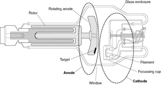
The key components of a modern rotating anode X-ray tube (Fig. 8.1) are:
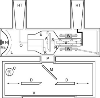
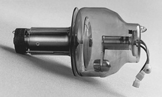
TUBE HOUSING
The tube housing protects the delicate insert from damage during use (Fig. 8.2). It is made of steel or aluminium with an external protective coat of paint to allow easy cleaning and an internal lining of lead to reduce radiation leakage to below the required maximum. The cover has special mounting rings, trunions for attachment to the tube suspension equipment, and sealed terminals and sockets for the high-tension cables and other associated control equipment connections. On the external surface the tube is marked to indicate the position of the focus point of the anode and a plate indicates the electrical characteristics and date of manufacture.
VACUUM ENVELOPE
In order for the X-ray tube to operate, the anode and cathode need to be contained in a vacuum;this vacuum is contained within the tube envelope. The envelope needs to be strong enough to support the anode and cathode assemblies, provide electrical insulation between the two and maintain the vacuum. The tube vacuum envelope is generally made of glass although some high-power tube envelopes are made of metal or ceramic.
FILAMENT ASSEMBLY
The filament is generally made of tungsten as it is:
THE FOCUSSING CUP
The filament is set centrally in a slot machined into a metal focussing cup: the cathode cup.The shape of the cup, along with the electrostatic forces, prevents the electron beam fanning out, concentrating it on the focal spot of the anode (Fig. 8.3).
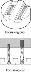
This design is called an electronic lens system with a resulting focal spot width that depends upon:
THE ANODE
The anode is the positive terminal of the X-ray tube; it serves to conduct the tube current, provide support of the target and provides a means ofdissipating the heat away from the target. X-rays are produced by the rapid deceleration of fast moving electrons and tungsten is used as the material of choice for the combination of its properties.
Properties of tungsten
STATIONARY ANODE
The stationary anode tube has a compound anode, which consists of a tungsten target set in a block of copper, the X-rays are produced in the tungsten and the copper conducts the heat away from the target (Fig. 8.4A).
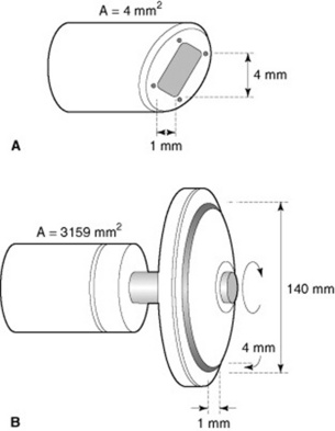
In a stationary anode the X-rays are produced in a small area of the anode (approx. 4 mm2) (Fig. 8.4B), which causes the temperature to rise rapidly; this limits the loading available before damage occurs.
ROTATING ANODE
The rotating anode X-ray tube is a design improvement to allow greater tube loading (Fig. 8.5). The anode is formed as a disc mounted on a rotating stem with the rotational power provided by an induction motor system.
TYPES OF ANODE DISC
A basic anode disc is constructed of a tungsten disc mounted on a rotating stem; however, there are modifications of this basic arrangement designed to increase the heat capacity of the anode. In order to increase this heat capacity there are a variety of compound anode designs available; for example the tungsten track may be sintered onto a molybdenum disc (as molybdenum has a higher heat capacity), which in turn may be backed by a graphite layer providing an increase in heat capacity and a lowering of weight.
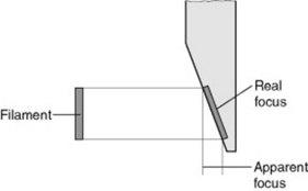
THE LINE FOCUS PRINCIPLE
In order to obtain an X-ray image with the least penumbra the X-rays must be seen to be emanating from as small a point as possible; in theory a point source will provide an image with no penumbra (Fig. 8.6).
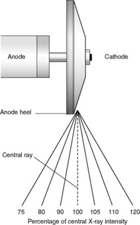
THE ANODE HEEL EFFECT
The X-ray beam is not uniform over its field – there is a gradual decrease in radiation towards the anode end of the tube. As X-radiation is emitted from the target area in a conical shape, measurements have determined that the intensity in the direction of the anode is lower (over and above the difference caused by the inverse square law) than the intensity in the direction of the cathode. The fact that the intensities vary in such a manner causes visible differences in the density produced on the radiographs. This phenomenon is called the ‘heel effect’ (Fig. 8.7).
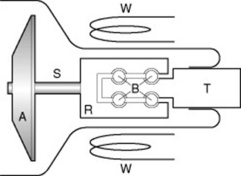
THE STATOR ASSEMBLY
The heat of the anode should be prevented from reaching the stator arrangement. The stem is designed to limit the transfer of heat to the rotor assembly; molybdenum is used as it has lower thermal conductivity than tungsten and is made as thin as possible to reduce heat conduction towards the bearings (Fig. 8.8).
BEAM FILTRATION
The total filtration of an X-ray tube assembly (without any additional added filtration) should be not less than 2.5 mm aluminium equivalent.2 On a number of systems, a facility for introducing additional added filtration into the beam (spectral filtering) is provided within the collimator assembly. The additional added filtration may be aluminium, copper or tantalum and may be introduced manually or automatically.
ANODE COOLING
HEAT PATHWAYS IN A TYPICAL ROTATING ANODE X-RAY TUBE ASSEMBLY
In an X-ray tube the point of maximum heat production is at the focal track or focal spot on the anode. The heat produced in this region has to pass from the tube to the surrounding air in order for the tube not to overheat. The heat produced at the focal spot is carried away by radiation to the glass or metal tube envelope and conduction to the body of the anode where radiation to the metal tube envelope occurs. Conduction away from the anode body is minimised by the stem construction and material to prevent damage to the motor bearings.
Bushong S. Radiologic science for technologists: physics, biology and protection. Elsevier: Mosby, 2004.
Forster E. Equipment for diagnostic radiography. Lancaster, UK: Kluwer Academic, 1985.
A very readable text covering the basis of most syllabi.
Meredith J, Massey J. Fundamental physics of radiology. Oxford: Butterworth-Heinemann, 1984.
A ‘classic’ text still popular after 30 years explores diagnostic and therapy physics.
Stockley S. A Manual of Radiographic Equipment. Edinburgh: Churchill Livingstone, 1986.
A popular text with students, clear diagrams outlining basic ideas.
Wilks R. Principles of radiological physics. Edinburgh: Churchill Livingstone, 1987.
[/level-membership-for-radiology-category][not-level-membership-for-radiology-category]
Chapter 8 The X-ray tube
INTRODUCTION
Since the discovery of X-rays in 1895 by Roentgen and the heated cathode X-ray tube by Coolidge, X-ray tubes have developed into complex pieces of electromechanical engineering. They comprise around 350 parts, taking 150 assembly operations. The cost (at date of publication) can be as much as £20 000.
The key components of a modern rotating anode X-ray tube (Fig. 8.1) are:
TUBE HOUSING
The tube housing protects the delicate insert from damage during use (Fig. 8.2). It is made of steel or aluminium with an external protective coat of paint to allow easy cleaning and an internal lining of lead to reduce radiation leakage to below the required maximum. The cover has special mounting rings, trunions for attachment to the tube suspension equipment, and sealed terminals and sockets for the high-tension cables and other associated control equipment connections. On the external surface the tube is marked to indicate the position of the focus point of the anode and a plate indicates the electrical characteristics and date of manufacture.
VACUUM ENVELOPE
In order for the X-ray tube to operate, the anode and cathode need to be contained in a vacuum;this vacuum is contained within the tube envelope. The envelope needs to be strong enough to support the anode and cathode assemblies, provide electrical insulation between the two and maintain the vacuum. The tube vacuum envelope is generally made of glass although some high-power tube envelopes are made of metal or ceramic.
