The quality of radiographic images and quality assurance
Introduction
The factors that can affect the quality of radiographic images depend on:
The effects of poor radiographic technique are the same whatever type of image receptor is used. These technique errors have already been covered in detail in relation to the three main projections used in dentistry, namely: periapicals (Ch. 9), bitewings (Ch. 10) and panoramic radiographs (Ch. 15).
The creation of the visual digital image was described in Chapter 7, together with how computer software can be used to alter and manipulate the image with regards to contrast, brightness (degree of blackening), magnification, inversion, enhancement and pseudocolourization. Creation of the black/white/grey image on film using chemical processing was also described in Chapter 7. These various images can however be affected by many other factors. This chapter therefore is designed for revision, bringing together and summarizing from earlier chapters all these various factors. It also includes a quick reference section as an aid to fault-finding of film-captured images. Various image faults are illustrated together with their possible causes. This is followed by a section on quality assurance (QA) and suggested quality control measures.
Film-based image quality
As mentioned in Chapter 1, image quality and the amount of detail shown on a radiographic film depends on several factors including:
Characteristics of the X-ray beam
The ideal X-ray beam used for imaging should be:
• Sufficiently penetrating to pass through the patient, to a varying degree, and react with the film emulsion to produce good contrast between the various black, white and grey shadows (see earlier)
• Parallel, i.e. non-diverging, to prevent magnification of the image (see Ch. 3)
• Produced from a point source to reduce blurring of the image margins and the penumbra effect (see Ch. 3).
Image sharpness and resolution
• Geometric unsharpness, including the penumbra effect (see above)
• Motion unsharpness, caused by the patient moving during the exposure
• Absorption unsharpness, caused by variation in object shape, e.g. cervical burn-out at the neck of a tooth (see Ch. 20)
• Screen unsharpness, caused by the diffusion and spread of the light emitted from intensifying screens (see Ch. 4)
• Poor resolution. Resolution, or resolving power of the film, is a measure of the film’s ability to differentiate between different structures and record separate images of small objects placed very close together, and is determined mainly by characteristics of the film including:
Practical factors influencing film-based image quality
As a result of all these variables, film faults and alterations in image quality are inevitable. However, since the diagnostic yield from radiography is related directly to the quality of the image, regular checks and monitoring of these variables are essential to achieve and maintain good quality radiographs. It is these checks which form the basis of quality assurance (QA) programmes.
Typical film faults
Examples of typical film faults are shown below and summarized later in Table 17.1.
Table 17.1
Summary of common film quality problems and their possible causes.
| Reason for rejection | Possible causes | Remedy to each particular fault | |
| General | Particular | ||
| Film too dark | Processing fault (overdevelopment) | Developer concentration too high | Dilute or change chemicals |
| Development time too long | Adjust as necessary | ||
| Developer temperature too high | Adjust as necessary | ||
| Excessive X-ray exposure | Incorrect exposure setting | Adjust and repeat examination | |
| Faulty timer on X-ray set | Arrange service and repair of X-ray set | ||
| Thin patient tissues | Decrease exposure and repeat | ||
| Fogged film | Light leak in darkroom | Check and correct | |
| Faulty safelighting | Inspect safelights visually, coin test, and correct any fault detected | ||
| Old film stock | Discard film | ||
| Poor film storage | Discard film and re-assess storage facilities | ||
| Light leak in cassette | Check hinges and catches and repair or replace if required | ||
| Film too pale | Processing fault (underdevelopment) | Overdiluted developer Inadequate development time |
Change chemicals Adjust as necessary |
| Developer temperature too low | Adjust as necessary | ||
| Exhausted developer | Change chemicals | ||
| Developer contaminated by fixer | Change chemicals | ||
| Inadequate X-ray exposure | Incorrect exposure setting | Adjust and repeat | |
| Faulty timer on X-ray set | Arrange service and repair of X-ray set | ||
| Excessive thickness of patient’s tissues | Increase exposure and repeat | ||
| Inadequate or low contrast | Technique error | Film back to front | Adjust and repeat |
| Processing fault | Overdevelopment (plus dark films) | Check development and time/temperature relationship | |
| Underdevelopment (plus pale films) | As above | ||
| Developer contaminated by fixer | Change chemicals | ||
| Inadequate fixation time (films opaque; milky sheen) | Adjust as necessary | ||
| Fixer exhausted (films opaque; milky sheen) | Change fixer solution | ||
| Fogged film | See above | See above | |
| Unsharp image | Technique error | Patient movement | Assess and instruct patient carefully |
| Excessive bending of the film packet during exposure | Adjust and repeat | ||
| Poor patient positioning (in panoramic radiography) | Greater care in positioning and full use of positioning aids | ||
| Cassette error | Poor film/screen contact | Check cassette and repair or replace if necessary | |
| Incorrect intensifying screen speed | Change screens | ||
| Excessive X-ray exposure | Incorrect exposure setting for thin object causing burn-out | Decrease exposure setting and repeat | |
| Film marked | Handling fault | Film packet bent | Careful handling |
| Careless handling in darkroom | As above | ||
| Processing fault | Chemical spots | Careful chemical handling | |
| Insufficient chemicals to allow full immersion of film | Check chemical tanks and adjust | ||
| Automatic roller marks | Clean processor | ||
| Patient biting too hard on the film | Instruct patient correctly and repeat | ||
| Dirt on intensifying screens | Clean screens regularly | ||
| Poor positioning (Chs 9, 10 and 15) | Film packet incorrectly positioned | Film back to front (plus pale film) | Use film holders for intraoral radiography when possible |
| Not covering area of interest | As above | ||
| Film used twice (plus dark film) | Greater care in film handling | ||
| X-ray tubehead incorrectly positioned | Too steep an angle producing foreshortening | Use beam-aiming devices when possible | |
| Too shallow an angle producing elongation | As above | ||
| Patient incorrectly positioned | Patient incorrectly placed (in panoramic unit) | Greater care in positioning and full use of positioning aids | |
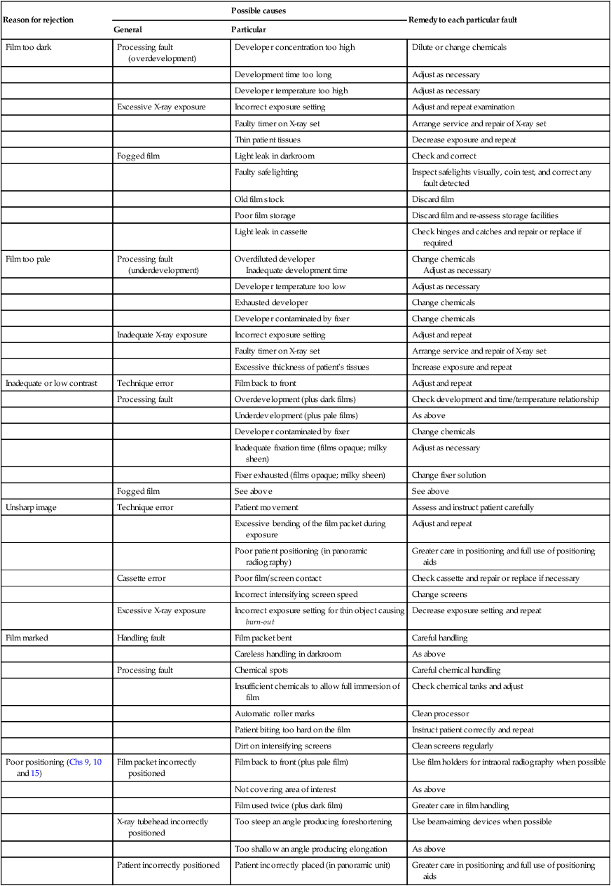
Reproduced, with modifications, from Dental Update with kind permission of Professor K. Horner and George Warman Publications.


Film too pale (Fig. 17.3)
Possible causes
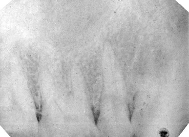
– Faulty X-ray equipment, e.g. timer
– Incorrect exposure time setting by the operator
– Failure to keep timer switch depressed throughout the exposure
– Inadequate time in the developer solution
– Developer solution too dilute


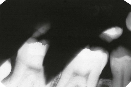
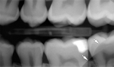
Image unsharp and blurred (Fig. 17.4)
Possible causes
• Movement of the patient during the exposure (see also Chs 9, 10 and 15)
• Excessive bending of the film packet during the exposure (see also Ch. 9)
• Poor film/screen contact within a cassette
• Film type – image definition is poorer with indirect-action film than with direct-action film
• Speed of intensifying screens – fast screens result in loss of detail
• Overexposure – causing burn-out of the edges of a thin object
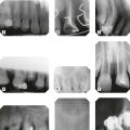
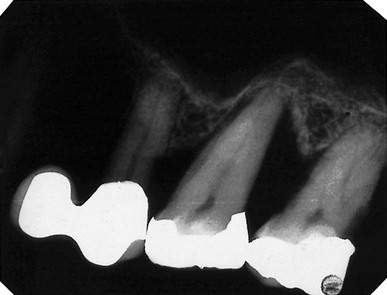
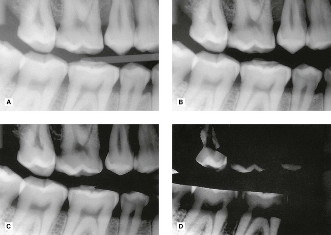
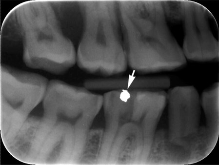
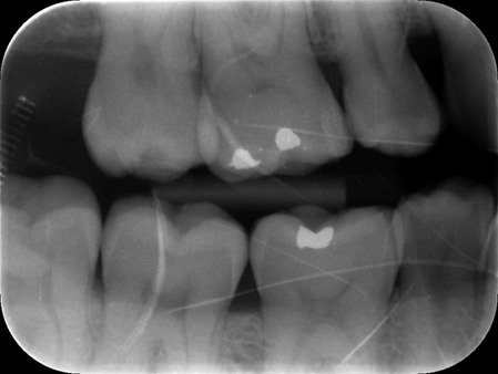
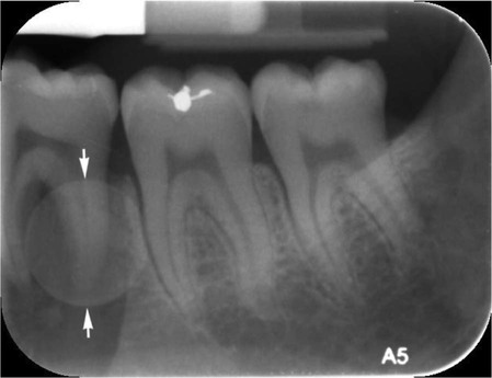
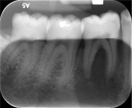
Film marked (Fig. 17.5)
Possible causes
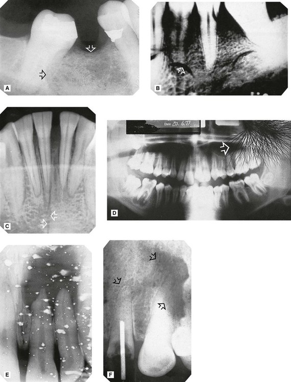
A Fingerprint impression in the emulsion (arrowed).
B Fingernail marks (arrowed).
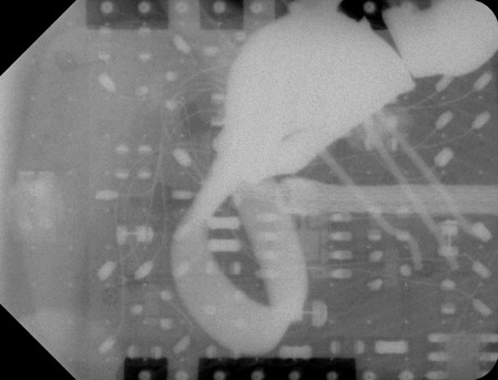
C Sharply bent film (arrowed) damaging the emulsion.
D Discharge of static electricity (arrowed).
E Fixer splashes on the emulsion before the film was placed in the developer.
F Marks (arrowed) caused by residual emulsion remaining following inadequate fixation (these are usually brown).
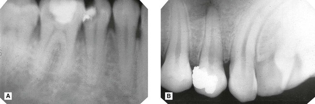
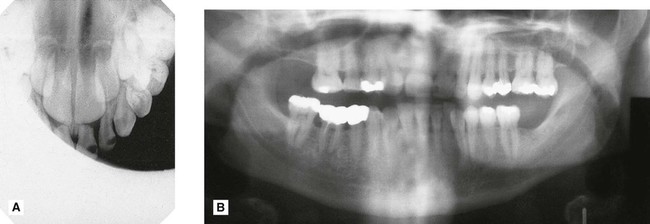
Patient preparation and positioning (radiographic technique) errors (Fig. 17.6)
These errors can happen whatever image receptor is being used and were described in detail and illustrated in Chapters 9, 10 and 15. They are summarized below and can be divided into intraoral and panoramic technique errors.
Intraoral technique errors
• Failure to position the image receptor correctly to capture the area of interest
• Failure to position the image receptor correctly causing it to bend (if flexible) creating geometrical distortion
• Failure to orientate the image receptor correctly and using it back-to front
• Failure to align the X-ray tubehead correctly in the horizontal plane causing:
• Failure to align the X-ray tubehead correctly in the vertical plane causing:
• Failure to instruct the patient to remain still during the exposure with subsequent movement resulting in blurring
• Failure to set correct exposure settings (image too dark or too pale – see earlier)
Panoramic technique errors
• Failure to remove orthodontic appliances
• Failure to remove spectacles
• Inappropriate use of a protective lead apron
• Failure to ensure the spine is straight
• Failure to ensure the incisors are biting on the bite-peg (anteroposterior error)
• Failure to use the light beam markers to ensure mid-sagittal plane is vertical and Frankfort plane is horizontal (horizontal and vertical errors)
• Failure to instruct the patient to press the tongue against the roof of the mouth
• Failure to instruct the patient to remain still throughout the exposure cycle
• Failure to set machine height adjustment correctly
• Failure to set correct exposure settings (image too dark or too pale – see earlier)
Quality assurance in dental radiology
Terminology
The main terms in quality procedures include:
• Quality control – the specific measures for ensuring and verifying the quality of the radiographs produced.
• Quality assurance – the arrangements to ensure that the quality control procedures are effective and that they lead to relevant change and improvement.
• Quality audit – the process of external reassurance and assessment that quality control and quality assurance mechanisms are satisfactory and that they work effectively.
Quality assurance programme
• Implementation should be the responsibility of a named person
• Frequency of operations should be defined
• The content of the essential supporting records should be defined and the frequency for the formal checking of such records.
As stated in the 2001 Guidance Notes and implied by the WHO definition, a well-designed QA programme should be comprehensive but inexpensive to operate and maintain. The standards should be well researched but once laid down would be expected to require only infrequent verification or modification. The procedures should amount to little more than ‘written down common sense’. The aims of these programmes, whether using film-based or digital radiography, can be summarized as follows:
Quality control procedures for film-based radiography
The essential quality control procedures relate to:
• Image quality and film reject analysis
• Patient dose and X-ray equipment
Image quality and film reject analysis
• A day-to-day comparison of the quality of every radiograph to a high standard reference film positioned permanently on the viewing screen and an investigation of any significant deterioration in quality.
• A formal analysis of film quality, either retrospective or prospective, approximately every six months. The 2001 Guidance Notes recommended the simple three-point subjective rating scale shown in Table 17.2, and shown previously in Chapters 9, 10 and 15, be used for film-based intraoral and extraoral radiography.
Table 17.2
| Rating | Quality | Basis |
| 1 | Excellent | No errors of patient preparation, exposure, positioning, processing or film handling |
| 2 | Diagnostically acceptable | Some errors of patient preparation, exposure, positioning, processing or film handling, but which do not detract from the diagnostic utility of the radiograph |
| 3 | Unacceptable | Errors of patient preparation, exposure, positioning, processing or film handling, which render the radiograph diagnostically unacceptable |
• Based on these quality ratings, performance targets can be set. Suitable targets recommended in the Guidance Notes are shown in Table 17.3 with the advice that practices should aim to achieve these targets within three years of implementing the QA programme. The ‘interim targets’ should be regarded as the minimum achievable standard in the shorter term.
Table 17.3
Minimum and interim targets for radiographic quality from the 2001 Guidance Notes*
| Rating | Target | Interim target |
| 1 | Not less than 70% | Not less than 50% |
| 2 | Not greater than 20% | Not greater than 40% |
| 3 | Not greater than 10% | Not greater than 10% |
• Analysis of all unacceptable films given a rating of 3, sometimes referred to as film reject analysis (see below).
Film reject analysis
• Nature of the film fault/error, as shown earlier, e.g.:
• Known or suspected cause of the error or fault and corrective action taken (see Table 17.1)
• Number of repeat radiographs (if taken)
• Total number of radiographs taken during the same time period. This allows the percentage of faulty films to be calculated.
Patient dose and X-ray equipment
• An initial critical examination and report – carried out by the installer
• An acceptance test – carried out by a radiation protection adviser/medical physicist before equipment is brought into clinical use, which should include measurement of patient dose
• A re-examination report following any relocation, repair or modification of equipment that may have radiation protection implications
• Regular checks of important features that could affect radiation protection including:
– Correct functioning of warning lights and audible alarms
– Correct operation of safety devices
– Satisfactory performance of the counterbalance for maintaining the correct position of the tubehead
– Correct alignment of the beam collimation
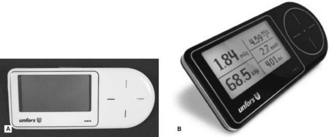
– X-ray equipment output. This can be performed in dental practice using one of the recently developed devices shown in Fig. 17.7.
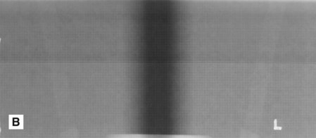
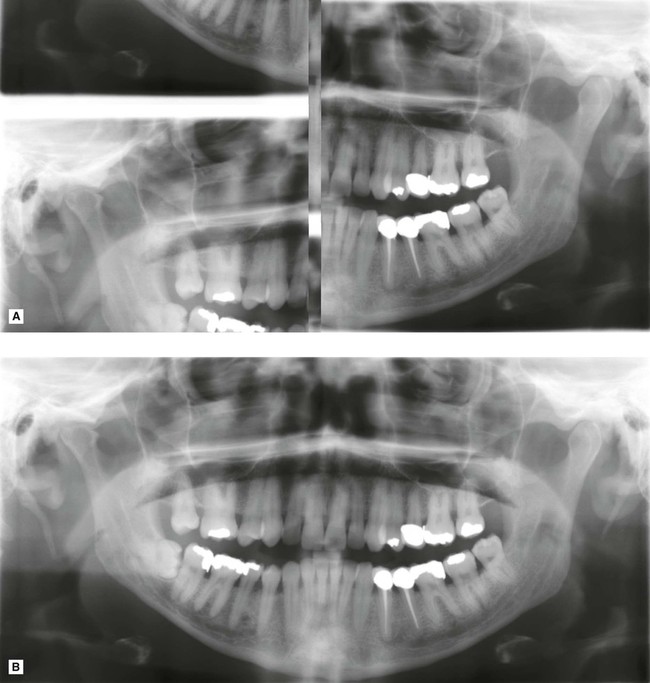
• Checks on panoramic equipment regarding reproducibility, uniformity, beam alignment and synchronization of the exposure with tube motion. For example, the following simple test could be carried out in dental practice, based broadly on the IPEM Report 91(2005)
1. On installation of the equipment a baseline image is created by placing a 1 mm thick copper strip over the X-ray port (to filter the beam), and exposing a cassette containing a film using a standard adult panoramic exposure
2. The test is repeated every 1–3 months and the subsequent images compared to the baseline image and assessed for reproducibility, uniformity beam alignment and synchronization:
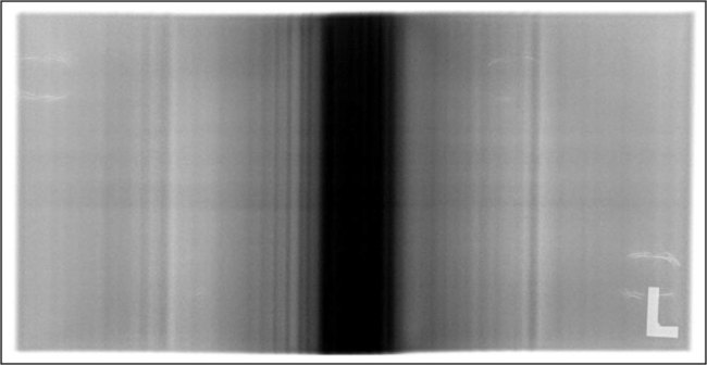
• Reproducibility and uniformity – the image should be of similar density to the baseline image and there should be no areas of non-uniformity. There will always be a vertical dark central band present on a panoramic image, due to higher exposure factors being used at this point in the panoramic cycle for extra penetration of the cervical spine. Any other vertical banding may indicate a fault in the exposure or the rotation system, as shown in Fig. 17.8.
• Beam alignment and synchronization – the radiation field area should lie completely within the edges of the image receptor.
• Written records and an equipment log should be maintained and include:
– All installer’s formal written reports describing the checks made, the results obtained and action taken
• An up-to-date inventory of each item of X-ray equipment should be maintained, and available, at each practice and contains:
• Compliance with any national medical physics recommendations, for example in the UK the Recommended Standards for the Routine Performance Testing of Diagnostic X-ray Imaging Systems, Report 91 of the Institute of Physics and Engineering in Medicine (IPEM), published in 2005.
Darkroom, image receptors and processing
Darkroom
• General cleanliness (daily), but particularly of work surfaces and film hangers (if used)
• Light-tightness (yearly), by standing in the darkroom in total darkness with the door closed and safelights switched off and visually inspecting for light leakage
• Safelights (yearly), to ensure that these do not cause fogging of films. Checks are required on:
– Type of filter – this should be compatible with the colour sensitivity of film used, i.e. blue, green or ultraviolet (see Ch. 6)
– Condition of filters – scratched filters should be replaced
– Wattage of the bulb – ideally it should be no more than 25W
– Their distance from the work surface – ideally they should be at least 1.2 m (4 ft) away
– Overall safety (i.e. their fogging effect on film) – the simple quality control measure for doing this is known as the coin test:
1. Expose a piece of screen film in a cassette to a very small even exposure of X-rays (so-called flash exposure) to make the emulsion ultra-sensitive to subsequent light exposure
2. In the darkroom, remove the film from the cassette and place on the worksurface underneath the turned-off safelight
3. Place a series of coins (e.g. nine) in a row on the film and cover them all with a piece of card
4. Turn on the safelight and then slide the card to reveal the first coin and leave for approximately 30 seconds
5. Slide the card along to reveal the second coin and leave again for approximately 30 seconds
An example of the coin test is shown in Fig. 17.9. Fogging (blackening) of the film owing to the safelight will then be obvious when compared to the clear area protected by the coin. The part of the film adjacent to the first coin will have been exposed to the safelight for the longest time and will be the darkest. In practice, the normal film-handling time under the safelight can be measured and the effect of safelight fogging established.
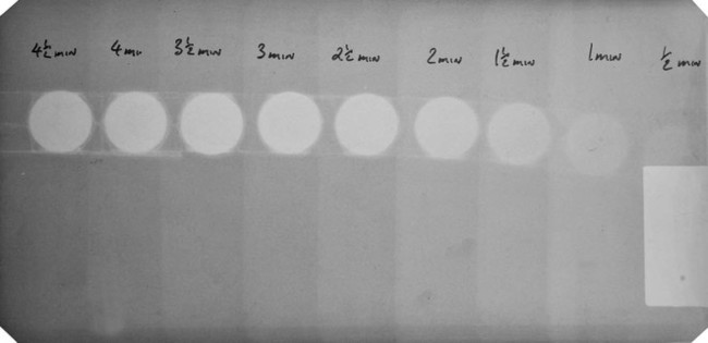
Image receptors
Cassettes
• Regular cleaning of intensifying screens with a proprietary cleaner
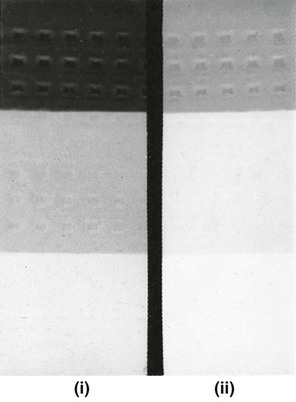
• Regular checks for light-tightness, as follows:
1. Load a cassette with an unexposed film and place the cassette on a window sill in the daylight for a few minutes
2. Process the film – any ingress of light will have fogged (darkened) the film (see Fig. 17.10A)
 />
/>
• Regular checks for film/screen contact, as follows:
1. Load a cassette with an unexposed film and a similar-sized piece of graph paper
2. Expose the cassette to X-rays using a very short exposure time
3. Process the film – any areas of poor film/screen contact will be demonstrated by loss of definition of the image of the graph paper (see Fig. 17.10B)
• A simple method of identification of films taken in similar-looking cassettes, e.g. a Letraset letter on one screen.
Processing
The QA programme should contain written instructions about each of the following:
Chemical solutions
• Always made up to the manufacturers’ instructions taking special precautions to avoid even trace amounts of contamination of the developer by the fixer, e.g. always fill the fixer tank first so that any splashes into the developer tank can be washed away before pouring in the developer
• Always at the correct temperature
• Changed or replenished regularly – ideally every 2 weeks – and records should be kept to control and validate these changes
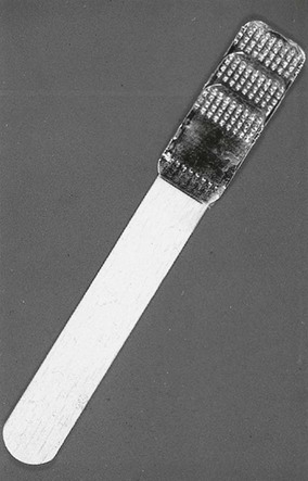
• Monitored for deterioration. This can be done easily using radiographs of a step-wedge phantom:
1. Make a simple step-wedge phantom using the lead foil from inside intraoral film packets, as shown in Fig. 17.11).
2. Radiograph the step-wedge using known exposure factors
3. Process the film in fresh solutions to produce a standard reference film
4. Repeat, using the same exposure factors, every day as the solutions become exhausted
5. Compare each day’s film with the standard reference film to determine objectively any decrease in blackening of the processed film, which would indicate deterioration of the developer (see Fig. 17.12)
Processing equipment
• Manual processing requires the use of accurate timers, thermometers and immersion heaters. Instructions on their proper use should be provided.
• Automatic processors require regular replenishment of chemical solutions and regular cleaning, especially of the rollers. All cleaning procedures should be written down, including how often they should be carried out.
• A record log confirming that all cleaning procedures have been carried out should be kept.
Working procedures
• Local rules – required in the UK under the Ionising Radiations Regulations 1999. These rules should contain the procedural and operational elements that are essential to the safe use of X-ray equipment, including guidance on exposure times, and as such should contain much of what is relevant to the maintenance of good standards in QA.
• Employers’ written procedures – required in the UK under the Ionising Radiation (Medical Exposure) Regulations 2000.
• Operational procedures or systems of work – these include written procedures that provide for all actions that indirectly affect radiation safety and diagnostic quality, e.g. instructions for the correct preparation and subsequent use of processing chemicals (as explained earlier).
• Procedures log – the QA programme should include the maintenance of a procedures log to record the existence of appropriate Local Rules and Employers’ Written Procedures, together with a record of each occasion on which they are reviewed or modified (ideally every 12 months).
Digital image quality
• Subject contrast – the black/white and grey difference in the visual caused by different degrees of attenuation as the X-ray beam is transmitted through different parts of the patient’s tissues and dependent upon:
– Differences in tissue thickness
– Differences in tissue density
• Image geometry – the geometric accuracy of any image depends upon the position of the X-ray beam, object and image receptor satisfying certain basic geometrical requirements:
– The object and the digital image receptor should be in contact or as close together as possible
– The object and the digital image receptor should be parallel to one another
– The X-ray tubehead should be positioned so that the X-ray beam meets both the object and the digital image receptor at right angles
• Characteristics of the X-ray beam – the beam should be:
– Sufficiently penetrating to pass through the patient, to a varying degree, to interact differentially with the digital image receptor (solid-state or phosphor plate) to produce a good contrasted black/white/grey image
– Parallel, i.e. non-diverging, to prevent magnification of the image (see Ch. 3)
– Produced from a point source to reduce blurring of the image margins and the penumbra effect (see Ch. 3)
• Type of digital image receptor – solid-state or phosphor plate and their resolution and ability to define image sharpness (see Ch. 4)
Practical factors influencing digital image quality
• The image receptor – solid-state or phosphor plate
• Image processing and manipulation using computer software (see Ch. 5)
As a result of all these variables, digital image faults and alterations in digital image quality are inevitable and not all these faults can be corrected by manipulating the image using image enhancement software, as described in Chapter 5. QA programmes are still required.
Typical digital image faults
Examples of some typical digital image faults, other than those as a result of poor radiographic technique described in Chapters 9, 10 and 15, are shown below.
Quality control procedures for digital radiography
Those QA procedures specifically relevant to digital imaging, including digital image quality assessment and digital equipment, are described below.
Digital image quality assessment and image reject analysis
This assessment should include:
• Investigation of any significant deterioration in quality and instigation of appropriate corrective action
• Recording all investigations together with the identified cause of deterioration and the action taken
• Regular annotation (approx. every 3 months) of the image quality record to indicate that the day-to-day checks have been carried out and, where appropriate, that no significant deterioration in image quality has been observed
• Subjective assessment of the quality of each radiograph. The NRPB/DoH’s 2001 guidelines recommended a simple three-point scale for film that can be used but the basis of the decision needs to be amended (Table 17.4).
Table 17.4
Suggested subjective quality rating criteria for digitally captured images
| Rating | Quality | Basis |
| 1 | Excellent | No errors of patient preparation, positioning or digital receptor handling |
| 2 | Diagnostically acceptable | Some errors in patient preparation, positioning or digital receptor handling but which do not detract from the diagnostic utility of the image |
| 3 | Unacceptable | Errors of patient preparation, positioning, digital receptor handling or exposure (which cannot be corrected by computer software) which render the image diagnostically unacceptable |
All images should be assessed in this way and the results recorded so that the overall quality of radiography can be evaluated and measured against the NRPB/DoH targets (see Table 17.3).
Image reject analysis
Digital equipment
Solid-state sensors
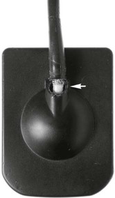
• Regular checks to ensure no evidence of cracks or damage to the cable and sensor casing (see Fig. 17.21)
Phosphor plates
• Regular checks for visible scratches and dirt (see Figs 17.22)
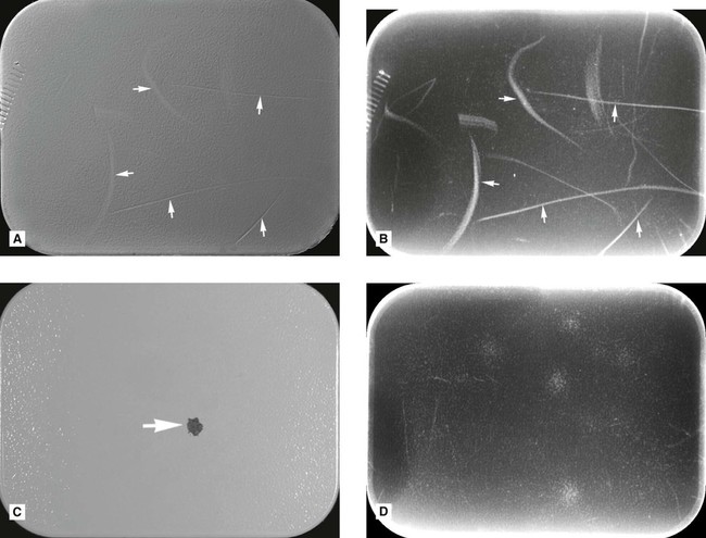
• Being passed daily through the reader to detect scratches (see Fig. 17.22)
• Regular cleaning following the manufacturer’s instructions
• Regular assessment for non-uniformity of receptor (see Fig. 17.22).
Monitors
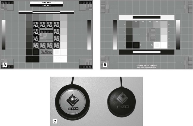
• Regular QA calibration/checks for distortion, grey scale reproduction, limiting resolution (at both high and low contrast) and uniformity. This can be done using specific test patterns designed for this purpose such as the Technical Group 18 QC (TG18-QC) test pattern produced by the American Association of Physicists in Medicine, as shown in Fig. 17.23A or the SMPTE test pattern designed by the Society of Motion Pictures and Television Engineers, as shown in Fig. 17.23B. Alternatively, specifically designed QA calibration tools and software can be used, as shown in Fig. 17.23C.