4
The ECG When the Patient has a Bradycardia
MECHANISM OF BRADYCARDIAS
The causes of sinus bradycardia have been discussed in Chapter 1 (see Box 1.2, p. 5). Escape rhythms have been discussed in Chapter 2 (p. 82 ) . They are usually asymptomatic, but symptoms occur when the automaticity that generates the escape rhythm is inadequate to maintain a cardiac output. A bradycardia may cause the symptom of syncope; some of the possible underlying causes are listed in Box 4.1.
SINOATRIAL DISEASE – THE ‘SICK SINUS SYNDROME’
Disordered SA node function can be familial or congenital and can occur in ischaemic, rheumatic, hypertensive or infiltrative cardiac disease. It is, however, frequently idiopathic. Abnormal function of the SA node may be associated with failure of the conduction system. Many patients with sinoatrial disease are asymptomatic, but all the symptoms associated with bradycardias – dizziness, syncope and the symptoms of heart failure – can occur. Atrial and junctional tachycardias often occur together with sinus node dysfunction, when the patient may present with palpitations.
The abnormal rhythms seen in the sick sinus syndrome are listed in Box 4.2.
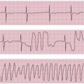
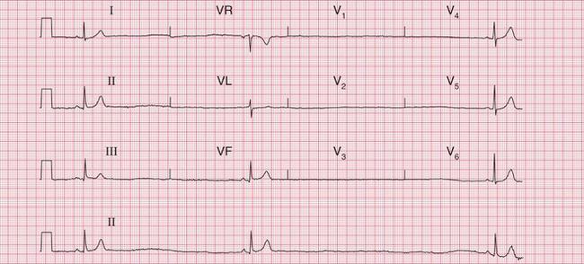
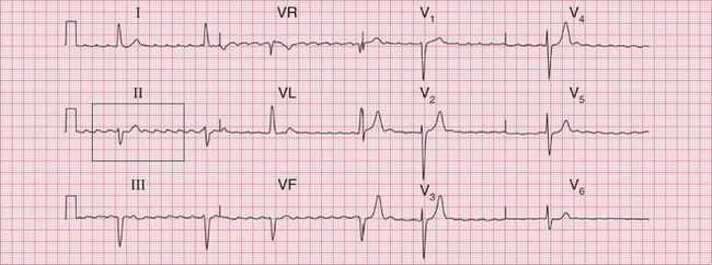
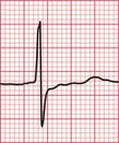
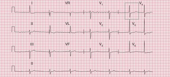
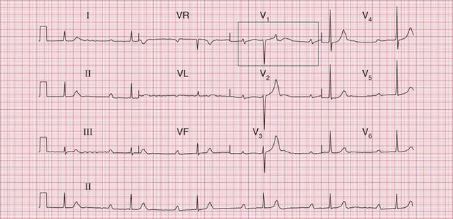
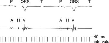
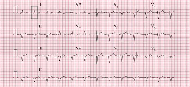
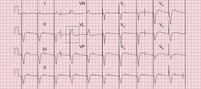
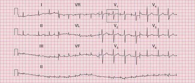
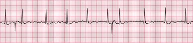
The ECGs in Figures 4.1 and 4.2 are from a young man who had a normal ECG with a slow sinus rate when asymptomatic, but intermittently became extremely dizzy when he developed a profound sinus bradycardia.
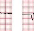
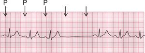
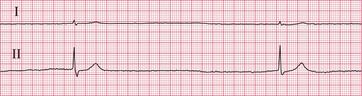
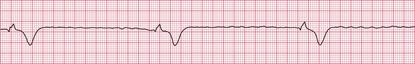
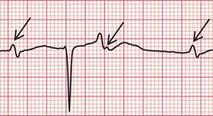
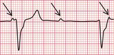
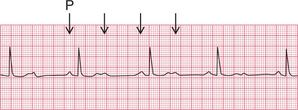
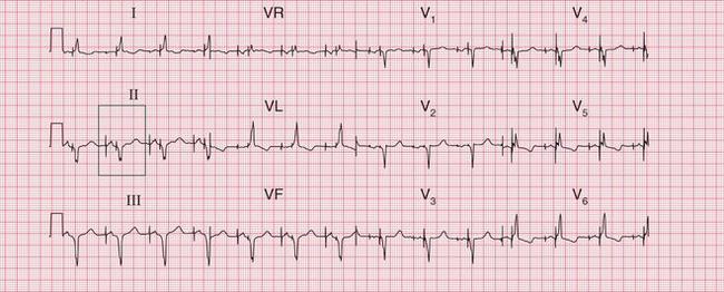
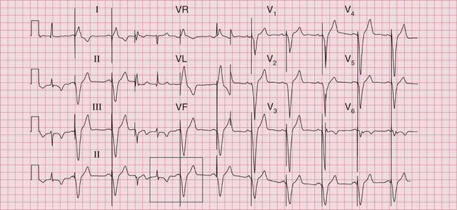
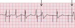
The ECG in Figure 4.3 shows an ambulatory record from a young woman who complained of short-lived attacks of dizziness. When she had these, the ECG showed sinus pauses.
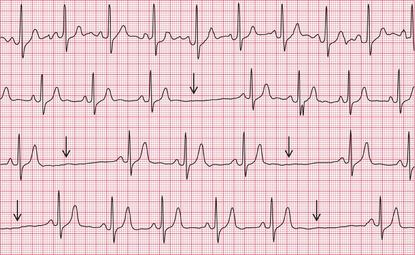
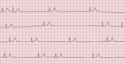
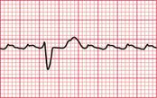
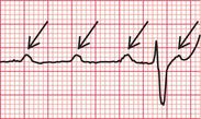
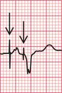
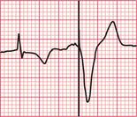
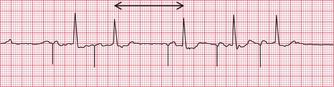
Figure 4.4 shows the other variety of sinus pause – sinus arrest.
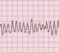
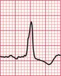
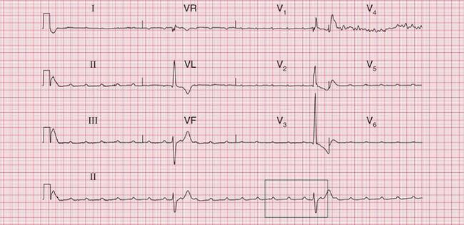
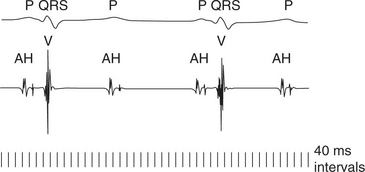
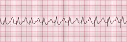
The ECG in Figure 4.5 shows an example of a ‘silent atrium’, when the heart rhythm depends on the irregular depolarization of a focus in the AV node.
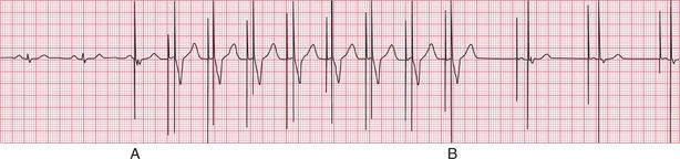
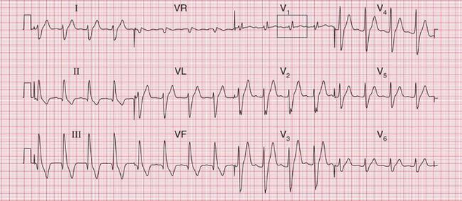
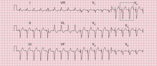
The combination of sick sinus syndrome and episodes of tachycardia is sometimes called the ‘bradycar- dia-tachycardia syndrome’ and Figure 4.6 shows the rhythm of a patient with this syndrome. This patient was asymptomatic at times, when his ECG showed a ‘silent atrium’ with a slow and irregular junctional (AV nodal) escape rhythm, but he complained of palpitations when he had an AV nodal tachycardia.
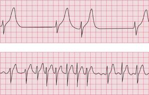
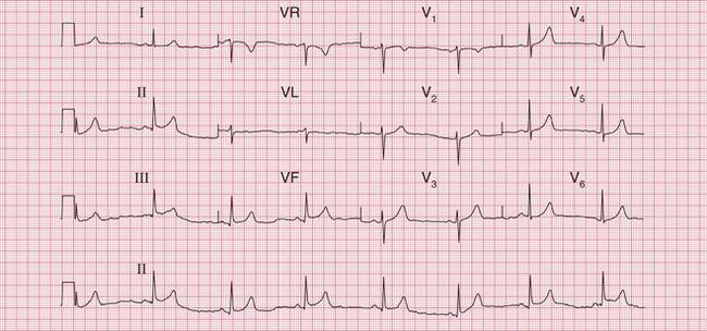
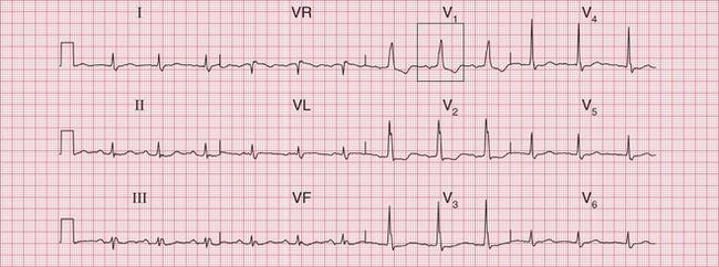
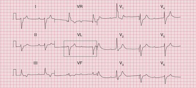
Figure 4.7 shows the ECG from a patient who, when asymptomatic, showed first degree block and right bundle branch block. He complained of fainting attacks, and an ambulatory recording showed that this was due to sinus arrest with a very slow AV nodal escape rhythm, giving a ventricular rate of 15/min ( Fig. 4.8, p. 177). This is an example of the combination of conduction system disease and sick sinus syndrome.
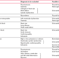
Possible causes of sick sinus syndrome are listed in Box 4.3.
ATRIAL FIBRILLATION AND FLUTTER
A slow ventricular rate can accompany atrial flutter or atrial fibrillation because of slow conduction through the AV node and His bundle systems ( Figs 4.9 and 4.10). This may be the result of treatment with drugs that delay AV nodal conduction, such as digoxin, beta- blockers or verapamil, but can occur because of conducting tissue disease.
Complete block associated with atrial fibrillation is recognized from the regular and wide QRS complexes which originate in the ventricular muscle ( Fig. 4.11).
ATRIOVENTRICULAR BLOCK
Symptoms are not caused by first degree block, second degree block of the Wenckebach or Mobitz type 2 varieties, left anterior hemiblock or the bundle branch blocks.
Second degree block of the 2:1 or 3:1 type will cause dizziness and breathlessness if the ventricular rate is slow enough ( Fig. 4.12). Young people tolerate slow hearts better than old people do.
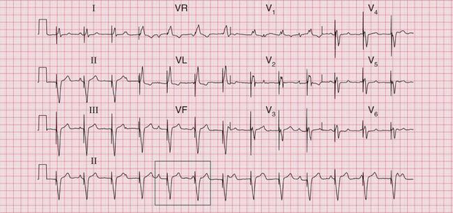
Complete (third degree) block characteristically involves a slow rate, but this may be fast enough to cause only tiredness or the symptoms of heart failure. Figure 4.13 shows the ECG of a 60-year-old man who, despite a heart rate of 40/min, had few complaints.
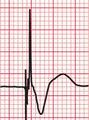
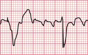
If the ventricular rate is very slow the patient may lose consciousness in a ‘Stokes-Adams’ attack, which can cause a seizure and sometimes death. The ECG in Figure 4.14 is from a patient who was asymptomatic while his ECG showed sinus rhythm with first degree block and right bundle branch block, but who then had a Stokes-Adams attack with the onset of complete block ( Fig. 4.15).

The possible causes of heart block are summarized in Box 4.4.
THE ENDOCARDIAL ECG IN ATRIOVENTRICULAR BLOCK
The ordinary surface ECG provides all the information necessary for the identification of heart block, but the spread of excitation through the heart can be seen more accurately from an intracardiac recording.
The endocardial ECG used during electrophysiologi- cal studies simultaneously displays depolarizations recorded from several catheters, passed percutaneously via a vein in to the heart. Each catheter has multiple electrodes (see Fig. 3.56), which show the timing of depolarization through the heart ( Fig. 4.16). The components of the wave of depolarization are best illustrated from recordings taken by the His catheter. The ‘A’ wave of atrial depolarization (the P wave of the surface ECG) is normally followed by the sharp deflection of the ‘H’ spike, caused by the depolarization of the His bundle. The AH interval is 55-120 ms in normal subjects, with most of this period being due to delay within the AV node. The ‘V’ wave normally follows, representing ventricular depolarization (the QRS complex of the surface ECG). The HV interval (normal range 33-35 ms) measures the time taken for depolarization to spread from the His bundle to the first part of the interventricular septum.
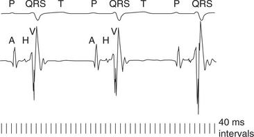
Figure 4.17 shows an endocardial ECG from a patient with first degree heart block, in this case due to prolongation of the AH interval.
A His bundle electrogram also demonstrates the site of second degree block. In the case of 2 : 1 block, this is usually in the His bundle rather than the AV node. Therefore a normal H (or His) spike will be seen, but in the nonconducted beats the H spike will not be followed by a V wave ( Figs 4.18 and 4.19).
MANAGEMENT OF BRADYCARDIAS
Bradycardias must be treated if they are associated with hypotension, poor peripheral perfusion, or escape arrhythmias. Any bradycardia can be treated with:
• Atropine 600 μg i.v., repeated at 5 min intervals to a total 1.8 mg. Note: Overdose causes tachycardia, hallucinations and urinary retention.
• Isoprenaline 1-4 μg/min. Note: Overdose causes ventricular arrhythmias which are difficult to treat. An isoprenaline infusion should only be used while preparations are being made for pacing.
TEMPORARY PACING IN PATIENTS WITH ACUTE MYOCARDIAL INFARCTION
PERMANENT PACING
PACING
An electrical pulse is generated between an electrical pole at the tip of the pacing lead and either a second pole more proximally within the pacing lead (bipolar lead) or the pacemaker box itself (unipolar lead). This causes depolarization of the surrounding myocardium, the propagation of an action potential from this focus and the contraction of the paced cardiac chamber. This process is repeated at a basal rate determined when the pacemaker is programmed, although it can be suppressed as a result of device sensing (see below).
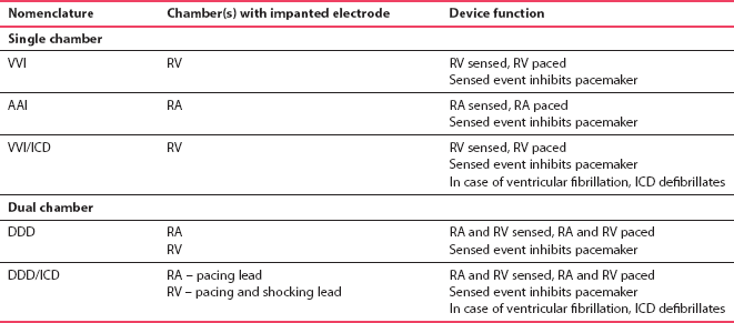
PACEMAKER NOMENCLATURE
The letters of the NBG Code signify the following:
• the first letter describes the chamber(s) paced (A, V or D)
• the second letter describes the chamber(s) sensed (A, V, D or 0)
• the third letter describes the response to a sensed event (I, D or 0)
• a fourth letter (R) is used when the rate modulation is programmable.
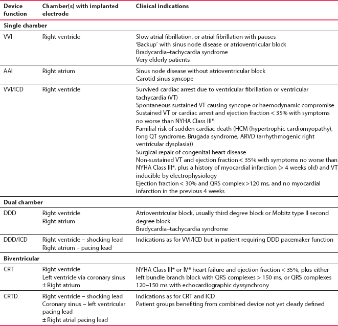
The most commonly used types of pacemaker are listed in Table 4.1.
RIGHT VENTRICULAR PACEMAKERS (VVI)
One of the most common types of pacemaker, these have a single lead implanted in the right ventricle, usually at the apex ( Fig. 4.20). The lead senses electrical activity in the right ventricle and, if no spontaneous cardiac activity is sensed, paces the ventricle after a predetermined interval. Note that unipolar and bipolar pacing leads cannot easily be differentiated on a routine chest X-ray. The indications for VVI pacing are listed in Box 4.5.
ECG APPEARANCE
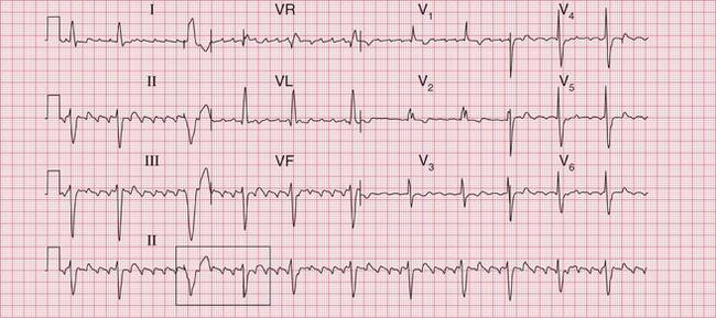
With bipolar right ventricular pacing, the ECG is characterized by a pacing spike followed by a broad QRS complex of left bundle branch block morphology, because cardiac depolarization originates from the lead tip in the right ventricle ( Fig. 4.21). The pacing spikes vary in size and morphology in different ECG leads and in different patients, and may not be visible in all leads.

With unipolar pacing, in which the electrical circuit is between the lead tip and the pacemaker box, the pacing spike is very large compared to that associated with bipolar pacing, in which the poles are close together ( Fig. 4.22).
If the pacemaker senses spontaneous cardiac activity, pacing will be suppressed for a predetermined time interval. The ECG will then show intermittent pacing, with varying amounts of paced ventricular rhythm and underlying ventricular rhythm ( Figs 4.23 and 4.24).
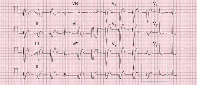
The underlying atrial rhythm can be determined from the ECG, and may be important for clinical decisions, such as anticoagulation. There may be sinus rhythm, atrial fibrillation, atrial flutter ( Fig. 4.24) or complete block ( Fig. 4.25).
RIGHT ATRIAL PACEMAKERS (AAI)
This is a rarely used mode of pacing, with a single lead implanted in the right atrium, usually in the atrial appendage ( Fig. 4.26). This type of pacing senses spontaneous activity in the right atrium, and paces if the sinus node rate falls below a predetermined level.
The indications for AAI pacing are summarized in Box 4.6.
ECG APPEARANCE
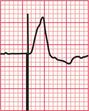
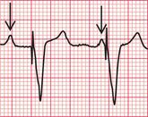
With atrial pacing the ECG is characterized by a pacing spike followed by a paced P wave. The PR interval and QRS complex are usually normal, indicating no AV node disease ( Fig. 4.27).

DUAL-CHAMBER PACEMAKERS (DDD)
DDD pacemakers are frequently used devices with two leads, one implanted in the right atrium and one in the right ventricle ( Fig. 4.28).
Dual-chamber pacing is appropriate with the conditions listed in Box 4.7.
ECG APPEARANCE
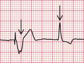
When both the atrium and the ventricle are being paced, an atrial pacing spike is followed by a paced P wave, then a ventricular pacing spike is followed by a paced ventricular beat ( Fig. 4.29).
When the intrinsic atrial rate exceeds the threshold for atrial pacing, ‘atrial tracking’ occurs. Atrial sensing takes place, but the intrinsic PR interval is longer than the programmed AV delay – leading to ventricular pacing. The ECG shows no atrial pacing spikes, but shows spontaneous P waves followed by ventricular pacing spikes and paced ventricular beats ( Fig. 4.30).
Atrial pacing with ventricular tracking would be an unusual but theoretically possible situation. It would occur if the intrinsic atrial rate was slower than the threshold for atrial pacing, but the PR interval was shorter than the programmed AV delay. Hence there would be atrial pacing and intrinsic QRS complexes. The ECG would show atrial pacing spikes, paced P waves and spontaneous conducted ventricular beats.
In intermittent pacing, spontaneous atrial or ventricular activity will be sensed – leading to the inhibition of pacing in that chamber. If the programmed maximum PR interval is not exceeded, sensed atrial contraction may be followed by an AV conducted beat and a sensed QRS complex. The ECG will then show some intrinsic rhythm and some intermittent pacing ( Fig. 4.31).
ABNORMAL PACEMAKER FUNCTION
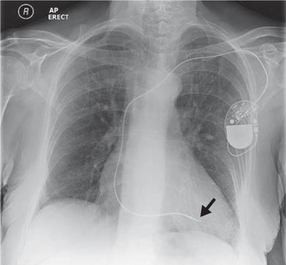
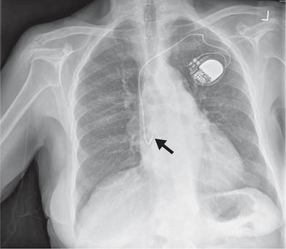
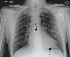
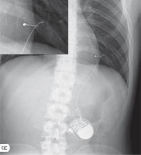
Pacemaker failure is rare. Most failures are due to problems with the pacing and/or sensing functions of the device. Complete diagnosis will usually require remote interrogation of the pacemaker, by placing over the implanted device a wand or header connected to a specialist programmer. This reveals information about how the device has been performing, as well as assessment of the leads and pacemaker function. There are various potential causes of device failure. Early after implantation, lead displacement may occur ( Fig. 4.32). Rarer causes include lead insulation failure or lead fracture ( Fig. 4.33). Unexpected battery depletion is rare, because devices are usually monitored regularly.
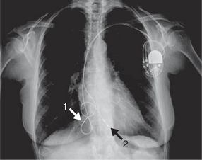
Fig. 4.32 Chest X-ray showing right atrial and ventricular lead displacement
Note
FAILED PACING CAPTURE
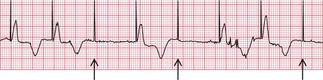
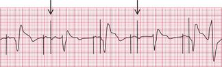
This occurs when the voltage delivered to the pacemaker lead fails to trigger myocardial depolarization. It is characterized by the presence of pacing spikes but no subsequent atrial or ventricular depolarization ( Figs 4.34 and 4.35).
UNDER-SENSING
‘Under-sensing’ occurs when the device develops an inability to detect intrinsic cardiac activity, and thus fails to suppress pacing in response to an intrinsic beat. The ECG is characterized by the presence of paced and normal beats closer together than would be expected from the programmed interval ( Figs 4.36 and 4.37).
OVER-SENSING OR FAR-FIELD SENSING
This arises when sensing occurs in the absence of real intrinsic cardiac activity, triggering the inappropriate suppression of pacing. The ECG is characterized by inappropriately long intervals between beats, when pacing would be expected ( Fig. 4.38).
PACEMAKER-MEDIATED TACHYCARDIA
A rare problem occurs when ventricular pacing triggers retrogradely conducted atrial depolarization, which is then sensed and triggers further ventricular pacing at an inappropriately short interval ( Fig. 4.39). Pacemakers have a function for preventing this, called PVARP (post-ventricular atrial refractory period). This is a refractory period after ventricular pacing, in which atrial activity cannot be sensed. Inappropriately rapid pacing will require specialist assessment.
MAGNET RATE
A simple check of pacemaker function can be made by applying a magnet to the skin over the device. This will trigger obligate pacing at the ‘magnet rate’ ( Fig. 4.40). Pacing spikes will be delivered at this fixed preset rate regardless of the intrinsic rhythm, and should cause depolarization unless delivered at the time of an intrinsic beat, when fusion may occur. The pacemaker will return to normal programmed function when the magnet is removed.