Synthetic Midurethral Slings for the Correction of Stress Incontinence
Mickey M. Karram  Apurva B. Pancholy
In 1996, Ulmsten et al introduced the first synthetic midurethral sling, which they named the tension-free vaginal tape (TVT) procedure. This procedure introduced the concept of placing a synthetic material (polypropylene) under the midportion of the urethra in a tension-free fashion. The technique quickly gained popularity because it involved minimal vaginal dissection, was easy to learn, and could be performed with the patient under local anesthesia on an outpatient basis. To date several studies have compared the TVT procedure with more traditional retropubic procedures such as the Burch colposuspension and have shown equal to superior cure rates with less morbidity. The success of the original TVT midurethral sling has led to the development of other midurethral slings in an effort to decrease morbidity while maintaining efficacy. In 2001, Delorme described the first transobturator synthetic midurethral sling. The motivation behind the development of this approach was to reduce the risk of bladder perforation and eliminate the risk of bowel or major blood vessel injury, which had been reported with the TVT procedure. Subsequent studies have shown that a transobturator midurethral sling is as efficacious as a retropubic synthetic midurethral sling, if the patient does not have intrinsic sphincter deficiency. More recently, single-incision midurethral slings have been described. The newest version of a polypropylene sling requires only one incision in the vagina because the sling has no exit points. This chapter discusses anatomy and currently recommended techniques for the placement of these various synthetic midurethral slings.
Retropubic Synthetic Midurethral Slings
The tension-free vaginal tape procedure was the first retropubic synthetic midurethral sling. This ambulatory procedure aims to restore the pubourethral ligament and suburethral vaginal hammock by using specially designed needles attached to a synthetic sling material (Fig. 58–1). The synthetic sling material is made of polypropylene and is approximately 1 cm wide × 40 cm in length. This sling material is attached to two stainless steel needles, which are passed on each side of the urethra blindly through the retropubic space. The needles exit through a previously created stab wound in the suprapubic area. Because this type of sling requires blind passage of a needle through the retropubic space, it is imperative that the surgeon have a clear understanding of the important anatomic structures of the retropubic space, to avoid potential complications (Figs. 58–2 through 58–5). Besides the potential for damaging the urethra or the bladder, there is also potential for injuring important vascular structures, including the obturator neurovascular bundle and the external iliac vessels as they exit the pelvis (see Figs. 58–2 through 58–5).
The technique for placement of a retropubic synthetic midurethral sling is as follows:
1. The procedure can be performed with the patient under local, regional, or general anesthesia. If local anesthesia is used, a combination of an anesthetic and a vasoconstrictive agent is usually injected into the abdominal skin just above the pubic symphysis and downward along the back of the pubic bone into the space of Retzius. A small suprapubic incision is made on each side medial to the pubic tubercle at the superior pubic ramus of the pubic bone (Fig. 58–6).
2. Even if the procedure is performed with the patient under general or regional anesthesia, the anterior vaginal wall is always hydrodissected with an anesthetic solution before the incision is made. A midline anterior vaginal wall incision is made at the level of the mid to distal urethra. It should be noted that this area of the vagina is fused to the posterior urethra. This vaginal wall must be sharply separated from the underlying urethra (Fig. 58–7).
3. With Metzenbaum or Mayo scissors, two tunnels are created through the tissue to the level of the inferior pubic ramus on each side. The direction of the tips of the scissors should be toward the ipsilateral shoulder. The tunnel needs to be only large enough to admit the 5-mm TVT needle (see Fig 58–7).
4. The needle is then brought into the field and is attached to a nondisposable handle. The tip of the needle is placed in the tunnel so it is pointing toward the ipsilateral shoulder. The dominant hand holds the handle, and the index finger of the nondominant hand is placed in the anterior vaginal wall with the thumb placed on the back of the disposable needle (Fig. 58–8). In this way, the appropriate tension required to penetrate the urogenital diaphragm with the needle is best appreciated. Once the tip of the needle has penetrated the urogenital diaphragm, the handle should be dropped in an inferior direction, and the tip of the needle moved medially and superiorly so that it hugs the back of the pubic bone (Fig. 58–9). The needle is then advanced to the posterior aspect of the rectus muscle and penetrates up through the anterior abdominal fascia to exit from the previously created suprapubic stab wound.
5. With the needle in place, cystoscopy is performed with a 70° cystoscope to ensure that no inadvertent penetration of the needle through the bladder occurs. During cystoscopy, it is important to aggressively distend the bladder so that any subtle indentations or penetrations from the needle will be visualized (Fig. 58–10). The needle is then withdrawn through the stab incision, and the same procedure is repeated exactly on the opposite side. In this way, the Prolene tape covered by a plastic sheath is placed in a U shape around the urethra (Figs. 58–11 and 58–12). The technique utilized to determine the appropriate tension of the TVT sling is done at the discretion of the surgeon. If local anesthesia is used, a cough stress test can be attempted to create the sign of stress incontinence (see Fig. 58–11). If general anesthesia is used, suprapubic pressure can be used to create urinary leakage. The sling material is adjusted until only a slight amount of leakage is visualized with these provocative maneuvers. The plastic sheath is then removed while the tape is stabilized with a right-angle clamp or Metzenbaum scissors (Figs. 58–13 and 58–14). The tape can be further adjusted after the plastic sheath is removed by stretching with a right-angle clamp. Ultimately, in most patients, the tape should sit very loosely at the level of the midurethra, easily allowing placement of an instrument between the tape and the urethra (Fig. 58–15). The sling material is not fixed or sutured to the endopelvic fascia or the rectus fascia, but is simply cut on each side at the level of the skin. The vaginal and abdominal incisions are closed.
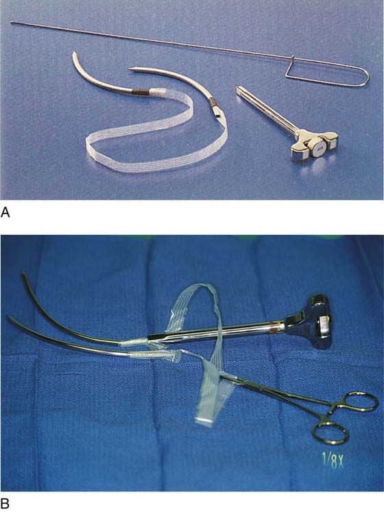
FIGURE 58–1 A. Tension-free vaginal tape (TVT) instrumentation, including (clockwise from top) a Foley catheter guide, a needle introducer/handle, and specially designed needles attached to a synthetic suburethral sling tape. B. Needles have been attached to the handle. A hemostat has been placed on the overlapping plastic sheath.
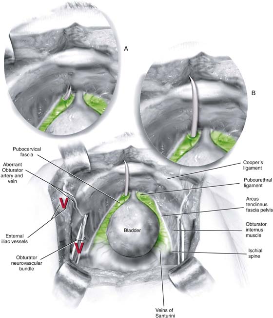
FIGURE 58–2 The retropubic space is visualized. The urethra and the bladder sit on the muscular lining of the vagina (green). A. The needle should penetrate the urogenital diaphragm and enter the retropubic space just medial to the arcus tendineus fascia pelvis and lateral to the urethra. B. It should then maintain direct contact with the back of the pubic bone as it passes toward the anterior abdominal stab wound. Marked with a red “V” are the obturator neurovascular bundle and the external iliac vessels, which should be well away from the tip of the tension-free vaginal tape (TVT) needle.
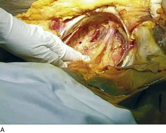
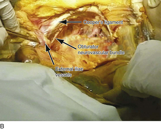
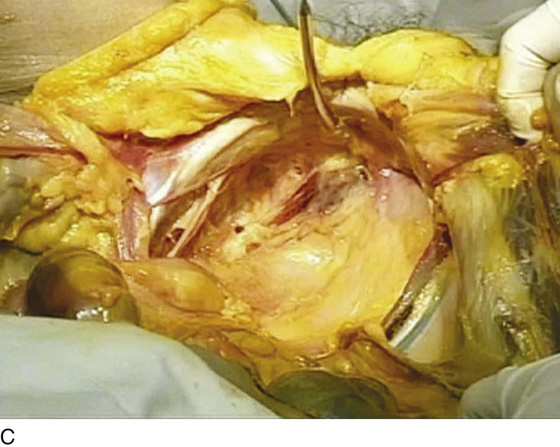
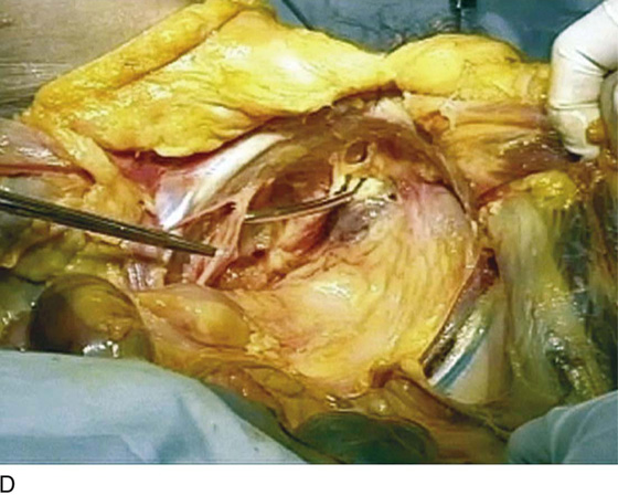
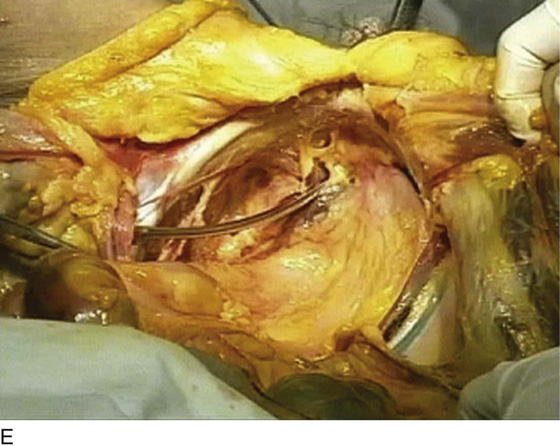
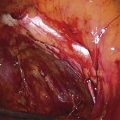
FIGURE 58–3 A. View of the retropubic space of a fresh cadaver. B. Cooper’s ligament, the obturator neurovascular bundle as it exits the pelvis through the obturator foramen, and the external iliac vessels as they exit the pelvis under the inguinal ligament are marked. C. A tension-free vaginal tape (TVT) needle has been passed in an appropriate fashion on the left side of this cadaver. D. The TVT needle is intentionally continued in a cephalad-lateral direction, and one can see how it can easily come into contact with the obturator neurovascular bundle in the retropubic space. E. The TVT needle is intentionally continued in this direction, and one can see how it could potentially come in contact with the external iliac vessels.
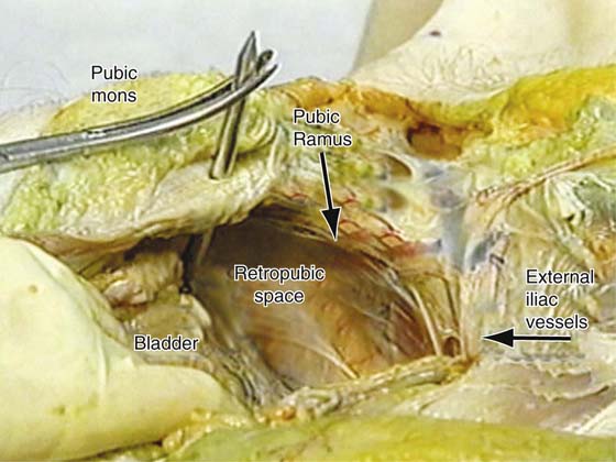
FIGURE 58–4 Retropubic view of an embalmed cadaver. Note the appropriate passage of the tension-free vaginal tape (TVT) needle on the right side and the normal anatomy of other structures in the retropubic space.
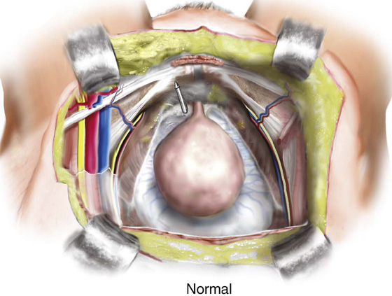
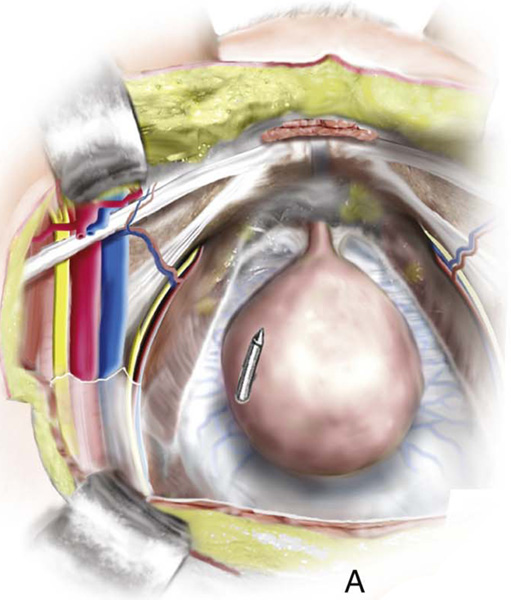
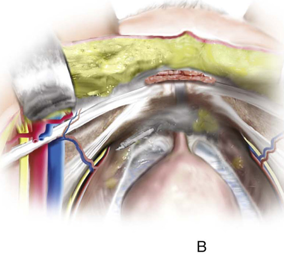
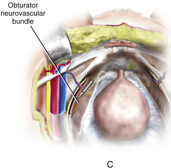
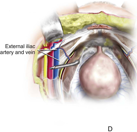
FIGURE 58–5 Retropubic view of appropriate safe passage of a retropubic tension-free vaginal tape (TVT) needle (Normal). A. Cephalad migration of the needle away from the back of the pubic bone is the most common cause of bladder perforation. B. External rotation of the handle will initially result in penetration of the obturator internus muscle by the needle tip, with the potential to injure aberrant vessels along the lateral pelvic sidewall. C. Continued external rotation of the handle with cephalad migration of the needle may result in injury to the obturator neurovascular bundle or (D) the external iliac vessels.
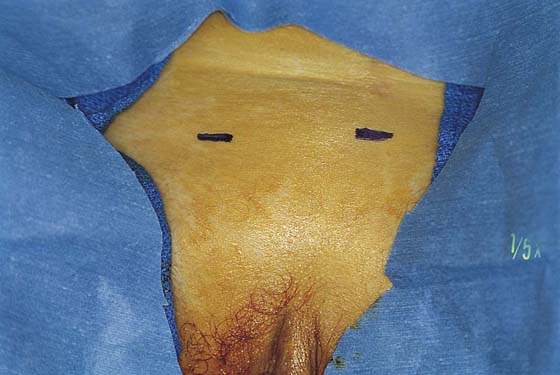
FIGURE 58–6 Site of suprapubic incisions for the tension-free vaginal tape (TVT) procedure.
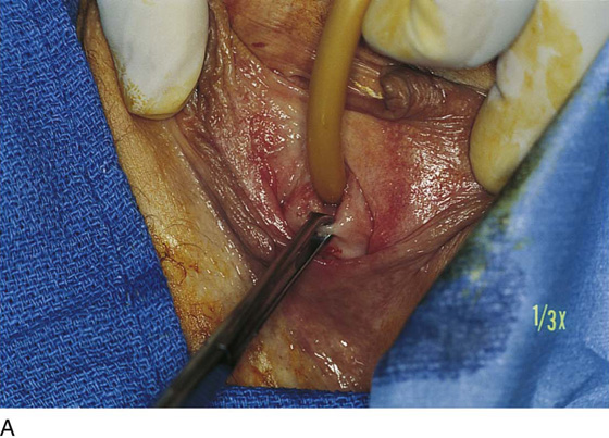
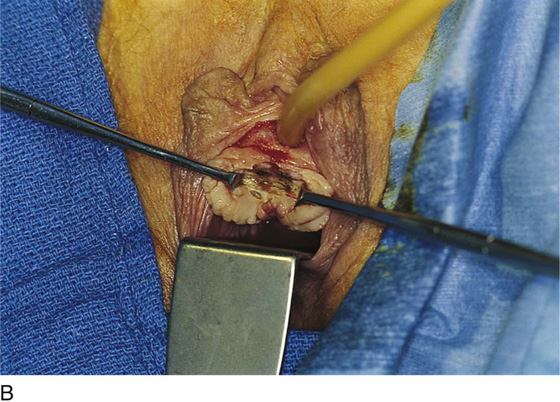
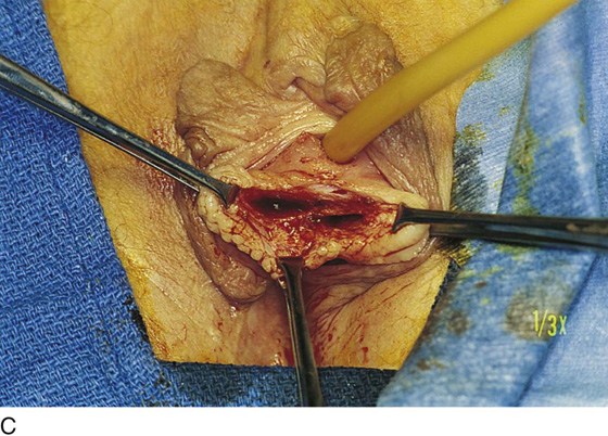
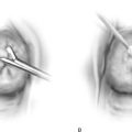
FIGURE 58–7 A. The external urethral meatus is grasped with an Allis clamp at 6 o’clock. B. A small midline incision is made at the level of the midurethra. C. Mayo or Metzenbaum scissors are utilized to create a tunnel to the inferior pubic ramus. The urogenital diaphragm is not penetrated.
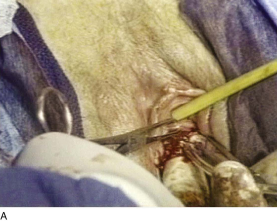
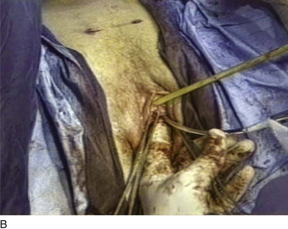
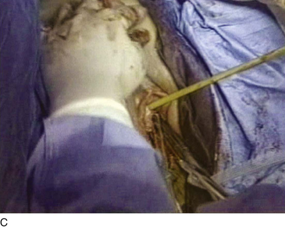
FIGURE 58–8 Proper technique for passing a tension-free vaginal tape (TVT) needle. A. The tip of the needle is placed in the small tunnel that has been created and should come into direct contact with the inferior pubic ramus, pointing toward the ipsilateral shoulder. B. With the index finger of the nondominant hand in the vagina and the thumb on the shaft of the needle, the tip is pushed through the urogenital diaphragm. C. Once the resistance of the urogenital diaphragm is overcome, the handle is dropped and the needle is moved in a medial and superior direction, while direct contact with the back of the pubic bone is maintained. Cephalad migration must be avoided. The tip of the needle is then palpated suprapubically and is guided to exit through the previously created stab incision.
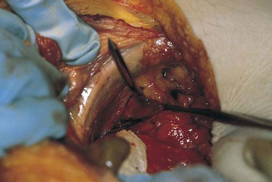
FIGURE 58–9 The direction of the needle along the back of the pubic bone is demonstrated in a cadaver.
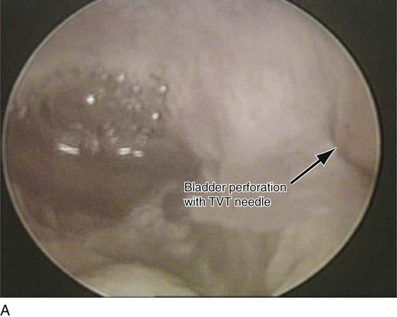
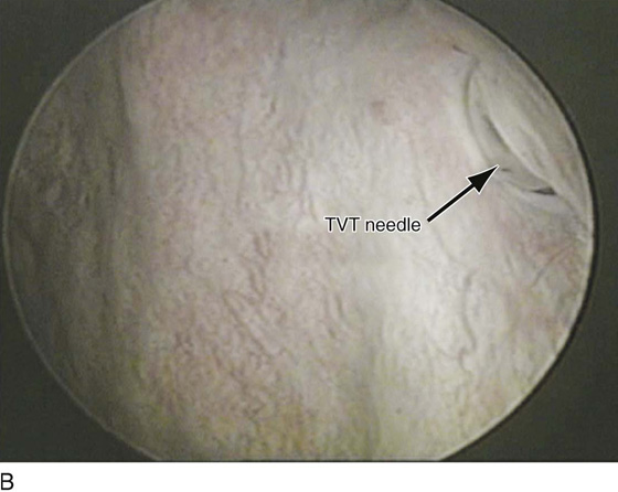
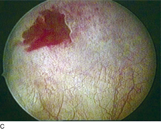
FIGURE 58–10 A. Bladder perforation with a tension-free vaginal tape (TVT) on the patient’s left side. B. The shaft of the needle is now visible as it is withdrawn back into the vagina. C. The defect that is left in the bladder.
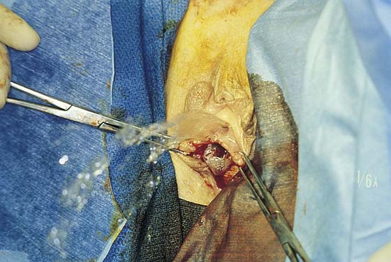
FIGURE 58–11 The tape has been passed suprapubically on both sides. Leakage of urine during a coughing stress test indicates the need for adjustment of the sling material.
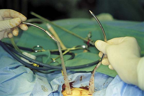
FIGURE 58–12 Tension-free vaginal tape (TVT) needles and a plastic sheath containing Prolene tape have been passed up through suprapubic stab wounds.
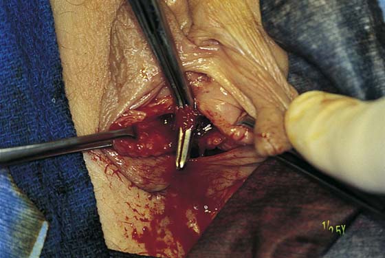
FIGURE 58–13 A right-angle clamp stabilizes the Prolene while the plastic sheath is being withdrawn suprapubically.
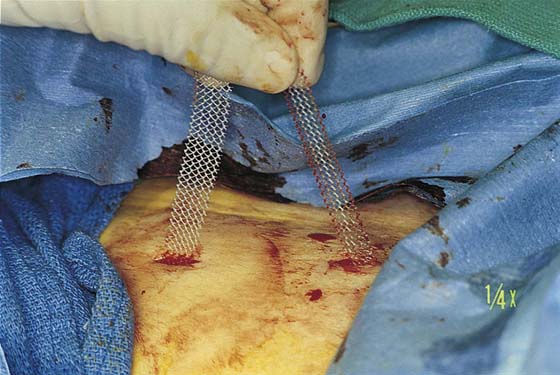
FIGURE 58–14 Prolene tape after the plastic sheath has been removed.
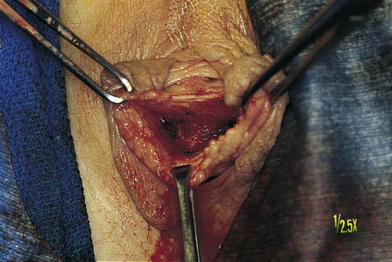
FIGURE 58–15 Tension-free Prolene tape at the level of the midurethra.
More recently, a suprapubic approach to synthetic retropubic midurethral slings has been described. The needle is passed from the suprapubic stab wound along the back of the symphysis to exit into the vaginal incision. The needle should maintain direct contact with the posterior aspect of the pubic bone as it passes through the retropubic space. To ensure that the needle exits in the midurethra, not at the level of the bladder neck, it should be laid down flat on the abdomen as it transcends through the retropubic space (Figs. 58–16 and 58–17).
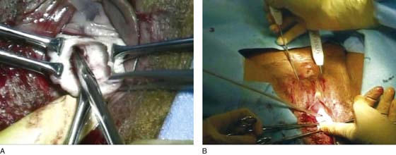
FIGURE 58–16 A. Dissection for an abdominal guide procedure (Gynecare, Somerville, NJ). Note: The vaginal incision is larger to allow the tip of the finger to palpate the inferior pubic ramus and pick up the needle as it passes through the urogenital diaphragm. B. Needles being passed suprapubically into the vagina.
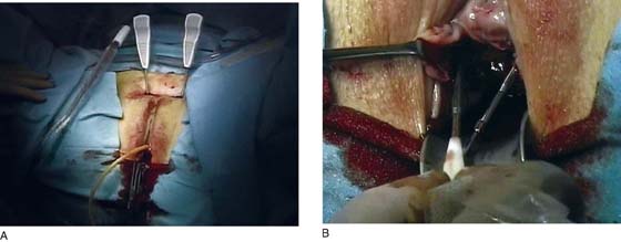
FIGURE 58–17 A. The SPARC procedure (American Medical Systems, Minneapolis, Minn), which is a suprapubic approach to a retropubic synthetic midurethral sling. B. The connector utilized with the SPARC procedure allows transfer of the sling into the suprapubic area.
Transobturator Synthetic Midurethral Slings
DeLorme described the first transobturator synthetic midurethral sling. The theoretical advantages of a transobturator sling include less bladder injury, because the device largely avoids the space of Retzius, and reduced potential for vascular and bowel injury. These slings are passed through a group of inner thigh muscles, specifically, the gracilis tendon, the adductor brevis, and the obturator externus. Figure 58–18 illustrates the origins and insertions of these muscles, as well as other medial thigh muscles. Currently, two techniques are available for placing a transobturator sling. Both techniques involve specially designed needles that are passed from the obturator region into the vagina or from the vagina into the obturator region. Figures 58–19 through 58–26 demonstrate the anatomy of the region via extensive cadaveric dissection. When passed from outside-in, the sling is directed from a small incision lateral to the clitoris at the inferior edge of the adductor longus tendon, through the obturator foramen, around the ischiopubic ramus, and into the anterior vagina at the level of the midurethra. It passes in order through the following structures: gracilis, adductor brevis muscle, obturator externus muscle, obturator membrane, and beneath or through the obturator internus muscle and periurethral endopelvic connective tissue; it finally exits into the opened vagina. In the technique utilized for the inside-out approach, the same structures are passed through in the opposite direction. Figures 58–27 and 58–28 demonstrate the technique for placement of a transobturator sling via an outside-in approach and an inside-out approach.
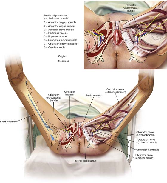
FIGURE 58–18 Illustration of the anatomy of the inner thigh. Note the origins and insertion of medial thigh muscles.
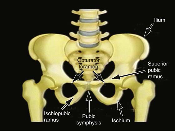
FIGURE 58–19 The bony pelvis. Note the superior pubic ramus and the obturator foramen.
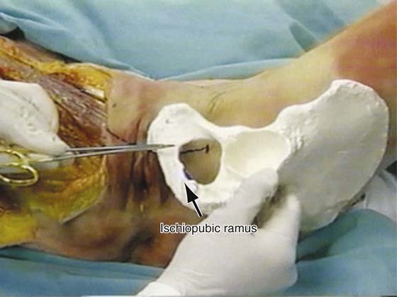
FIGURE 58–20 The bony pelvis held in front of a cadaver to demonstrate the anatomic location of the ischiopubic ramus and the obturator foramen.
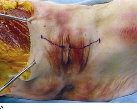
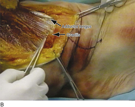
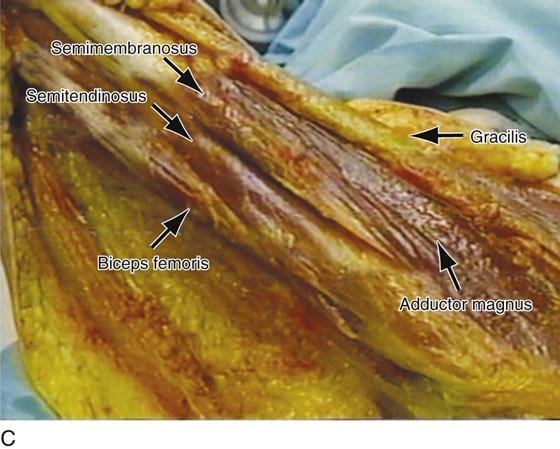
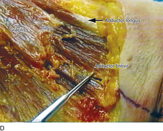
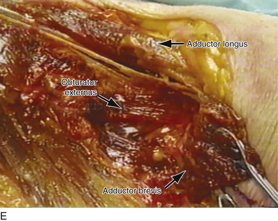
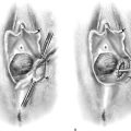
FIGURE 58–21 A. The anatomic location of a transobturator suburethral sling is drawn on the cadaver. B. The obturator region on the cadaver’s left side is open to demonstrate the anatomic site of the gracilis and adductor longus muscles. C. Muscles of the inner thigh. D. The gracilis muscle has been cut to expose the adductor brevis muscle. E. The adductor brevis muscle is displaced to demonstrate the location of the obturator externus muscle, the site of which lies directly on the obturator membrane.
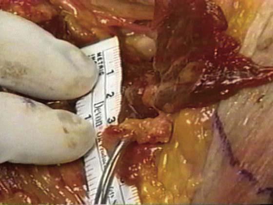
FIGURE 58–22 Distance from the entrance point of the transobturator needle to the obturator neurovascular bundle as it exits the obturator canal.
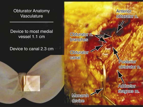
FIGURE 58–23 Anatomy of the obturator region. Average distance from the Monarch device to the obturator vessels in six fresh-frozen cadavers.
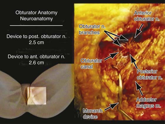
FIGURE 58–24 Anatomy of the obturator region. Average distance from Monarch device to obturator nerves in six fresh-frozen cadavers.
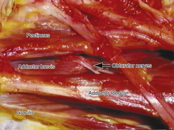
FIGURE 58–25 Relationship of the obturator nerves to the muscles of the obturator region.
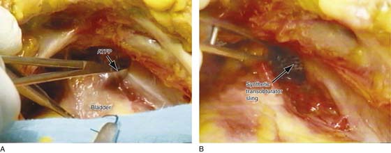
FIGURE 58–26 A. View of the retropubic space of a cadaver. The clamp is pointing to the arcus tendineus fascia pelvis and the obturator internus muscle. B. This area has been opened up to demonstrate the normal anatomic location of a transobturator sling. Note: The sling should not enter the retropubic space. It should remain deep to the arcus tendineus fascia pelvis and the obturator internus muscle.
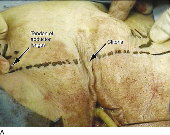
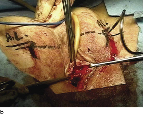
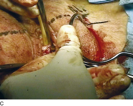
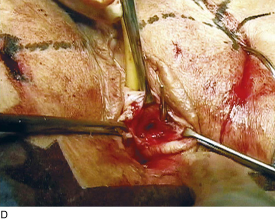
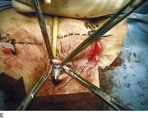
FIGURE 58–27 A. Anatomic location of the clitoris and tendon of the adductor longus. These are important landmarks when a transobturator sling procedure is performed. B. Monarch needle being passed into the obturator region. C. Appropriate positioning of the nondependent hand on the curvature of the needle so that downward pressure can be applied to facilitate penetration of the needle through the obturator membrane. D. The needle has been passed through the obturator membrane around the ischiopubic ramus and is shown exiting into the lateral part of the vaginal incision. E. The sling has been placed, and a right-angle clamp is used to stabilize the sling while the plastic sheath is removed.
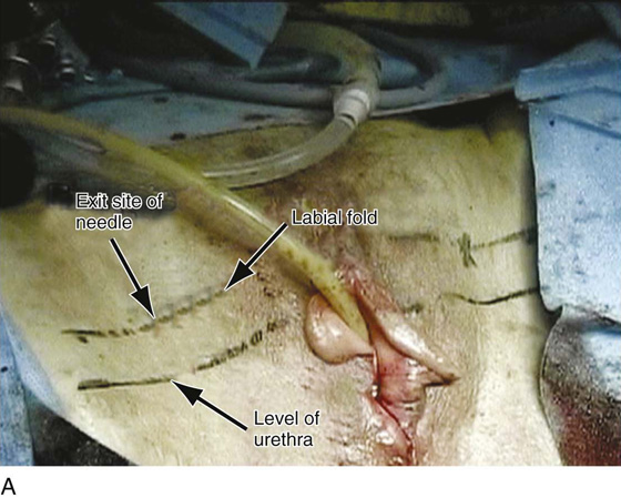
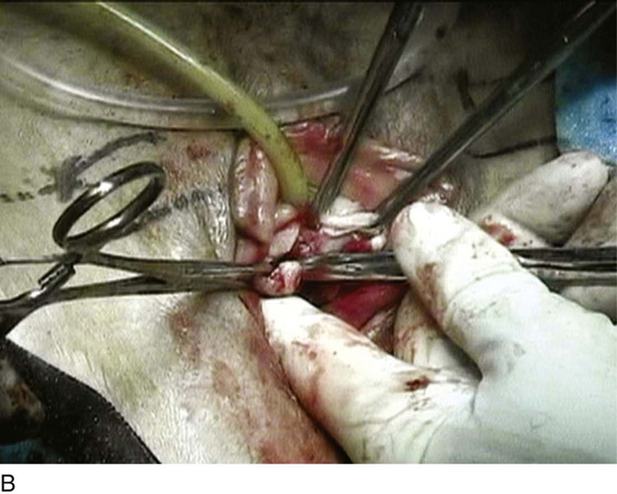
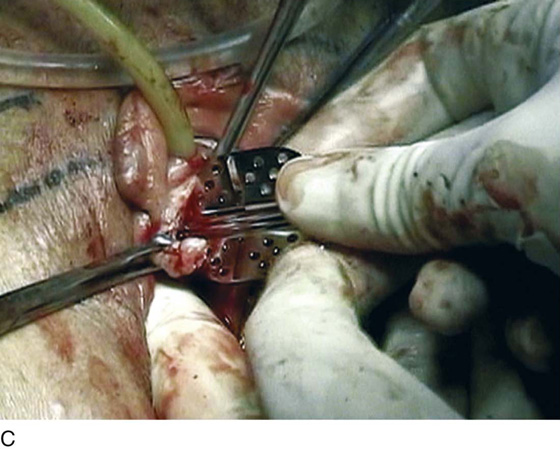
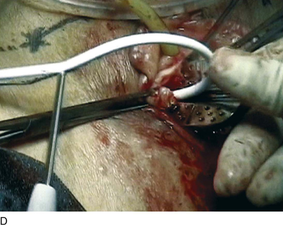
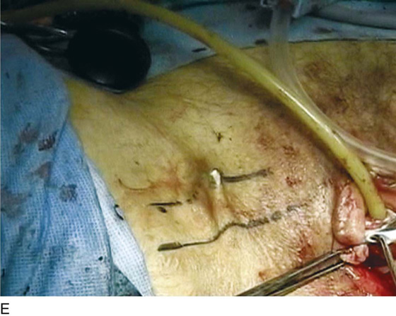
FIGURE 58–28 Technique for the tension-free vaginal tape (TVT)-O procedure (GyneCare, Somerville, NJ). This procedure utilizes specially designed needles that are passed from a vaginal incision into the obturator region. A. The exit site of the needle is marked. It should be 2 cm above the level of the urethra and 2 cm lateral to the labial fold. B. After a midline anterior vaginal wall incision is made, Metzenbaum scissors directed at a 45° angle are used to tunnel under the inferior pubic ramus toward the obturator region. The tips of the scissors should penetrate the obturator membrane. When this occurs, distinct resistance is overcome. C. A guide is then placed in the tunnel that is created by the scissors. D. A specially designed needle is passed, with the help of the guide, through the obturator membrane. E. The guide is then removed and the needle is passed into the obturator region, exiting at the previously marked exit site.
Synthetic Single-Incision Midurethral Slings
Single-incision midurethral slings are approximately 10 cm in length, if one assumes that they are symmetrically and appropriately placed at the midline; the various anatomic structures that the sling can penetrate include the periurethral attachment to the pubic bone, or what is sometimes termed the urogenital diaphragm or obturator internus muscle. When a single-incision sling is performed, the anatomic objective is for the sling to be placed in durable tissue. If the sling is placed in a more lateral direction, it would penetrate directly into the obturator internus muscle with the possibility of duplicating a transobturator-type sling. The length of the sling does not allow the sling to pass through the obturator membrane; thus the inner thigh muscles, nerves, and blood vessels could not be damaged. If the sling is placed in a more medial fashion, stimulating the original retropubic synthetic sling, it will penetrate the urogenital diaphragm or the paraurethral attachment to the inferior pubic ramus and enter the lowest portion of the retropubic space. Structures at risk include the urethra, the bladder, and the aberrant retropubic blood vessels that drape down the lateral pelvic sidewall, as well as the large veins of the anterior vaginal wall. Of note, the sling, if placed appropriately, is not long enough to reach the obturator neurovascular bundle as it exits the pelvis through the obturator canal. Figure 58–29 illustrates a variety of potential placements of a single-incision sling based on the technique and device that are utilized.
At the present time, indications for these procedures are very controversial because of the lack of a standard technique for placement and minimal outcome data. The perceived advantages of the mini-slings are that they are less invasive, quicker to place, and safer.
The procedure can be performed with the patient under general, regional, or local anesthesia. The bladder is drained with a catheter, and a 2- to 3-cm incision is made in the mid to distal portion of the anterior vaginal wall (Fig. 58–30). Hydrodistention facilitates dissection of the anterior vaginal wall epithelium off the urethra. This may minimize bleeding during dissection. The dissection is taken laterally to the inferior pubic ramus, with assurance that the lateral portion of the urethra is dissected away from the anterior vaginal wall (Figs. 58–31 and 58–32). The sling is then inserted with an inserter or a sling carrier device. The other end of the sling is inserted in a similar manner. Appropriate tensioning of these slings remains the most challenging aspect of the procedure. In our experience, these slings need to be tensioned much more tightly than retropubic or transobturator synthetic slings (Fig. 58–33). The single-incision sling should be left in direct contact with the posterior urethra. This is in direct contradiction to what has been taught with previous synthetic slings, which should be placed very loosely. Once the appropriate position of the sling is reached, the surgeon must go to great lengths to avoid inadvertently loosening the sling while removing the needle attachment. Patients under monitored anesthesia care (MAC) or local anesthesia can undergo a cough test to aid in tensioning. Once the mesh is in place, cystourethroscopy is performed to ensure that no inadvertent injury to the urethra or bladder occurs.
Currently available synthetic midurethral slings include the TVT Secur System (Ethicon Women’s Health & Urology, Sommerville, NJ), which was the first commercially available sling; it utilizes an 8 × 1.1-cm laser-cut Prolene mesh. At the ends of the Prolene mesh are absorbable fixation tips made of Vicryl and polydioxanone (PDS) suture material. The sling is attached to a steel inserter with a spade needle tip (Fig. 58–34). The mesh can be placed in a “hammock” or U shape. The urethra is deflected in the opposite direction with the use of a catheter guide in the Foley catheter when the U-shaped sling is placed. The inserter is used to deliver the mesh and allow adjustment until the wire is released. Figures 58–35 through 58–39 demonstrate appropriate techniques for placement of a TVT Secur device. The second single-incision sling that came to market was the MiniArc (American Medical Systems, Minnetonka, Minn) sling. This 2.3-mm-diameter blunt needle requires a lesser insertion force as compared with the TVT Secur (4.5 lb vs. 2.5 lb). The sling is an 8.5 × 1.1-cm polypropylene mesh with a midline mark. The MiniArc uses a blunt-tip needle to deliver the sling’s self-fixating tip. The needle has a redocking feature that provides the ability to reconnect to the mesh and allow for additional tensioning. Compared with the TVT Secur, the MiniArc sling has a smaller needle diameter (8.1 mm vs. 2.3 mm) (Figs. 58–40 and 58–41). Another slim needle design sling is the Solyx SIS System (Boston Scientific, Natick, Mass). This sling features a different delivery and tensioning system. The sling is a polypropylene mesh that measures 9 cm in length. The mesh itself snap-fits to the delivery device, which prevents premature release of the mesh off the device. The delivery device has a deployment mechanism that allows appropriate tensioning without premature release of the mesh. The mesh has “De-Tanged” edges in the middle portion of the sling measuring 4 cm. After appropriate tensioning, the mesh is set in place by grasping the deployment mechanism and pulling the delivery device handle back (Figs. 58–42 and 58–43). Both MiniArc and Solyx single-incision slings are intended to be passed directly into the obturator internus muscle.
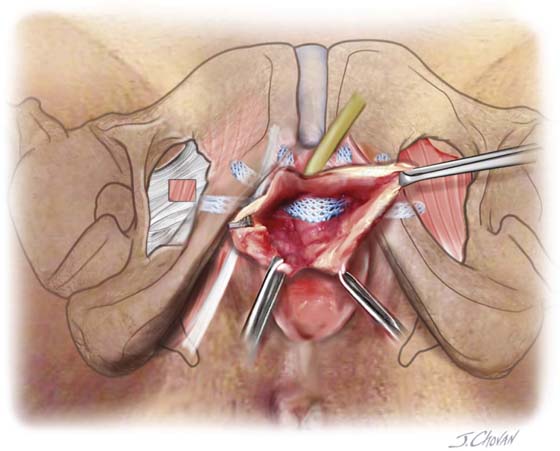
FIGURE 58–29 Illustration demonstrating a variety of potential placements of a single-incision sling based on the technique and the device that are utilized.
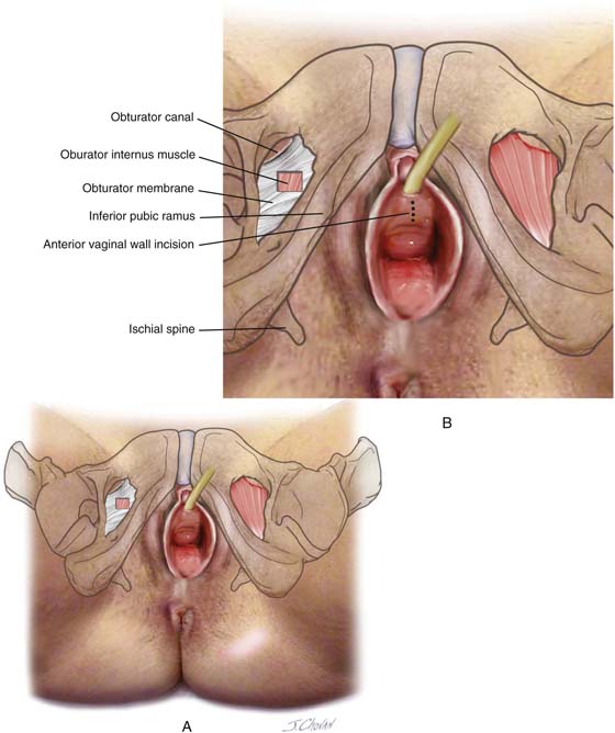
FIGURE 58–30 A. View of the anterior vaginal wall as it relates to the obturator membrane and the obturator internus muscle. B. Level of anterior vaginal wall incision is marked.
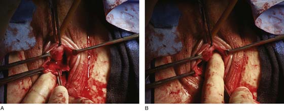
FIGURE 58–31 A. Anterior vaginal wall incision for a single-incision sling should completely mobilize the distal anterior vaginal wall off the posterior urethra. B. The incision should be large enough for placement of the surgeon’s index finger.
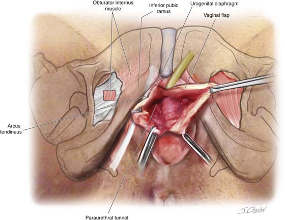
FIGURE 58–32 Illustration of appropriate anterior vaginal incision made for a single-incision sling. Note that dissection extends paraurethrally to the inferior pubic ramus.
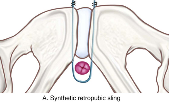
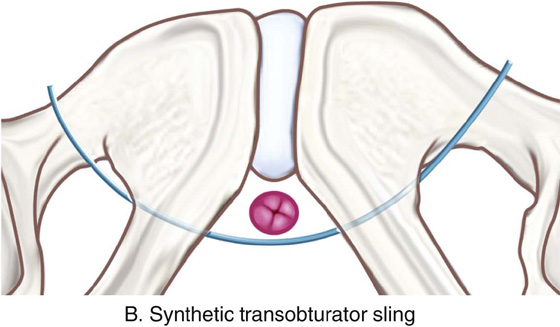
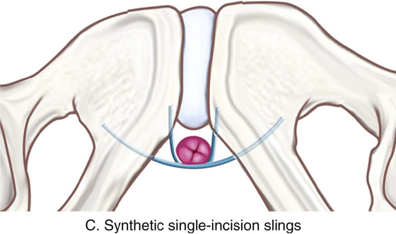
FIGURE 58–33 Tensioning of synthetic midurethral slings. A. Synthetic retropubic slings are usually left very loose, easily allowing an instrument to be passed between the sling and the posterior urethra. B. Transobturator synthetic midurethral slings are usually tensioned slightly tighter than retropubic slings. C. Single-incision slings are tensioned so that they come in direct contact with the posterior urethra, making it very difficult to pass an instrument between the sling and the posterior urethra.
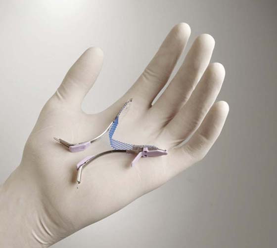
FIGURE 58–34 The tension-free vaginal tape (TVT) Secur sling (Ethicon Women’s Health & Urology).
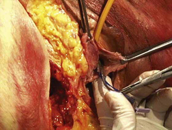
FIGURE 58–35 Techniques utilized for passage of a tension-free vaginal tape (TVT) Secur device. Note that the vaginal incision should be large enough to allow the tip of the needle to come in direct contact with the inferior pubic ramus. The index finger of the nondominant hand is placed in the anterior vaginal fornix, and the thumb of the nondominant hand is used to advance the tip into the tissue. A needle holder is used as the handle for the device.
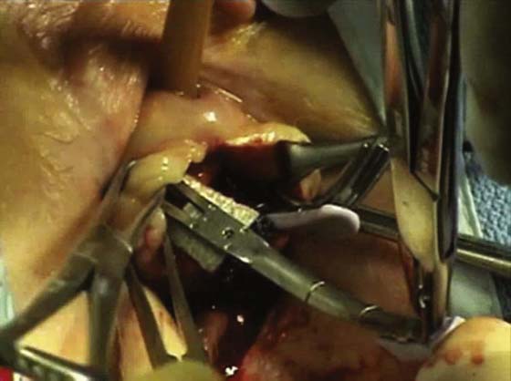
FIGURE 58–36 Patient undergoing tension-free vaginal tape (TVT) Secur procedure with U-shaped placement. Note that the needle tip should penetrate the urogenital diaphragm just lateral to the urethra. A catheter guide should always be utilized when a U placement procedure is performed.
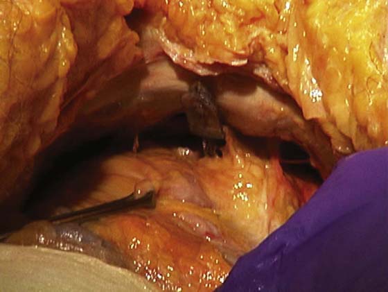
FIGURE 58–37 Retropubic view of a cadaver in which a tension-free vaginal tape (TVT) Secur needle has been passed via the U-shape technique. Note that the needle tip should be in direct contact with the back of the pubic bone.
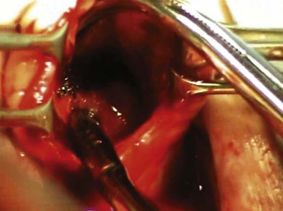
FIGURE 58–38 U-placed tension-free vaginal tape (TVT) Secur sling after removal of the inserter. Note that the sling should be tensioned so that it is in direct contact with the posterior urethra.
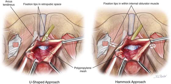
FIGURE 58–39 Placement of tension-free vaginal tape (TVT) Secur single-incision sling, illustrating U-shaped placement where the needle penetrates the urogenital diaphragm, and hammock placement where the needle is passed directly into the obturator internus muscle.
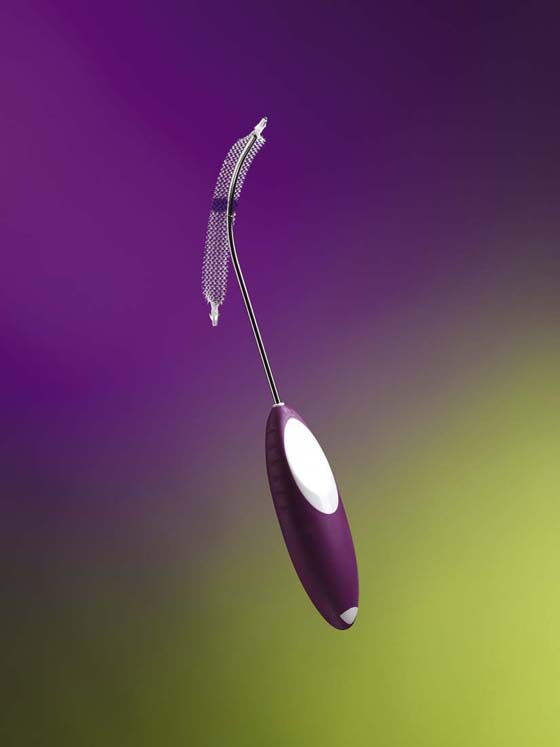
FIGURE 58–40 The MiniArc sling. (Courtesy American Medical Systems, Inc., Minnetonka, Minnesota. www.AmericanMedicalSystems.com)
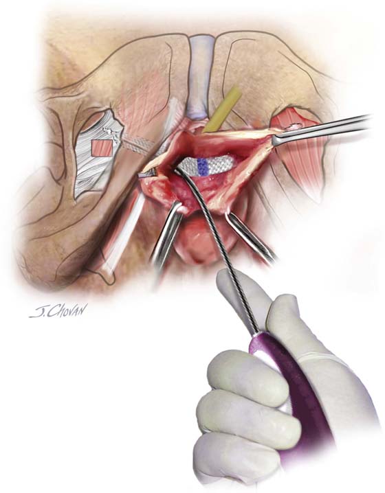
FIGURE 58–41 Technique for placement of the MiniArc single-incision sling (American Medical Systems). Note that the sling is placed directly into the obturator internus muscle.
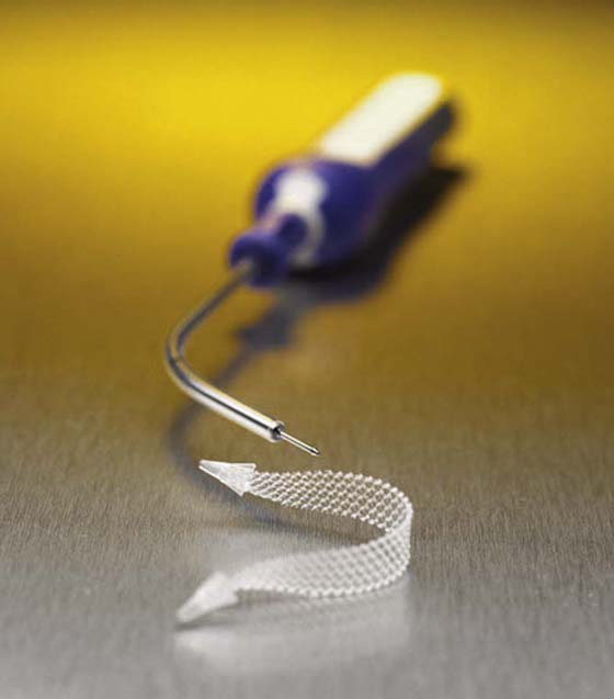
FIGURE 58–42 The Solyx sling (Boston Scientific, Natick, MA). (Photos courtesy Boston Scientific Corporation.)
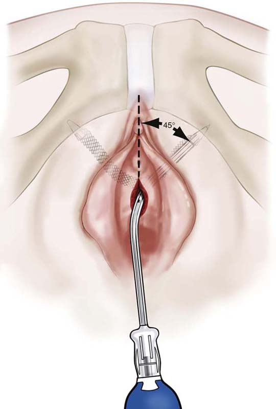
FIGURE 58–43 Illustration demonstrating placement of the Solyx sling (Boston Scientific, Natick, MA). (Photos courtesy Boston Scientific Corporation.)
Techniques Used to Cut or Remove Sling Material
A certain percentage of women undergoing a suburethral sling procedure will require the sling to be cut or removed secondary to urethral obstruction or voiding dysfunction, at times because of erosion or excursion of the sling into the vagina, urethra, or bladder, or rarely, because of severe infection or allergic reaction. Urethral obstruction or voiding dysfunction can occur with any anti-incontinence procedure and usually results from a sling being tied or placed too tightly. It also may relate to the fact that the sling material is irritating and may cause symptoms of urgency and frequency, which can occur de novo anywhere from 5% to 20% of the time after sling procedures are performed. When this occurs, the sling must be adjusted, cut, or taken down. The technique used to perform this procedure depends on the sling material and how it interacts with the patient’s tissue. For example, certain autologous or allograft slings may aggressively incorporate with the surrounding tissue, making it impossible to differentiate the sling material from the patient’s tissue. In contrast, certain other materials, whether synthetic or biologic, may be easily identifiable and easily dissected away from the patient’s tissue. Whether the patient redevelops stress incontinence or maintains her continence is based on the degree of scarification, how aggressive the takedown is, and what sling material was utilized. Figure 58–44 demonstrates the technique of isolating and cutting a cadaveric fascial sling with subsequent interposition of another piece of cadaveric fascia. Figure 58–45 demonstrates the technique of cutting a synthetic midurethral sling. Very rarely, synthetic midurethral slings may be placed inappropriately in the wall of the urethra or may erode into the urethra. Figure 58–46 demonstrates the technique of isolating, mobilizing, and cutting the suburethral portion of the sling and then fixing the defect within the urethra. The urethral defect should be repaired as one would repair a urethrovaginal fistula. Figures 58–47 through 58–50 provide examples of vaginal excursions and permanent sling material in the bladder.
At times patients who have undergone bladder neck suspension or a suburethral sling procedure for stress incontinence may develop severe voiding dysfunction or even retention, requiring a vaginal urethrolysis.
The technique of vaginal urethrolysis (Fig. 58–51) involves placement of a transurethral Foley catheter with a 30-mL balloon within the bladder. Initial traction on the catheter with simultaneous vaginal palpation of the bladder neck subjectively assesses the degree and extent of scarring, elevation, and fixation of the urethrovesical junction. The goal of a vaginal urethrolysis is to create some mobility at the proximal urethra and bladder neck. This may at times require removal or loosening of the sling material.
An inverted-U incision (see Fig. 58–51A) or a midline anterior vaginal wall incision is made. Urethral mobility is created by dissecting toward the inferior pubic ramus on each side (see Fig. 58–51B). This may involve perforating the urogenital diaphragm. Urethral mobility is subjectively assessed via traction on the Foley catheter. Some also advocate the placement of a labial fat pad around the urethra to prevent rescarification. The author would discourage any attempts at resuspension.
Figure 58–52 reviews a technique of removal of a synthetic sling that had created significant voiding dysfunction.
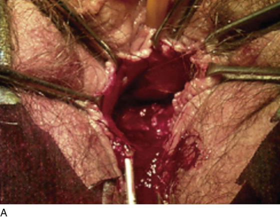
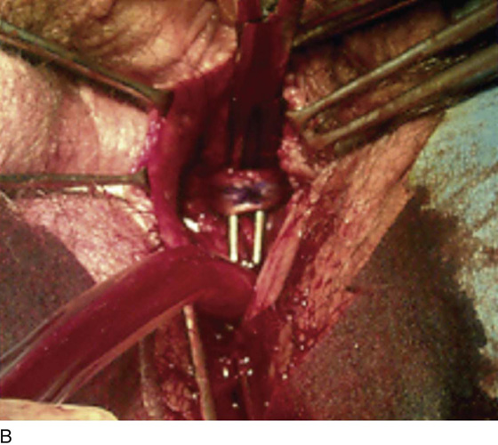
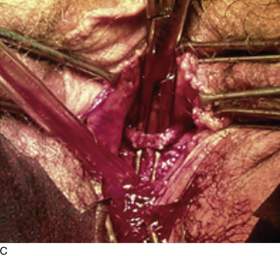
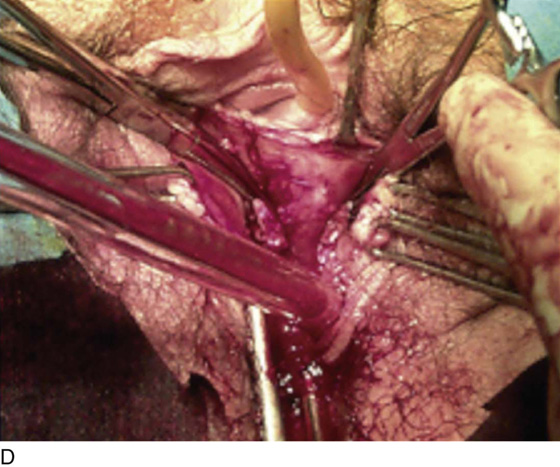
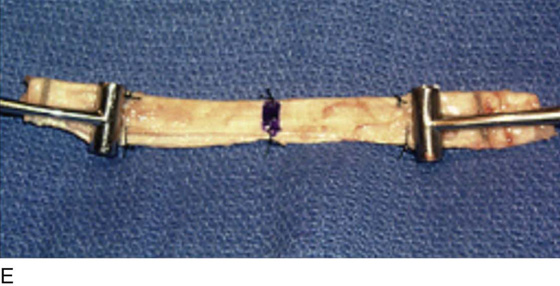
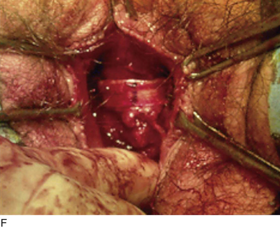
FIGURE 58–44 A. Cadaveric fascia lata sling causing urethral obstruction. B. Right-angle clamp has been passed between the sling and the urethra. C. Sling is being cut. D. Sling has been cut, and retracted ends are held in clamps. E. Cadaveric fascia to be interposed between the two cut ends. F. Piece of cadaveric fascia has been interposed. Note appropriate placement of tension of the sling.
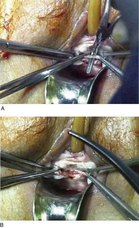
FIGURE 58–45 A. Technique for takedown of a synthetic midurethral sling. Note that the sling is identified, and a right-angle clamp is passed between the sling and the urethra. The edges of the sling are grasped with clamps, and the sling is cut at the midline. Of note, it is important to completely dissect the sling away from the urethra to ensure that the voiding dysfunction will be resolved. B. The sling has been cut, and the edges of the sling remain on the vaginal side of the urogenital diaphragm.
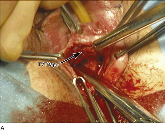
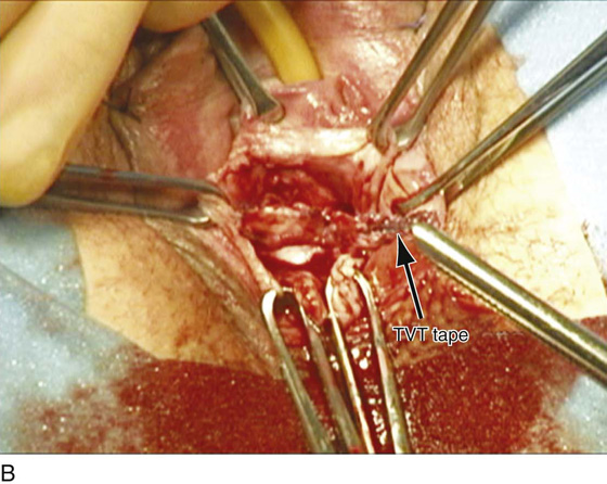
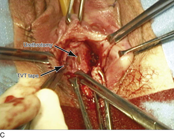
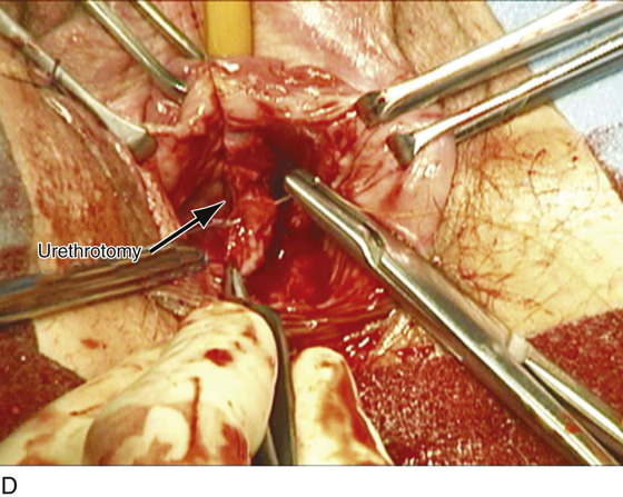
FIGURE 58–46 Synthetic midurethral sling eroded or placed in the wall of the urethra. A. Tape present in the wall of the urethra. B. Tape has been dissected away from the urethral wall. C. Resultant urethral defect is seen. D. Repair of the urethral defect should be done with interrupted 4-0 delayed absorbable sutures.
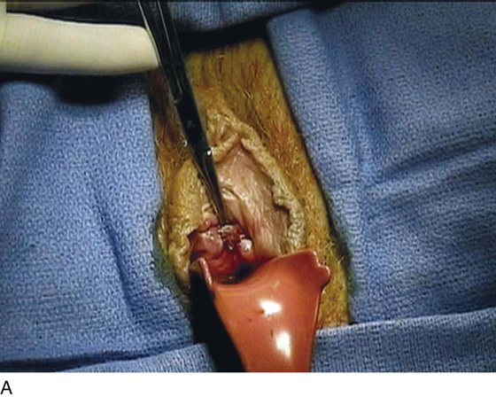
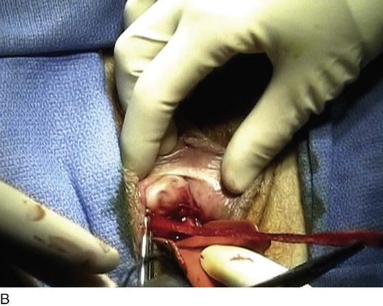
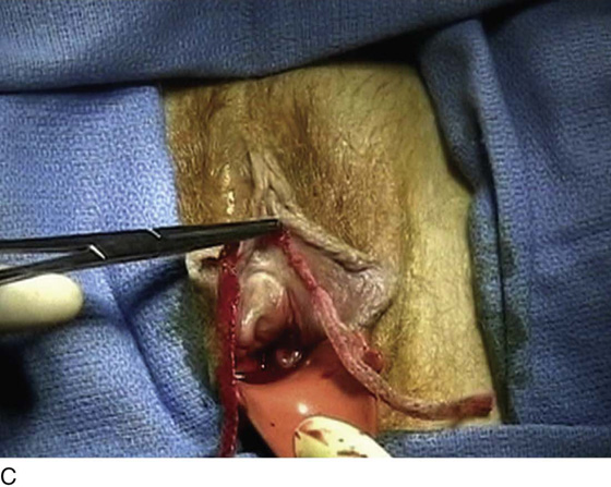
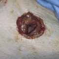
FIGURE 58–47 A. Excursion of an OB-Tape procedure (Mentor, Santa Barbara, CA). B. The tape is removed from one side. C. The entire tape is removed intact 4 weeks after the procedure.
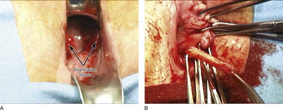
FIGURE 58–48 A. Large areas of granulation tissue secondary to excursion or erosion of an OB-Tape (Mentor, Santa Barbara, CA). B. The OB-Tape is removed intact 6 months after it was placed.
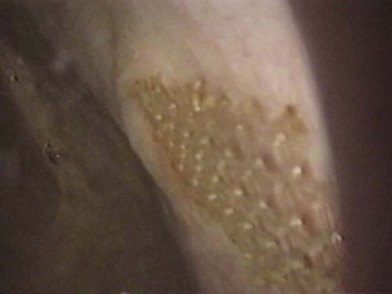
FIGURE 58–49 Synthetic sling material in the bladder 3 months after a synthetic midurethral sling procedure.
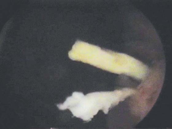
FIGURE 58–50 Permanent suture in the bladder a year after a bone anchor sling.
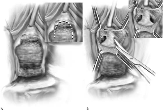
FIGURE 58–51 Technique of vaginal urethrolysis. A. An inverted-U incision is made on the vagina. B. Sharp dissection lateral to the bladder neck with sharp penetration of the urogenital diaphragm allows entry into the retropubic space with the possibility of creating some urethral mobility.
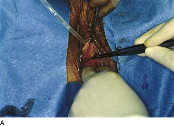
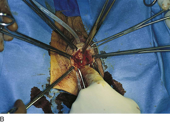
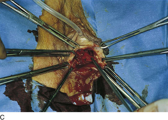

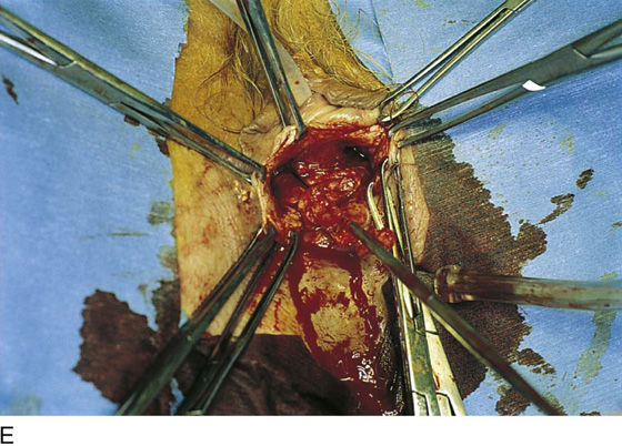
FIGURE 58–52 Technique of vaginal removal of a bone-anchored Protogen suburethral sling. A. Anatomic location of the level of the sling. B. Identification of the Protogen sling (Boston Scientific, Natick, MA). C. Dissection of sling material off the urethra. D. Retrieval of sutures that had been anchored in bone on the left side. E. Removal of sling material and suture from the right side. Note that after complete removal of the sling material, the obstruction at the level of the proximal urethra has been relieved.