Chapter 15 Spinal Cord Stimulation
Spinal cord stimulation (SCS) has been used for a wide variety of conditions (see later discussion of indications). The procedure is effective in patients who have chronic intractable pain of the trunk or limbs. Neuropathic pain responds well to SCS, whereas the procedure is usually ineffective in treating nociceptive pain and central pain. SCS has been used with increasing effectiveness because of improvements in patient selection criteria, lead placement accuracy, and devices (multipolar and multichannel). Studies have now shown that SCS is cost effective in comparison with conventional medical management, especially in the treatment of failed back surgery syndrome [1]. Kumar and associates [1], who conducted a 22-year study, reported effective long-term pain control, with a mean follow-up of 97.6 months, in 59.3% of all patients screened and 74.1% of the 328 patients in whom the hardware systems were internalized.
Treatment objectives


Indications
General considerations in the selection of SCS for a particular patient are as follows:


Special indications for this procedure include the following:


Contraindications
Absolute contraindications to SCS are as follows:


The following conditions are relative contraindications to SCS:


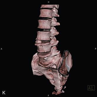
Radiologic anatomy
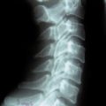
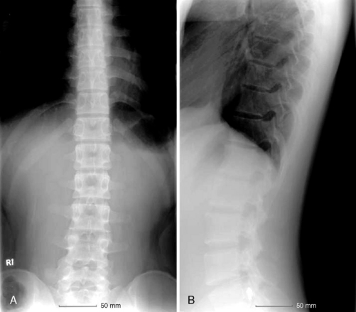
Figure 15-1 shows examples of the radiographic films that should be obtained in order to evaluate the following aspects of the thoracolumbar spine:


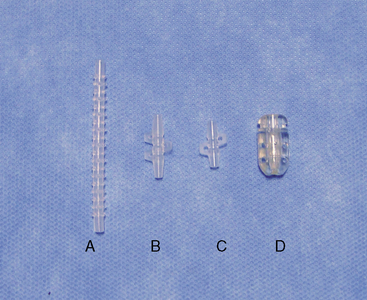
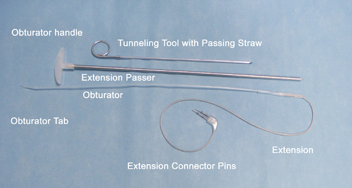
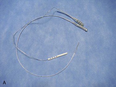
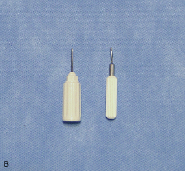
Instrumentation
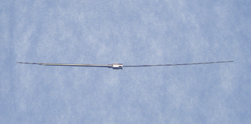
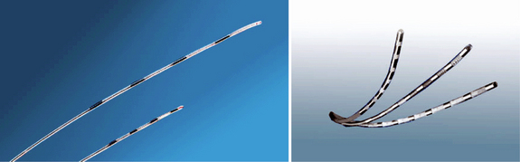
The following instruments and equipment are needed for a trial of SCS :


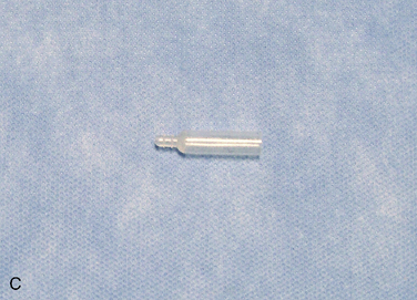
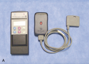
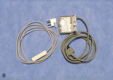
The equipments for implantation of pulse generator are as follows:


Procedure
Implantation of the Trial Lead
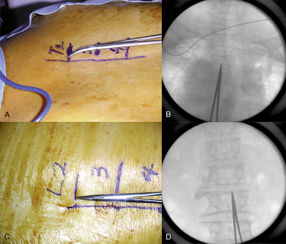
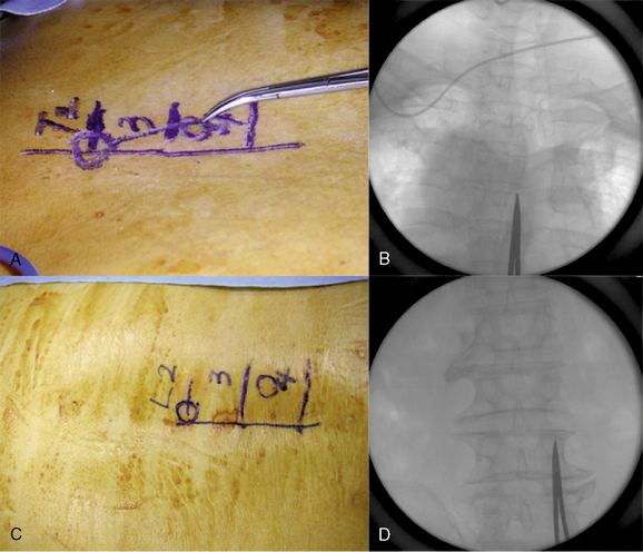
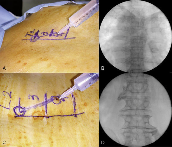
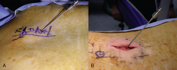
Preparation for Implantation of the Trial Lead
Table 15.1 Pain Location, Lead Tip Level, and Entry Level for Spinal Cord Stimulation
| Pain Location | Lead Tip Level | Entry level |
|---|---|---|
| Foot only | T11-L1 (L1) | L2-L3 |
| Anterior thigh | T11-T12 | L2-L3 |
| Posterior thigh | T11-L1 | L2-L3 |
| Perineum | T11-L1 (midline) | L2-L3 |
| Buttock and lower extremity | T9-T10 (T11-L1) | T12-L1 |
| Lower back | T9-T10 (midline) | T12-L1 |
| Upper chest wall | T1-T2 | T4-T6 |
| Upper extremity | C3-C5 | T1-T3 |
| Hand | C5-C6 | T1-T3 |
| Shoulder | C2-C4 | T1-T3 |
| Neck | C1-C2 | T1-T3 |
| Jaw | C2 | T1-T3 |
Data from Medtronic, Inc: Spinal Cord Stimulation—Percutaneous Lead Implantation Guide. (NI-2772EN, UC9604345aEN) Minneapolis, MN, Medtronic Inc, 1999, p 11; and Barolat G, Massaro F, He J, et al. Mapping of the sensory responses to epidural stimulation of the intraspinal neural structures in man. J Neurosurg 1993;78:233-239.
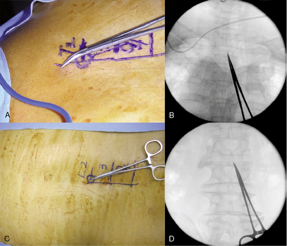
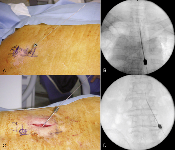
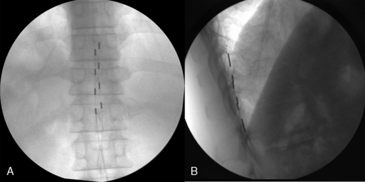
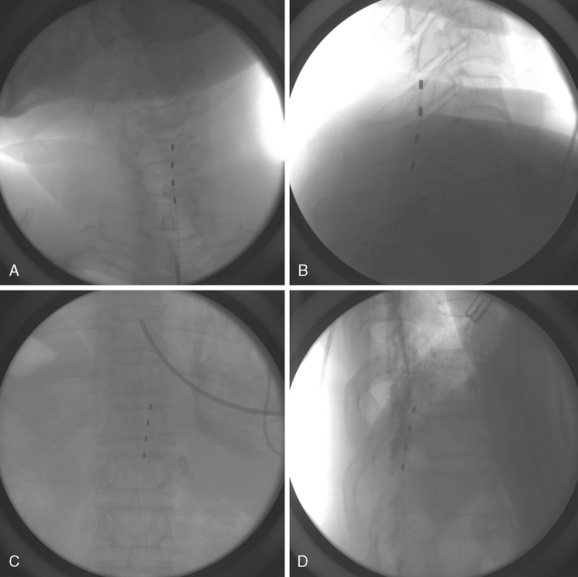
Initial Lead Placement
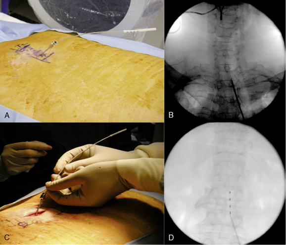
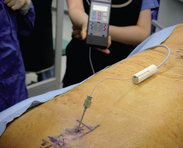
Intraoperative Test Stimulation (Fig. 15-18)
Completion of Trial Procedure
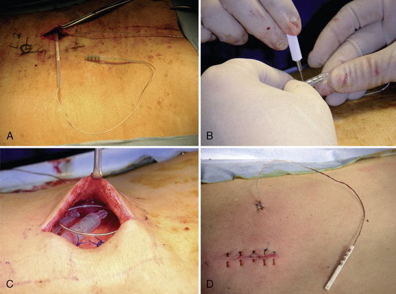
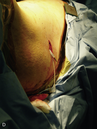
Implantation of the Pulse Generator
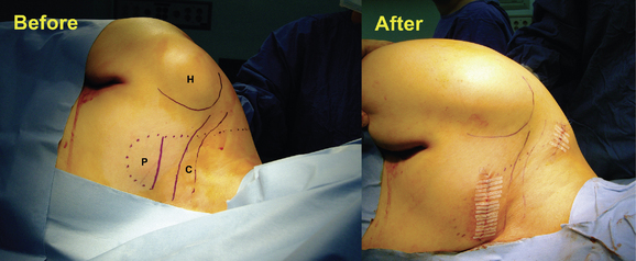
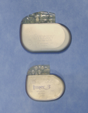
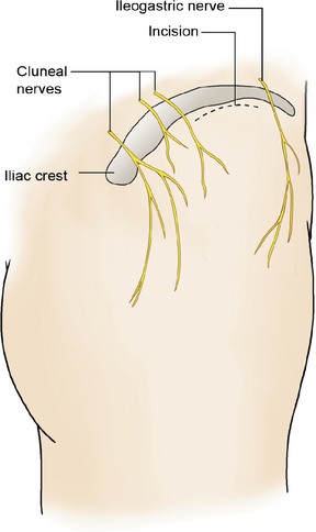
We prefer to place the pocket site for lower extremity stimulation at the upper abdominal wall rather than back below the iliac crest (Fig. 15-23). Placement of the pulse generator (Fig. 15-8) in the buttock region may produce up to a fivefold higher tensile loading than placement in the abdomen or subclavicular area (Fig. 15-24).
We prefer to place the pocket site for upper extremity stimulation at the subclavicular area, because when the pulse generator is implanted at the abdomen, patients may complain of discomfort during movement and because lead migration occurs frequently owing to long distance from the anchor to the pulse generator (Fig. 15-20).
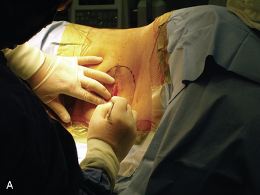
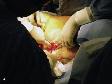
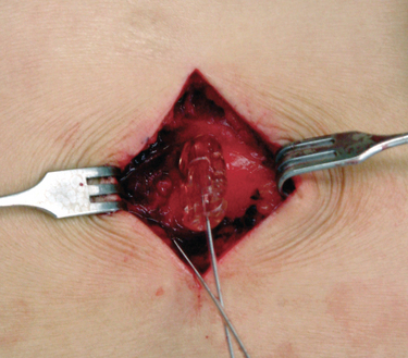
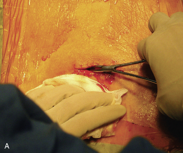
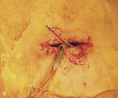
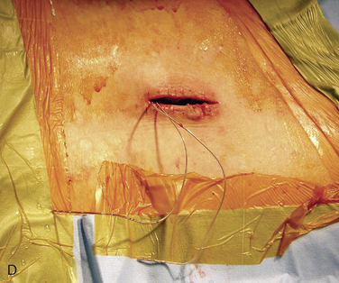
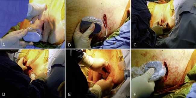
Figure 15–25 Creating a subcutaneous pocket with a linear incision (A) and blunt finger dissection (B).
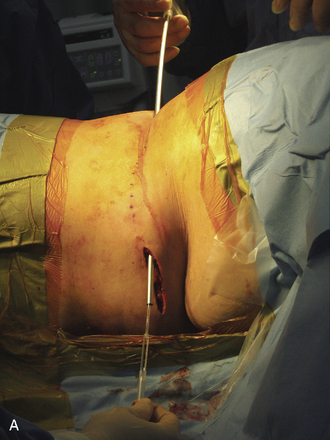
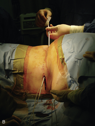
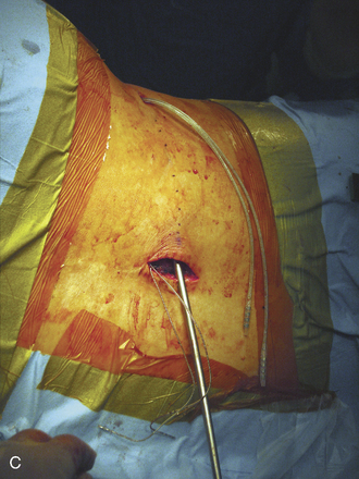
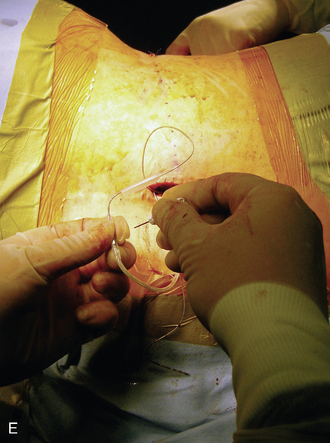
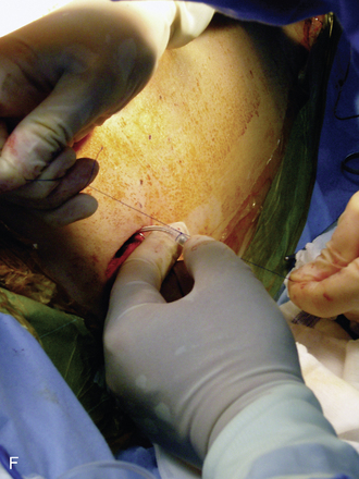
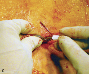
A two-step tunneling technique, from flank incision to the pocket site (Fig. 15-26) and then from the spine incision to the flank incision (Fig. 15-26C), is required in some cases.
Avoiding Complications
Precautions that the operator should make to minimize the risk of technical complications after implantation are as follows [5]:
 Leads should be introduced via a paramedian rather than a midline approach. A shallower angle of introduction is beneficial for lead steering and helps minimize the potential for compression of neural structures due to bending of the relatively stiff lead.


Postprocedural management
Effects of Body Position on Stimulation


Discharging the Patient
Case study 15.1
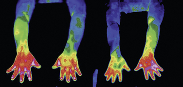
Findings of cervical magnetic resonance imaging, electromyography with nerve conduction study, and bone scan were nonspecific. Digital infrared thermographic imaging of the upper extremities showed significant difference of temperature between the two arms (Fig. 15-29).
The patient was treated with various medications (gabapentin, triazolam, carbamazepine, fluoxetine, and baclofen) as well as interventional pain treatments (cervical epidural steroid injection, ketamine infusion therapy, pulsed radiofrequency lesioning at the cervical dorsal root ganglia, thoracic sympathetic ganglion block [Fig. 15-29], and alcohol neurolysis) without significant pain relief (visual analog scale [VAS] for pain score 9/10).
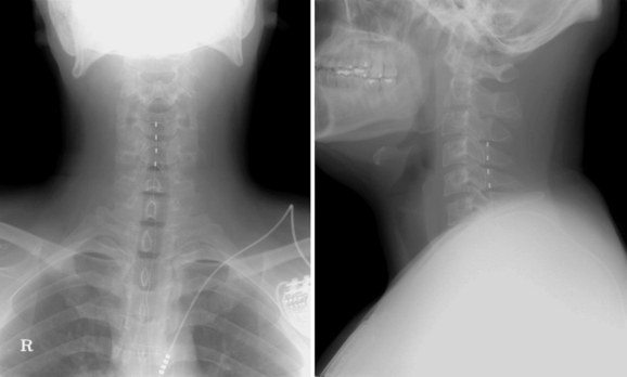
A trial of spinal cord stimulation was performed, and the lead tip was located at the upper end plate of C4 (Fig. 15-30). Paresthesia totally covered the patient’s pain area. He reported significant alleviation of the pain (VAS score 3/10) during the trial period. After 1 week of trial stimulation, the implantation of a pulse generator was performed.
Case study 15.2
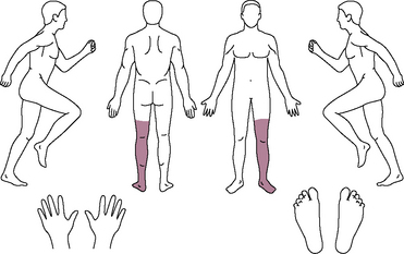
A 23-year-old man presented with left lower leg pain (9/10 on a VAS) below the knee (Fig. 15-31). He had received minor trauma at the left ankle from a fall 5 months before his visit to our pain center. He had received medications and nerve blocks, including lumbar sympathetic plexus block, at other hospitals without alleviation of pain. He was diagnosed with complex regional pain syndrome type I (Fig. 15-32A) and underwent implantation of a spinal cord stimulation pulse generator. Trial stimulation using a single lead was performed. The skin entry site was at the L1-L2 level, and the lead tip was located at the T11 level, which produced concordant paresthesia at the painful area.
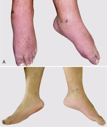
During the 5-day trial, the patient’s VAS pain score was reduced from 9 to 0. Pulse generator implantation was therefore performed using a Pisces-Quad Model 3487 A lead, a Model 7495 Extension, and a Model 7424 Itrel II IPG implanted pulse generator (all manufactured by Medtronic, Inc, Minneapolis, MN) at the left abdominal area. One week after pulse generator implantation, the patient experienced marked reduction of edema and redness (Fig. 15-32B), lower analgesic requirements, greater ability to perform activities of daily living, and improvement in symptoms such as insomnia.
1 Kumar K., Hunter G., Demeria D. Spinal cord stimulation in treatment of chronic benign pain: Challenges in treatment planning and present status, a 22-year experience. Neurosurgery. 2006;58:481-496.
2 Aló K.M., Yland M.J., Redko V., et al. Lumbar and sacral nerve root stimulation (NRS) in the treatment of chronic pain: A novel approach and neurostimulation technique. Neuromodulation. 1999;2:23-32.
3 North R.B., Ewend M.G., Lawton M.T., et al. Spinal cord stimulation for chronic intractable pain: Superiority of “multi-channel” devices. Pain. 1991;44:119-130.
4 Turner J.A., Loeser J.D., Bell K.G. Spinal cord stimulation for chronic low back pain: A systematic literature synthesis. Neurosurgery. 1995;37:1088-1095.
5 Henderson J.M., Schade C.M., Sasaki J., et al. Prevention of mechanical failures in implanted spinal cord stimulation systems. Neuromodulation. 2007;10:82-83.