Chapter 6 Spinal Cord Stimulation
Implantation Techniques


 Careful planning is essential to successful outcomes when utilizing SCS systems. Planning includes appropriate patient selection; trialing technique; lead type and location; and generator type and location.


Patient Selection
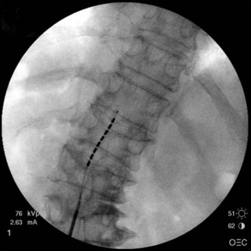
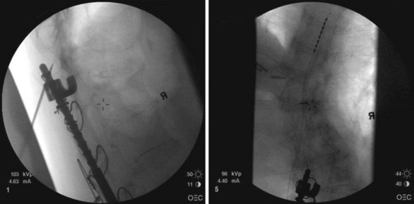
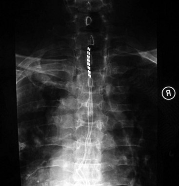
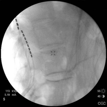
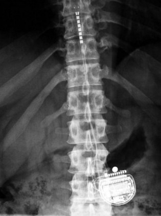
Patient selection for SCS is reviewed in detail elsewhere in this book. The ideal candidates for percutaneous leads are younger patients who do not have significant degenerative spine disease or pronounced scoliosis and/or kyphosis. The patients depicted in Figs. 6-1 and 6-2 have significant scoliosis and were considered potentially difficult percutaneous placements. Approaching from the convex side of the scoliotic curve, the trials proceeded uneventfully as did the subsequent permanent percutaneously placed epidural leads.
Migration of percutaneously placed spinal cord stimulator leads has been reported in many studies.1–3 The reported incidence ranges from 5% to 23% in different series.1–4 Proper patient selection should help to minimize the likelihood of subsequent migration. As with morbidly obese patients, very thin patients may prove more technically challenging for the percutaneous implanter. This may include finding appropriate space for the generator and anchors and fixation of the leads.
Trialing
How much pain relief is necessary before considering a trial successful for subsequent permanent implant? The literature often reports 50% pain relief as an outcome for judging a successful trial.5–6 No good studies have looked at whether a criterion of 50% pain relief during a trial period predicts long-term success with SCS. It is quite possible that some patients with less than 50% relief may find acceptable relief long term and/or significant improvement in activities of daily living and increased functional abilities. It is known that some patients who report 50% or greater pain relief during a trial do not sustain relief long term and eventually become therapy failures.
Risk of infection during spinal cord stimulator trial has been infrequent.7–8 Meticulous sterile technique should be followed during the trial placement. Literature from other implantable trial catheters suggest that the risk of infection increases with the duration of the trial.9 A recent study with intrathecal catheters (in which the risk of serious neuraxial infection would be expected to be greater than epidurally placed spinal cord stimulator leads) reported no infections until week 3 and thereafter an incidence of 16% for catheters placed longer than 2 weeks.9
Positioning the Spinal Cord Stimulator Lead
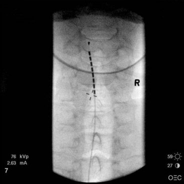
After sterile surgical preparation (e.g., chlorhexidine), many implanters use an Ioban drape over the surgical site. Standard sterile surgical techniques are used. Needle entry for percutaneous placement depends in part on anticipated final placement of the lead(s). Common needle entry for the lower extremity and/or axial low back pain is the midlumbar region. Skin entry commonly is marked at L2-3, L3-4, or L4-5. Entry into the epidural space should be as flat as possible, dependent in part on the body habitus of the patient. Entry into the epidural space is either one or often two levels above skin insertion. A paramedian approach should be used to avoid both the forces of the supraspinous and interspinous ligaments and the tendency of the spinous process to fracture a lead placed through a midline approach. The percutaneous implanter should not hesitate to use a longer-than-standard epidural needle to ensure that the angle of approach to the epidural space is shallow (less than 45 degrees whenever possible). A lateral view should be taken to ensure that the lead has not migrated anteriorly in the epidural space or into the dura (Fig. 6-3).
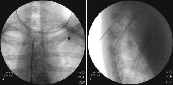
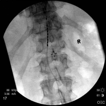
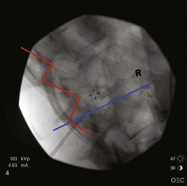
Common lead placement for lower-extremity paresthesias vary from T9 to T12 (Figs. 6-4 and 6-5). Lead placement below T12 will not consistently stimulate posterior columns since the spinal cord often terminates at L1 or L2. Stimulation for axial back paresthesias commonly requires placement of the leads at T7 and/or T8. As stated previously, final lead placement should always be individualized to the patient response during intraoperative mapping.
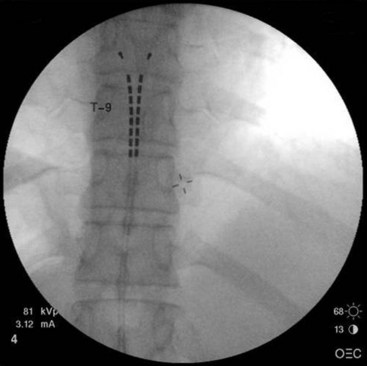
Fig. 6-4 Lead placement for typical spinal cord stimulation of lower extremities and axial back pain.
For upper-extremity paresthesias, leads are commonly placed from C2 to C7. Needle insertion should be in the thoracic region. A choice exists between the upper and lower thoracic region. The upper thoracic area is a stable and good site for needle placement. Skin location of T4 or T5 allows the needle to advance easily in a shallow orientation to the epidural space. The normal kyphotic nature of the upper thoracic spine can make insertion in this area technically difficult or nonintuitive to the novice implanter. On the skin the needle often appears perpendicular, whereas the fluoroscopic image (particularly the lateral image) verifies that the approach to the epidural space is shallow (Fig. 6-6). Although insertion at T3 or T2 is certainly achievable, this kyphotic tendency enhances the direction of the needle. Skill and practice in learning this technique are necessary before implementation. The lateral view on fluoroscopic imaging can be difficult to interpret (see Fig. 6-6). However, as described in the following paragraphs, there are significant advantages to using the lateral view as one advances the needle in this location. With practice, the implanter can learn to interpret and understand this approach in the lateral view. The major advantage of needle placement in this area is less threading or passing of the electrode lead in the epidural space.
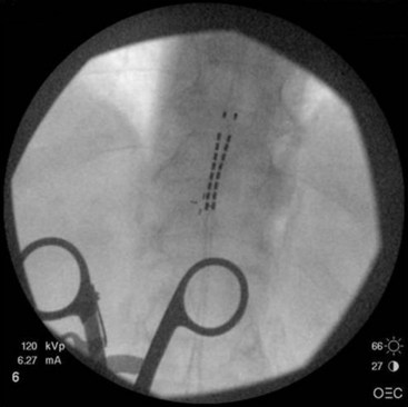
In our practice we use a lower thoracic approach when the patient is young or we expect threading or passing of the lead in the epidural space to proceed without difficulty. In the older patient or one with significant spine disease we commonly choose the upper thoracic space for needle entry. Passing the lead(s) long distances through the thoracic spine region in the presence of significant spondylolysis, facet arthropathy, spurs, thickened ligamentum flavum, or other degenerative diseases can be technically challenging and fraught with difficulty. The lead can bow when significant obstructions are encountered, with painful paresthesias reported by the patient if the lead contacts a corresponding nerve root (Fig. 6-7).
In our experience it can be very difficult to obtain adequate paresthesias with SCS in patients who have significant neck pain. The best attempt at achieving paresthesia relies on placement of the electrode at C2 with an exaggerated lateral location as seen on the anteroposterior (AP) fluoroscopic image (Fig. 6-8). One alternative is to attempt a trial with a paddle lead placed retrograde over C1-C2, in a midline position. In the experience of the authors, this often allows for paresthesia coverage of the neck.
There have been case reports demonstrating four-limb paresthesias with leads placed in the lower cervical region.10 Most patients considered candidates for SCS do not have pain in three to four extremities. However, this observation of four-limb stimulation has been useful in the rare patient and may prevent placement of a second generator and two additional leads.
Lead placement for angina pectoris patients is commonly performed at C7 to T3 (Fig. 6-9). Needle insertion is usually in the lower thoracic level (T9 to 12). Two leads are commonly used and are positioned over both posterior columns. The leads should be placed close to the midline to avoid uncomfortable paresthesias of the chest wall.
A note should be made about the placement of two percutaneous leads. For trial purposes, the second needle is sometimes placed on the opposite side of the spine from the first needle or an interspace one level below the first needle. One should avoid placing the second needle above the first needle on the same side of the spine because the needle can potentially damage the lead coming from the first needle (Fig. 6-10). It is possible to use the same interspace as the first needle, use a skin insertion site 1 to 2 cm below the first needle, and approach the space using the first needle as a guide.
Subcutaneous Cut-Down and Lead Anchoring Techniques
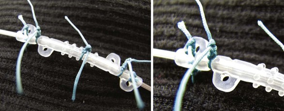
Meticulous anchoring of the leads is essential to prevent subsequent migration of the lead array. Anchoring devices are preferred by the authors as sutures placed directly around the leads may facilitate lead deterioration, failure, and possibly fracture. Nonabsorbable sutures placed into deep fascial planes help hold the anchor in place. Multiple sutures around some of the anchoring devices help to minimize subsequent migration (Fig. 6-11). When using an anchoring sleeve, it should be positioned forward on the lead such that the distal end is abutting or directed into the deep fascial tissue. Placement of the anchor in this fashion minimizes the chance of the lead migrating out of the epidural space and into the space between the fascial tissue and the anchoring sleeve. It is a good idea to take frequent fluoroscopic images during the anchoring process to ensure that no lead migration occurs. A final fluoroscopic image in both the AP and lateral views at the end of this process ensures that there has been no migration.
Lateral Fluoroscopic Imaging
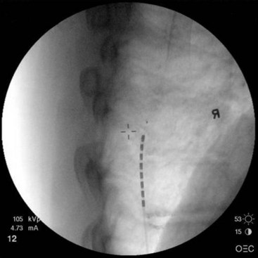
Further, the lateral fluoroscopic view shows where the lumbar lamina is and where access to the epidural space can be gained (Fig. 6-12). If the implanter learns the anatomy and understands the images, it becomes possible to predict if the approach of the needle will gain access to the epidural space or require redirection to avoid the protective lamina.
Generator Site Location and Preparation
An alternative location for the generator is in the flank. This location allows for placement of the generator lateral to where the leads are anchored in lumbar epidural insertions. Large generators are not well tolerated in this area. However, small (rechargeable) generators work very well in a lateral flank location. Fig. 6-13 shows final lead placement with generator positioned in the flank. Flank locations make it unnecessary to have two incisions. This should reduce the risk of skin or superficial infections. In addition, no tunneling is necessary between leads and pocket site. The implanter must make the pocket large enough so the generator stays off the midline area. Patients do not tolerate pockets migrating over the spinal processes. Besides anchoring the generator to fascial tissue, an additional two or three retaining sutures to close the pocket site help keep the generator from migrating.
Paddle/Plate Leads
Cylindrical leads, inserted percutaneously through a Touhy needle or through superficial incisions as discussed in previous paragraphs, are a less invasive option. Incisions are small and typically do not breach the fascia. The advantages of this technical option include limited postoperative pain, discomfort, and length of stay. Most patients can be discharged on the same day as the procedure. Implantation of percutaneous leads is routinely done under local anesthesia with or without intravenous sedation. This minimizes anesthesia-related risk, particularly in the elderly and in those with multiple co-morbidities. However, the design limitations inherent in a cylindrical lead may limit stimulation efficacy. The tips of percutaneous leads are frequently placed several segments rostral to the spinal entry level and then anchored at the point of entry. Although technique modifications11 and improved anchoring devices may limit longitudinal lead migration, lateral lead migration, not always easily identifiable in x-ray films, remains a concern. Furthermore, cylindrical leads are prone to positional effects with changes in activity or posture. This often limits efficacy and practical clinical value in patients who are (or want to be) more active and in those who continue to work.
Plate leads are a valuable alternative to cylindrical leads. Unlike cylindrical leads, plate leads have contacts that are insulated on one side. The contacts are flat and therefore cover a greater surface area. The expanded electrode-tissue interface maximizes efficiency and requires lower stimulation amplitude to generate a similar therapeutic response.12 In 2005, North and associates12 reported a prospective study comparing 12 patients implanted with cylindrical leads to 12 patients implanted with plate leads for the management of failed back surgery syndrome. Patients with plate leads had significantly better clinical results than those with cylindrical leads at 1.9 months follow-up.2 Similarly in a retrospective study Villavicencio and colleagues13 reported that patients implanted with paddle leads also had improved pain control. Lead migration and positional effects observed with cylindrical leads are minimized with the flat or semicurved lead body design of the plate lead. Depending on the model, the lead body can be anchored to spinal elements, or extensions from the lead body can be anchored to the muscle or fascia during wound closure. These anchoring options provide stabilization points that are closer to the electrical contacts than with cylindrical leads. The risk for lead migration is reduced, although migration can still occur in some cases, particularly at the nonanchored distal tip of the lead.
Implantation Technique
The technique for implantation of a paddle lead is sometimes straightforward for the experienced surgeon. However, revision surgery is often challenging. Imaging of the spine can be helpful to assess the size of the canal and evaluate the degree of degenerative disease or post-surgical changes that may influence the type of lead selected and implant strategy. As for other posterior thoracic or cervical spinal procedures, there is always a concern for spinal cord injury, dural tears, or other complications.3,14–16 In this chapter we focus on the thoracic implantation of plate leads in two common scenarios: (1) implantation of the plate lead following a temporary test with a percutaneous cylindrical lead, and (2) implantation of a plate lead after removing chronically implanted SCS cylindrical leads.
Implantation of a New Plate Spinal Cord Stimulator Lead
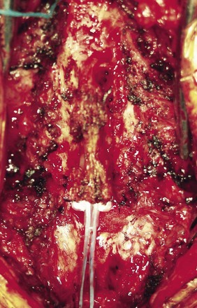
The procedure can be performed under general anesthesia or sedation, with or without regional anesthesia.17–20 If the implant is done under sedation, intraoperative testing of the pattern of paresthesia coverage can be verified during the procedure, in a fashion similar to that of implantation of percutaneous leads.18,20 The plate leads can be adjusted until the induced paresthesias cover all or the majority of the area of chronic pain. Implantation under general anesthesia is often preferred. Reasons include patient choice and concerns for deep sedation in the prone position. Although this option precludes intraoperative testing, implantation of the plate lead can often be successfully accomplished with intraoperative radiographic verification by placing the lead in the topographical region that was adequate for stimulation during the test period. Intraoperative neurophysiological monitoring is often used as for other spine procedures. If, after surgery, paresthesias cannot be created in the areas of chronic pain, revision of the lead may be required to accomplish this goal. The posterior elements of the spine are exposed with standard surgical exposure techniques. The length of the incision may vary with the patient’s body habitus, and usually it is not necessary to extend the dissection as laterally as for spinal instrumentation. Depending on the lead type and planned level of implantation, a unilateral partial laminectomy or laminotomy of the inferior margin of a lamina, sparing the spinous process and supraspinal ligament, is performed. For some lead models and for midline implantation, the exposure may be extended to include a midline partial laminectomy or laminotomy to clear an opening that allows for safe passage. Under most circumstances the tip of the paddle lead is advanced into the canal until the length of the lead is just beyond the laminotomy (Fig. 6-14).
Epidural adhesions, osteophytes, or thickening of the ligamentum flavum can cause resistance when the lead is passed. The nerve roots or the dural sac may also block lead advancement. In these situations it is often necessary to remove the lead and attempt reimplantation until a satisfactory trajectory into the canal and final location are seen. The dural guide is a useful instrument to facilitate dissection. Some plate lead kits include a tool for dissection of epidural adhesions. When resistance is identified, fluoroscopy can be helpful to identify what level and structure may be causing the resistance. For example, if the lead is directed laterally, resistance may be related to a nerve root, and repeated attempts may result in damage to the root or dural tear. In addition, forcing the lead beyond resistance could push it toward the sac and result in tear or cord injury. Complications from dissection of the sublaminar epidural space and lead placement are not limited to direct injury to the cord and roots during dissection alone. Hematoma formation,21 inadvertent dural tear with leakage of cerebrospinal fluid, and pseudomeningocele formation are infrequent but recognized complications for this type of operation.
The lead can be anchored directly to the ligamentum flavum. Anchoring to the dura can be attempted, but the suture through the dura may create fluid leakage. Some leads have a portion of the body configured for suture anchoring. If the lead is not anchored directly to the spinal elements, the extensions from the lead body can be anchored to the soft tissues during closure. Some anchors provided with the SCS leads or in separate packages are designed for this purpose. Different anchoring techniques and anchoring devices can be used. Bench data have suggested that the position and type of anchor may influence the stress on the lead and promote hardware failure,14 although these findings have not yet been validated clinically. Implantation of the implantable pulse generator (IPG) and connection to the lead directly or via extension wires is performed in a similar fashion as described for cylindrical leads.
Implantation of a Spinal Cord Stimulator Plate Lead After Removal of Cylindrical Leads
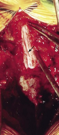
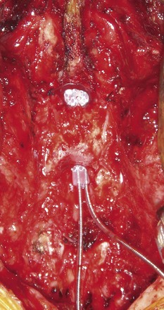
Patients experiencing limited benefits or complications associated with cylindrical lead implantation such as migration, positional effects, or hardware failure are often referred for revision of the SCS system and implantation of a paddle lead replacing the cylindrical leads. If cylindrical lead migration or limited benefits are observed early, before extensive scar formation, replacement with a plate lead is less complicated. The complexity and risk of the operation increases over time as scar formation around the cylindrical leads thickens. Computed tomography myelograms may be of value to assess the lead location and canal dimensions when revision surgery is planned. Magnetic resonance imaging is not possible in patients implanted with current SCS systems. Surgical exposure is essentially the same as for a new lead; however, caution (or avoidance) must be used with Bovie electrocautery in a patient already implanted with a neurostimulation system. The cylindrical leads are removed from their entry and anchoring site. The laminectomy is planned in accordance with the intended level of implantation of the lead. The scar buildup around the previously implanted leads may be obvious in the epidural space (Fig. 6-15). Dural guides and implantation tools for clearing the sublaminar space can be used to dissect epidural scar. If significant resistance is noted with passing the lead and the epidural scar is resistant to dissection, another laminotomy may be opened one or two levels cranially to facilitate dissection of the epidural scar and adhesions. In some cases a full laminectomy is needed. This should be weighed against the risk of a late deformity. However, if at least a “bridge” of lamina can be preserved, it can assist in stabilizing the lead and preventing dorsal migration away from the dura (Fig. 6-16).
1 Barolat G. Spinal cord stimulation for chronic pain management. Arch Med Res. 2000;31:258-262.
2 North RB, et al. Spinal cord stimulation electrodes design: a prospective, randomized controlled trial comparing percutaneous with laminectomy electrodes: part II-clinical outcomes. Neurosurgery. 2005;57:990-996.
3 Cameron T. Safety and efficacy of spinal cord stimulation for the treatment of chronic pain: a 20-year literature review. J Neurosurg. 2004;100:254-267.
4 Kumar K, et al. Spinal cord stimulation versus conventional medical management: a multicenter randomized controlled trial of patients with failed back surgery syndrome. Pain. 2007;132:179-188.
5 Kapural L, et al. Spinal cord stimulation for chronic visceral pain. Pain Med. 2010;11:347-355.
6 Jang HD, et al. Analysis of failed spinal cord stimulation trials in the treatment of intractable chronic pain. J Korean Neuro. 2008;43:85-89.
7 Rauchwerger JJ, et al. Epidural abscess due to spinal cord stimulation trial. Pain Pract. 2008;8:324-328.
8 Kumar K, Wilson JR. Factors affecting spinal cord stimulation outcome in chronic benign pain with suggestions to improve success rate. Acta Neurochir. 2007;97(suppl):91-99.
9 Wallace MJ, et al. Intrathecal ziconotide for severe chronic pain: safety and tolerability results of an open-label, long-term trial. Anesth Analg. 2008;106:628-637.
10 Hayek S, Veizi ID, Stanton-Hicks M. Four-limb neurostimulation with neuroelectrodes placed in the lower cervical spine. Anesthesiology. 2009;110:681-684.
11 Renard VM, North RB. Prevention of percutaneous electrode migration in spinal cord stimulation by a modification of the standard implantation technique. J Neurosurg Spine. 2006;4(4):300-303.
12 North RB, et al. Spinal cord stimulation electrode design: prospective, randomized, controlled trial comparing percutaneous and laminectomy electrodes-part I: technical outcomes. Neurosurgery. 2002;51(2):381-389.
13 Villavicencio AT, et al. Laminectomy versus percutaneous electrode placement for spinal cord stimulation. Neurosurgery. 2000;46:399-406.
14 Kumar K, et al. Complications of spinal cord stimulation, suggestions to improve outcome and financial impact. J Neurosurg. 2006;5:191-203.
15 Turner JA, et al. Spinal cord stimulation for patients with failed back surgery syndrome or complex regional pain syndrome: a systematic review of effectiveness and complications. Pain. 2004;108:137-147.
16 Taub A, Collins WF, Venes J. Partial, reversible, functional spinal cord transection: a complication of dorsal column stimulation for the relief of pain. Arch Neurol. 1974;30:107-108.
17 Vangeneugden J. Implantation of surgical electrodes for spinal cord stimulation: classical midline laminotomy technique versus minimal invasive unilateral technique combined with spinal anaesthesia. Acta Neurochir. 2007;97(suppl):111-114.
18 Beems T, van Dongen RT. Use of a tubular retractor system as a minimally invasive technique for epidural plate electrode placement under local anesthesia for spinal cord stimulation: technical note. Neurosurgery. 2006;58:ONS-E177. discussion ONS-E177
19 Garcia-Perez ML, et al. Epidural anesthesia for laminectomy lead placement in spinal cord stimulation. Anesth Analg. 2007;105:1458-1461.
20 Lind G, et al. Implantation of laminotomy electrodes for spinal cord stimulation in spinal anesthesia with intraoperative dorsal column activation. Neurosurgery. 2003;53:1150-1153. discussion 1153-1154
21 Franzini A, et al. Huge epidural hematoma after surgery for spinal cord stimulation. Acta Neurochir (Wien). 2005;147:565-567. discussion 567


