Spinal Cord Stimulation

Published on 06/02/2015 by admin

Filed under Anesthesiology

Last modified 22/04/2025

Print this page

rate 1 star rate 2 star rate 3 star rate 4 star rate 5 star
Your rating: none, Average: 0 (0 votes)

This article have been viewed 1476 times

51 Spinal Cord Stimulation

Perspective

The idea that direct stimulation of the ascending sensory tracts of the spinal cord might interfere with the perception of chronic pain is founded on everyday observations. We are all familiar with the fact that rubbing an area that has just been injured seemingly reduces the amount of pain coming from that injured region. The advent of transcutaneous electrical nerve stimulation (TENS), wherein a light, pleasant electrical current is passed through surface electrodes in the region of ongoing pain, reinforced the observation that stimulation of sensory pathways reduces pain perception in chronic pain states. In 1965, Patrick Wall, a neurophysiologist exploring the basic physiologic mechanisms of pain transmission, and Ronald Melzack, a psychologist working with patients who had chronic pain, together proposed the gate control theory to explain how non-noxious stimulation can reduce pain perception. With their theory, they proposed that second-order neurons at the level of the spinal cord dorsal horn act as a “gate” through which noxious stimuli must pass to reach higher centers in the brain and be perceived as pain. If these same neurons receive input from other sensory fibers entering through the same set of neurons in the spinal cord, the non-noxious input can effectively close the gate, preventing simultaneous transmission of noxious input. Thus, the light touch of rubbing an injured region or the pleasant electrical stimulation of TENS closes the gate to the noxious input of chronic pain. Based on this theory, investigators developed the concept of direct activation of the ascending fibers in the dorsal columns that transmit nonpainful cutaneous stimuli (e.g., light touch) as a means of treating chronic pain. We have learned much about the anatomy and physiology of pain perception since the gate control theory was first proposed. It is unlikely that the simplistic notion of a gate in the dorsal horn is responsible for our observations, but the theory served as a useful concept in the development of spinal cord stimulation. Both the peripheral nerve fibers and second-order neurons in the dorsal horn that transmit pain signals become sensitized after injury, and anatomic changes, cell death, and altered gene expression are all likely to have a role in the development of chronic pain. Direct electrical stimulation of the dorsal columns, referred to as spinal cord stimulation (SCS) or dorsal column stimulation, has proven effective, particularly in the treatment of chronic radicular pain. The mechanism remains unclear, but direct electrical stimulation in the dorsal columns may produce retrograde changes in the ascending sensory fibers that modulate the intensity of incoming noxious stimuli.

Patient selection for SCS is empiric and remains a subject of some debate. In general, SCS is reserved for patients with severe pain that does not respond to conservative treatment. The pain responds best when it is relatively well localized because the success of SCS depends on the ability to cover the entire painful region with electrical stimulation. Attaining adequate coverage is more difficult when pain is bilateral, often requiring two leads, one on each side of the midline. When the pain is diffuse, it may be impossible to obtain effective coverage with stimulation using SCS. Among the best-established indications for SCS is chronic radicular pain with or without radiculopathy in either the upper or lower extremities. Use of SCS to treat chronic, axial low-back pain has been less satisfactory, but recent results seem more promising with the advent of dual-lead systems and electrode arrays that allow for a broad area of stimulation. Randomized controlled trials comparing SCS with repeat surgery for patients with failed back surgery syndrome have demonstrated greater success in attaining satisfactory pain relief in those treated with SCS. Recent small randomized controlled trials also suggest significantly improved pain relief and physical function in patients with complex regional pain syndrome who are treated with SCS in conjunction with physical therapy compared with physical therapy alone. Prospective observational studies indicate an overall success rate of about 50% (defined as at least 50% pain reduction and ongoing use of SCS 5 years after implantation) in mixed groups of patients with ongoing low-back or extremity pain (or both) after lumbar surgery. The usefulness of psychological screening before SCS remains controversial; some investigators have suggested that screening for patients with personality disorders, somatoform disorder, or hypochondriasis may improve the success rate of SCS.

Once a patient is selected for therapy with SCS, a trial is carried out. Most physicians now conduct trials by placing a temporary percutaneous epidural lead and conducting the screening using an external device as an outpatient procedure to judge the effectiveness of this therapy before a permanent system is implanted. Some carry out the SCS trial using a surgically implanted lead that is tunneled using a lead extension that exits percutaneously. The strictly percutaneous trial lead is simpler to place and does not require a full operating room setup, but the lead must be removed and replaced surgically after a successful trial. The surgically implanted trial lead requires placement in the operating room, with surgical removal if the trial is unsuccessful. If the trial is successful, the implanted trial lead can remain, and the second procedure to place the impulse generator is brief, not requiring placement of a new epidural lead. In either case, after successful trial stimulation, a permanent system is placed and the lead is positioned to produce the same pattern of stimulation that afforded pain relief during the trial stimulation.

Placement

Anatomy

The epidural SCS lead is placed directly into the dorsal epidural space just to one side of the midline using a paramedian, interlaminar approach. Entry into the epidural space is performed several levels below the final intended level of lead placement. Typically, leads for stimulation of the low back and lower extremities are placed through the LI-L2 interspace, and those for upper extremity stimulation are placed through the C7-T1 interspace. Investigators have mapped the patterns of electrical stimulation of the dorsal columns and the corresponding patterns of coverage reported by patients with leads in various locations. In general, the epidural lead must be positioned just 2 to 3 mm to the left or right of the midline on the same side as the painful region to be covered. For lower extremity stimulation, successful coverage is usually achieved by placing the lead between the T8 and T10 vertebral levels, whereas upper extremity stimulation usually requires lead placement between the occiput and C3 vertebral levels. If the lead ventures too far from the midline, uncomfortable stimulation of the spinal nerves may result. If the lead is placed too low, overlying the conus medullaris (at or below Ll-L2), unpredictable patterns of stimulation may result. In the region of the conus, the fibers of the dorsal columns do not lie parallel to the midline; rather, they arc from the corresponding nerve entering the spinal cord toward their eventual paramedian location several levels cephalad.

Position

A percutaneous trial spinal cord stimulator lead can be placed in any location that is suitable for epidural catheter placement. This procedure may be done in the operating room but can easily and safely be carried out in any location that allows adequate sterile preparation of the skin and draping of the operative field and that has fluoroscopy available to guide anatomic placement. In a strictly percutaneous trial, the trial lead is placed in the same fashion as that used for permanent lead placement, but the lead is secured to the skin without any incision for the trial period.

Before permanent spinal cord stimulator implantation, one must discuss with the patient the location of the pocket for the impulse generator. The most suitable regions are the lower quadrant of the abdomen and the lateral aspect of the buttock. Once the site is determined, the proposed skin incision is marked with a permanent marker while the patient is in the sitting position. The position of the pocket is deceptively difficult to determine once a patient is lying on his or her side. If the location is not marked, the pocket is often placed too far laterally in the abdominal wall or buttock. Placing the impulse generator in the buttock allows the entire procedure to be carried out with the patient in the prone position and simplifies the operation by obviating the need to turn from the prone to the lateral position halfway through implantation.

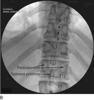
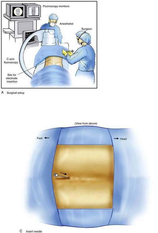
Implantation of a spinal cord stimulator lead and impulse generator is a minor surgical procedure that is carried out in the operating room using aseptic precautions, including skin preparation, sterile draping, and full surgical attire (Fig. 51-1A). The procedure must be conducted using local anesthesia and sedation light enough that the patient can report feeling the electrical stimulation during lead placement. The patient is positioned on a radiolucent table in the prone position (see Fig. 51-1A). Initial lead placement can be carried out with the patient in a lateral decubitus position, but even small degrees of rotation along the spinal axis can make positioning the lead difficult. The arms are extended upward so that they are in a position of comfort well away from the surgical field. The skin is prepared, and sterile drapes are applied. For stimulation in the low back and lower extremities, the fluoroscopic C-arm is positioned directly over the thoracolumbar junction to provide an anteroposterior view of the spine. Care must be taken to ensure that the radiographic view is not rotated by observing that the spinous processes are in the midline, halfway between the vertebral pedicles (Fig. 51-1B).

image image image image image

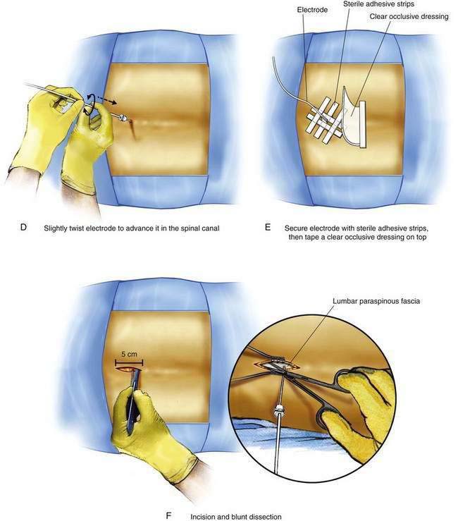
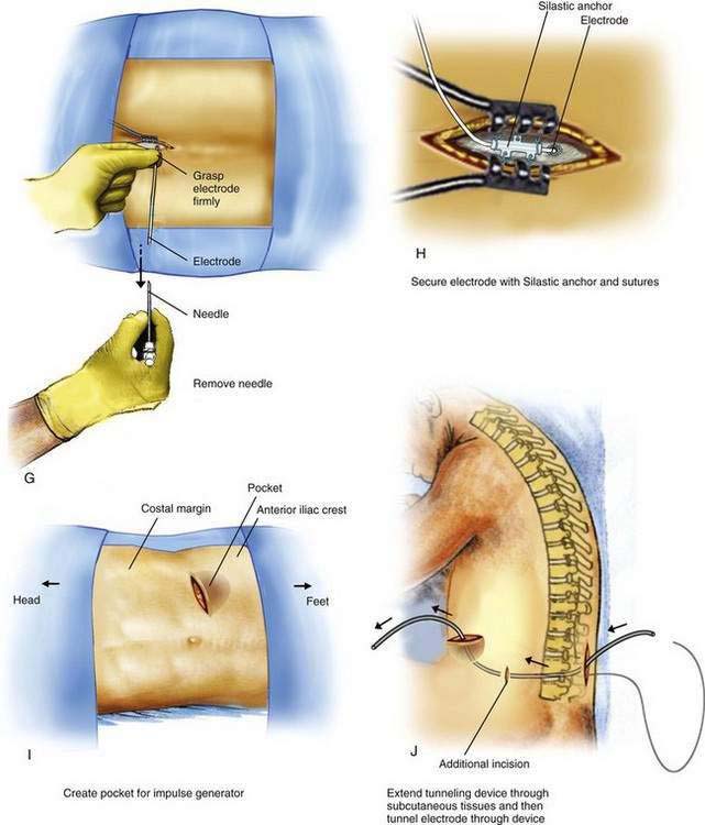
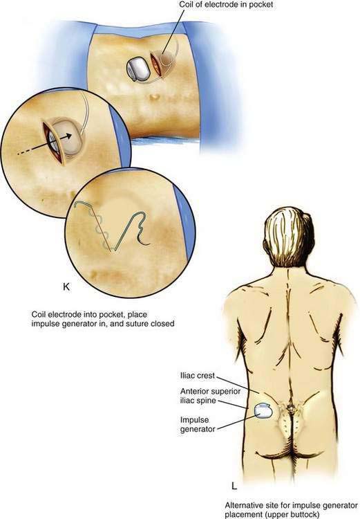
Figure 51-1. Spinal cord stimulator trial and permanent implantation. A, View of a typical operating room arrangement during spinal cord stimulator implantation; the patient is placed in the prone position with the fluoroscopic C-arm in place for an anteroposterior (AP) view of the thoracolumbar spine. B, Posteroanterior radiograph of a spinal cord stimulator lead in position for stimulation of the right lower extremity. The lead lies to the right of midline, with the tip over the inferior endplate of the T9 vertebral body. During initial patient positioning, care must be taken to ensure that the image is in the AP plane without rotation by moving the image intensifier in the mediolateral direction until the spinous processes project midway between the pedicles. C, Initial epidural needle placement at the L1-L2 interspace using a paramedian approach. The angle of entry into the epidural space must be less than 45 degrees relative to the plane of the epidural space to ensure that the lead can pass easily. D, The electrode is advanced under continuous fluoroscopic guidance using a slight twisting motion to steer the catheter to the desired position just lateral to the midline on the side of the desired stimulation. E, For trial stimulation using a percutaneous lead, the lead is secured to the back using either sutures or sterile adhesive strips; a sterile occlusive dressing is then placed. F, A cephalocaudad incision is made through the skin and subcutaneous tissues, with the incision extending above and below the needle entry point. Using blunt dissection, the skin and subcutaneous tissues are further divided until the lumbar paravertebral fascia is exposed. G, The needle and stylet are removed together while the lead is held firmly in position. H, The lead is secured to the paravertebral fascia using an anchoring device provided by the manufacturer. I, A transverse incision is created in the abdominal wall midway between the umbilicus and the anterior axillary line or over the superolateral aspect of the buttock. A pocket of sufficient size to accommodate the impulse generator is then created using blunt dissection, which can be accomplished using the fingertips or surgical scissors and a repeated spreading (rather than cutting) motion. J, A tunneling device provided by the manufacturer is used to position the lead in the subcutaneous tissue between the paravertebral incision and the pocket. K, After ensuring good hemostasis, the impulse generator is placed in the pocket, with any excess lead coiled loosely and inserted in the pocket, behind the impulse generator. The pocket and paravertebral incisions are then closed in two layers: a layer of interrupted absorbable sutures in the subcutaneous tissue overlying the impulse generator and lead, and a separate layer in the skin. L, The upper buttock, well lateral to the posterior superior iliac spine and sacral prominence, is also a common site for placement of the implanted pulse generator.

Procedure

The Ll-L2 interspace is identified using fluoroscopy. The epidural needle supplied by the device manufacturer must be used to ensure that the lead can advance through the needle without damage. The needle is advanced using a paramedian approach starting 1 to 1.5 cm lateral to the spinous processes and somewhat caudad to the interspace to be entered. The needle is directed to enter the spinal space in the midline with an angle of entry no greater than 45 degrees from the plane of the epidural space (Fig. 51-1C). If the angle of attack of the needle during the initial entry into the epidural space is too great, the epidural lead is difficult to thread as it negotiates the steep angle between the needle and the plane of the epidural space. The epidural space is identified using a loss-of-resistance technique. The electrode is then advanced through the needle and directed to remain just to one side of midline as it is threaded cephalad under fluoroscopic guidance. The electrode contains a wire stylet with a slight angulation at the tip; gentle rotation of the electrode as it is advanced allows the operator to direct the electrode’s path in the epidural space (Fig. 51-1D). For stimulation in the low back and lower extremities, the electrode is initially positioned 2 to 3 mm from the midline on the same side as the patient’s pain between the T8 and T10 vertebral levels (see Fig. 51-1B). Final electrode position is attained by connecting the electrode to an external impulse generator and asking the patient where the stimulation is felt. In general, cephalad advancement results in stimulation higher in the extremity, and caudad movement leads to stimulation lower in the extremity. However, if the lead is angled even slightly from medial to lateral, the pattern of stimulation may change less predictably with movement of the electrode; for example, craniad advancement can lead to stimulation lower in the extremity under these circumstances. The final electrode position should be recorded using radiography so that a permanent lead can be placed in the same position (see Fig. 51-1B). For trial stimulation, the needle is removed, the electrode secured to the back, and a sterile occlusive dressing applied (Fig. 51-1E). The patient is instructed in the use of the external pulse generator and scheduled to return in 5 to 7 days to assess his or her response and to remove the trial lead.

The procedure for initial lead placement for permanent implantation is identical to that for trial stimulation. Once the final lead is in position and the optimal pattern of stimulation confirmed, the lead is secured, a pocket for the impulse generator is created, and the lead is tunneled underneath the skin for connection to the impulse generator. After initial lead placement, the epidural needle is withdrawn slightly (about 1 to 2 cm) but left in place around the lead in the subcutaneous tissues to protect the lead during the subsequent incision and dissection. A 5- to 8-cm incision parallel to the axis of the spine is extended from cephalad to caudad to the needle, extending directly through the needle’s skin entry point (Fig. 51-1F). The subcutaneous tissues are divided using blunt dissection until the lumbar paraspinous fascia is visible surrounding the needle shaft. The stylet is then removed from the lead and the needle is withdrawn, using care not to dislodge the electrode (Fig. 51-1G). The lead is then secured to the paraspinous fascia using a specific anchoring device supplied by the manufacturer (Fig. 51-1H).

If lead placement has been carried out in the prone position and the impulse generator is to be placed in the abdominal wall, the lead must be coiled underneath the skin, the paraspinous incision temporarily closed using staples, and a sterile occlusive dressing applied. The sterile drapes are then removed and the patient is repositioned in the lateral decubitus position with the side where the abdominal pocket is located facing upward. After repeat preparation of the skin and application of sterile drapes, attention is turned to creating the pocket in the patient’s abdominal wall or overlying the buttock (when the impulse generator is placed over the buttock, this site is included in the initial skin preparation and draping).

An 8- to l0-cm transverse incision is made along the previously marked line and a subcutaneous pocket is created using blunt dissection (Fig. 51-1I). The pocket should always be created caudad to the incision; if the pocket is placed cephalad to the incision, the weight of the impulse generator on the suture line is likely to cause wound dehiscence. In many patients, the blunt dissection can be accomplished using gentle but firm pressure with the fingers. It is simpler and less traumatic to use a small surgical scissors to perform the blunt dissection, using repeated opening motions rather than closing or cutting motions that are likely to cut vascular structures and provoke marked bleeding. An alternative to blunt dissection is the use of a monopolar electrocautery device in the “cut” mode, an effective means to carry out the necessary dissection without excessive tissue trauma or blood loss. After the pocket has been created, the impulse generator is placed in the pocket to ensure that the pocket is large enough. The impulse generator should fit completely in the pocket without any part of the device extending into the incision. With the device in place, the wound margins must fall into close apposition. There should be no tension on the sutures during closure of the incision, lest the wound dehisce.

After the pocket creation is completed, a tunneling device is extended in the subcutaneous tissues between the paraspinous incision and the pocket, leaving a small tension-relief loop of lead in the subcutaneous area of the paraspinous dissection (Fig. 51-1J). The electrode is then advanced through the tunnel. Tunneling devices vary and are specific to each manufacturer. The means by which the electrode is connected to the impulse generator also varies by manufacturer; some devices use a lead extension that connects the impulse generator and the lead, and others use a one-piece lead that is connected directly to the impulse generator. After tunneling, the lead or lead extension is connected with the impulse generator. Any excess lead is coiled and placed behind the impulse generator in the pocket (Fig. 51-1K). This loop allows patient movement without placing tension on the distal electrode, causing it to be pulled from the epidural space. The skin incisions are then closed in two layers: a series of interrupted subcutaneous sutures to securely close the fascia overlying the impulse generator in the pocket and the electrode over the paraspinous fascia, followed by skin closure using sutures or staples (see Fig. 51-1K).

Potential Problems

Bleeding and infection are risks inherent to all open surgical procedures. Bleeding in the pocket can lead to a hematoma surrounding the impulse generator that may require surgical drainage. Bleeding along the subcutaneous tunneling track often causes significant bruising in the region but rarely requires treatment. Similar to other neuraxial techniques, bleeding in the epidural space can lead to significant neural compression. Signs of infection in the impulse generator pocket typically appear between 10 and 14 days after implantation but may occur at any time. Some practitioners have reported successful treatment of superficial infections of the incision overlying the pocket with oral antibiotics aimed at the offending organism and close observation alone. However, infections in the pocket or along the lead’s subcutaneous course almost always require removal of all implanted hardware and treatment with parenteral antibiotics to eradicate the infection. Lead and deep tissue infections can extend to involve the neuraxis and result in epidural abscess formation, meningitis, or both.

There is a significant risk of dural puncture during initial localization of the epidural space using the loss-of-resistance technique. The epidural needle used for electrode placement is a Tuohy needle that has been modified by extending the orifice to allow the electrode to pass easily. This long bevel often results in equivocal loss of resistance; it is not uncommon to have minimal resistance to injection along the entire course of needle placement. To minimize the risk of dural puncture, the needle tip can be advanced under fluoroscopic guidance and first seated on the superior margin of the vertebral lamina (taking care to place additional local anesthetic during advancement). In this way, the depth of the lamina is certain and the needle need be advanced only a small distance over the lamina, through the ligamentum flavum, and into the epidural space. Loss of resistance is used only during the final few millimeters of needle advancement over the lamina. If dural puncture does occur, there is no clear consensus on how to proceed. Some practitioners abandon the lead placement and allow 1 to 2 weeks before any reattempt; this approach allows the practitioner to watch for and treat post–dural puncture headache, which is nearly certain to occur. Other practitioners proceed with lead placement through a more cephalad interspace; if post–dural puncture headache ensues and conservative treatment fails, an epidural blood patch is placed at the level of the dural puncture. Spinal cord and nerve root injury during initial lead placement have been reported. Placing the epidural needle and lead in the awake, lightly sedated patient able to report paresthesias should minimize the risk of direct neural injury.

The most frequent complication after spinal cord stimulator placement is lead migration. The first line of defense is to ensure that the lead is firmly secured to the paraspinous fascia. Suturing the lead to loose subcutaneous tissue or fat is not adequate. After surgery, the patient must be clearly instructed to avoid flexion/extension and rotation at the waist (lumbar leads) or flexion/extension and rotation of the neck (cervical leads) for at least 4 weeks after lead placement. Placing a soft cervical collar on those who have had a cervical lead placed provides a ready reminder to avoid movement. Lead fracture may also occur, often months or years after placement. Avoiding midline placement or tunneling the lead across the midline reduces the incidence of fracture caused by compression of the lead on bone. Lead fracture presents as a sudden loss of stimulation and is diagnosed by checking lead impedance using the spinal cord stimulator programmer.

Wound dehiscence and impulse generator migration are infrequent problems. Ensuring that the size of the pocket is sufficient to prevent tension on the suture line at the time of wound closure is essential for minimizing the risk of dehiscence. Subcutaneous collection of fluid surrounding the impulse generator (seroma formation) can be problematic and typically follows generator replacement. Percutaneous drainage of the sterile fluid collection is often successful in resolving the problem.

Pearls

Routine administration of prophylactic antibiotics is warranted before spinal cord stimulator implantation because any infection that does occur may extend to involve the neuraxis. Appropriate agents include cefazolin 1 to 2 g intravenously (IV) 30 minutes before incision, clindamycin 900 mg IV 30 minutes before incision, or vancomycin 1 g IV over 60 minutes before incision. It is important to discuss the location of the impulse generator with the patient before surgery and mark the site using a skin marker with the patient in the sitting position. The operator should consider each patient’s daily activities when selecting a location. For instance, a mechanic who spends much time leaning forward with his abdomen against a vehicle may be bothered by an impulse generator located in the abdominal wall.

Dural puncture is a significant risk during the procedure, and the particular needle used for placing the spinal cord stimulator lead often does not give a clear sign of loss of resistance during advancement. In such cases, the needle should be advanced using fluoroscopic guidance and the needle tip seated on the margin of the lamina immediately inferior to the interspace one is attempting to enter. In this way, the depth of the lamina is certain and loss of resistance is needed only during the final 3 to 5 mm of needle advancement, reducing the risk of dural puncture. If dural puncture does occur during lead placement, one should consider rescheduling the procedure or moving to a more cephalad interspace for lead placement. Post–dural puncture headache is a near certainty with the large-bore needle used for electrode placement, so the operator must be prepared to offer treatment as needed, including an epidural blood patch. Performing an epidural blood patch in the days immediately after spinal cord stimulator implantation has been described, but the risks associated with the approach are uncertain.

To minimize the risk of lead migration, a secure anchor for the lead is needed. The most important point during implantation is securing the lead to the paraspinous fascia. First, the incision must be extended deep enough to expose the fascia; securing the lead to loose subcutaneous tissue or fat is inadequate. Once the fascia is exposed, the lead anchor supplied by the manufacturer is placed over the lead and the anchor is advanced to the point where the lead enters the fascia. The lead anchor is securely fastened to the lead itself, first using sutures around the anchor and lead only. After this is accomplished, one should no longer be able to slide the anchor over the lead. Then, the lead and anchor are sutured securely to the fascia. Patients are advised to avoid bending or twisting for at least 4 weeks after implantation; a soft cervical collar can be placed for those with cervical leads for comfort and as an effective reminder to avoid movement.

It is also important to ensure that the size of the pocket created for the impulse generator is adequate to prevent tension on the suture line after wound closure. Similarly, one should use caution when placing the fascial closure sutures and know where the lead lies at all times to avoid damaging it with the suture needle.

It is good practice to obtain anteroposterior and lateral radiographs of the spine after successful lead placement. The radiographs can serve as a helpful reference when attempting to produce a similar pattern of stimulation during subsequent lead placement or when trying to determine if the lead has migrated. Loss of stimulation may signal lead migration or fracture. The operator should check lead impedance first to detect a lead fracture. Thereafter, radiography and comparison with films obtained at the time of initial lead placement are used to detect lead migration.

Impulse generator battery failure is inevitable and occurs over a broad range (about 1 to 4 years), depending on the stimulation parameters and frequency of use. Approaching battery end-of-life typically begins with intermittent malfunction of the device; the most common malfunction is the device shutting off on its own.