Sequencing of Orthognathic Procedures
Step-by-Step Approach
Maxillofacial surgeons and orthodontists are the primary clinicians who care for individuals who present with jaw deformities, malocclusions, and the associated facial dysmorphologies. When an orthognathic approach is indicated, there are a limited number of basic surgical techniques that are used to facilitate the three-dimensional repositioning of the skeletal units (i.e., the maxilla, the mandible, and the chin region) to achieve desired improvements in head and neck function and to enhance facial aesthetics. By and large, these options include the Le Fort I (Type) osteotomy, with or without segmentation of the down-fractured maxilla; sagittal split ramus osteotomies of the mandible; and an oblique osteotomy of the chin. Each of these three basic osteotomies and its associated fixation techniques has evolved gradually to its current usage (see Chapter 2).1–6
 Video 6 and 7). The approach is described as it is typically executed for the patient who is undergoing all of these procedures simultaneously. An individual’s unique anatomy and clinical presentation may require variations in surgical approaches and sequencing of treatment.
Description and Sequencing of Orthognathic and Other Frequent Simultaneous Procedures: Step-by-Step Approach
Preparation and Draping
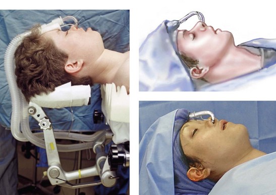
Step 1. The patient is placed supine on the operating room table with the head in a Mayfield (horseshoe) headrest in the neutral neck position.
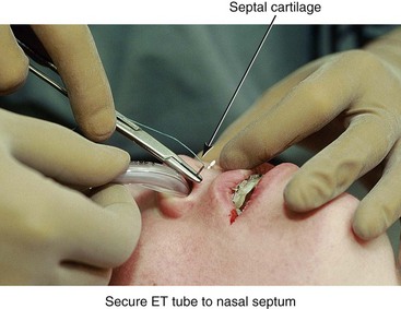
Step 2. A nasotracheal cuffed (Ring-Adair-Elwyn [RAE]) tube is inserted by the anesthesiologist and then secured by the surgeon to the cartilaginous septum with suture (#0 Ethibond). An additional suture (#0 Ethibond) is placed in the midline anterior hair-bearing scalp and then around the endotracheal tube extension over the top of the head to further secure it and to limit tension on the nose (Fig. 15-1).
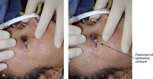
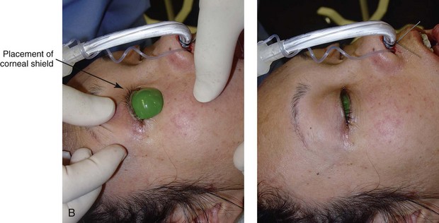
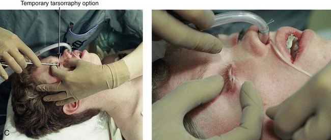
Step 3. Ophthalmic antibiotic ointment and protective corneal shields are placed beneath the eyelids (or temporary tarsorrhaphies are performed, if preferred) to prevent corneal injury during the operation (Fig. 15-2, A through C).
Step 4. The anesthesiologist places monitoring equipment for the safe delivery of deliberate hypotensive anesthesia (i.e., arterial line, Foley catheter, large-bore venous lines, pulse oximeter, carbon dioxide monitor, and temperature probe). The bed is then positioned at approximately 15 degrees reverse Trendelenburg (see Chapter 11).
Step 5. Antibiotics (e.g., Cefazolin (Ancef ); 15 to 20 mg/kg and up to 1 g) and steroids (e.g., Dexamethasone 0.5 mg/kg/dose, max: 8 mg) are administered intravenously by the anesthesiologist.
Step 6. The head and neck are prepped with povidone–iodine (Betadine) solution. Avoid using soap or alcohol solutions that could irritate the cornea and the mucous membranes. Draping should provide for adequate exposure of the forehead, the eyes, the external ears, the face, and the neck. Staples are used to secure the drapes (Fig. 15-3).
Step 7. The mouth and pharynx are suctioned, and a moistened gauze with a radiopaque marker is inserted as a throat pack. The teeth and dorsum of the tongue are cleansed with a sterile toothbrush (1.5% hydrogen peroxide or 0.12% chlorhexidine). The mouth is irrigated with normal saline solution and suctioned.
Step 8. Steroid cream (e.g., betamethasone 0.5%) is applied to the lips to limit edema that could otherwise result from contusion during surgery.
Step 9. Lidocaine solution (Xylocaine 1% with 1 : 100,000 epinephrine) is infiltrated into the lateral vestibules of the mandible, the facial vestibule of the chin, and the labial vestibules of the maxilla.
Cortical Cuts for Sagittal Split Ramus Osteotomies ( Video 6:2 and 7:2)
Step 10. A medium rubber mouth prop is placed between the maxillary and mandibular molars on one side to maintain mouth opening. Attention is turned to the lateral vestibule of the contralateral mandible.
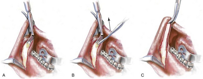
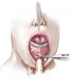
A Incision Option One: No erupted wisdom tooth for extraction. If there is no erupted wisdom tooth to extract (i.e., if the wisdom tooth is fully impacted, absent, or erupted and is to remain in place), an incision is made with a Bovie electrocautery device or a knife (no. 15 blade) in the depth of the vestibule adjacent to the second molar (Fig. 15-4, A). The incision extends both anteriorly and posteriorly for a total length of 4 cm. The incision is carried down to bone. A sufficient cuff of mucosa is maintained adjacent to the gingiva of the molar teeth for relaxed wound closure.
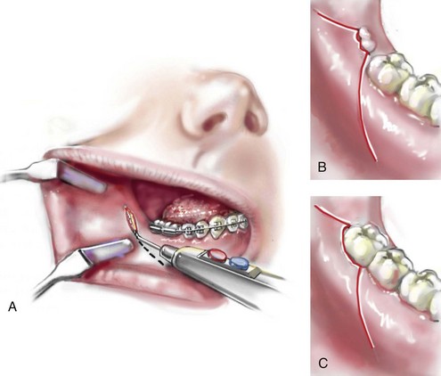
B and C. Incision Option Two: Erupted or partially erupted wisdom tooth for extraction. If there is a partially erupted (Fig. 15-4, B) or fully erupted (Fig. 15-4, C) wisdom tooth to be removed, the incision starts 1 cm distal and lateral to the wisdom tooth and extends to the distobuccal line angle of the tooth. The incision continues anteriorly along the cervical gingival margin of the tooth within the sulcus and then anterior and lateral into the depth of the vestibule. The incision is carried down to bone. A sufficient cuff of mucosa, including part of the papilla, is maintained adjacent to the gingiva of the second molar for relaxed wound closure.
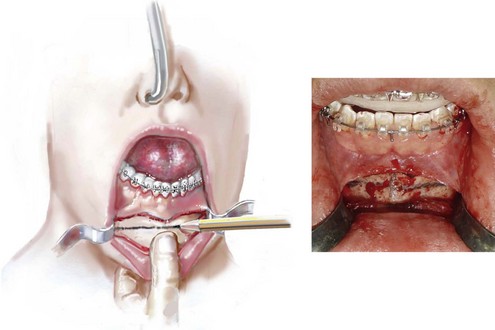
Step 12. The subperiosteal dissection exposes the anterior aspect of the lateral ramus and the posterior body of the mandible down to the inferior border (Fig. 15-5, A). The extent of the dissection anterior to the gonial angle depends on the planned buccal extension of the proximal segment. The dissection exposes the anterior superior aspect of the ramus up toward the coronoid process, with stripping of the temporalis muscle tendon (Fig. 15-5, B C). The dissection exposes the medial aspect of the ramus superior toward the sigmoid notch and inferior toward the mandibular canal (Fig. 15-6, A). (I do not dissect below the inferior alveolar neurovascular bundle or circumferentially around it, because I believe this may cause additional contusion and paresthesia.)
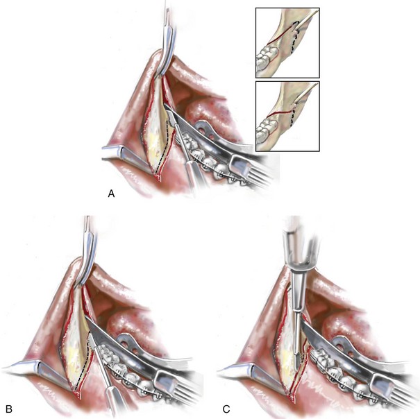
Step 13. Retraction of the soft tissues is performed with a curved Kocher clamp on the coronoid process (superior exposure); a channel retractor superior to the neurovascular bundle (medial ramus exposure); an inferior border retractor placed anterior to the gonial angle (anterior exposure); and a tongue retractor (lingual exposure) (Fig. 15-6).
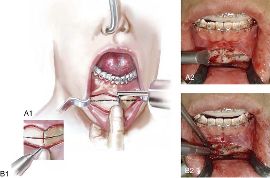
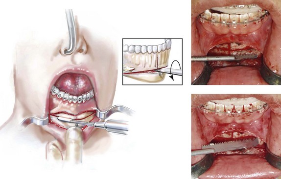
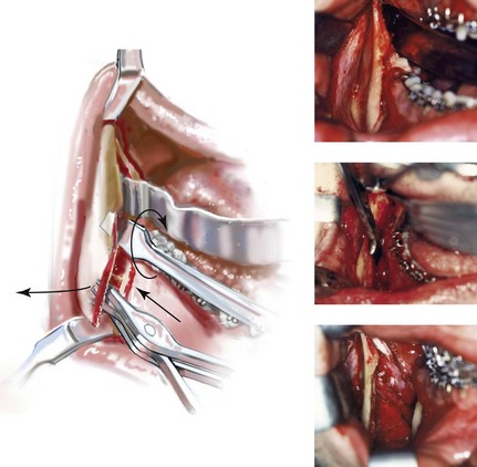
Step 14. With a sterile pencil, the osteotomy lines are marked out for the sagittal splitting of the ramus of the mandible. A reciprocating saw (i.e., with a short, straight blade) completes the cortical osteotomies.
A The first cut is made horizontally through the medial cortex of the ramus. This is judged to be just superior to the occlusal plane of the mandibular molars and well inferior to the region of the anterior aspect of the ramus, where the medial and lateral cortices join and no longer maintain a medullary cavity. The medial osteotomy need not extend more than 2 cm posterior (Hunsuck modification) (see insert of Fig. 15-6, A). By keeping the medial cut “low” (i.e., close to the mandibular molar occlusal surface) and “short” (i.e., only 2 cm back), the incidence of a “bad” split (i.e., with the condyle as a third segment) is greatly reduced.
B The osteotomy then extends anteriorly and just lateral (buccal) to the molars. It is important that the saw blade penetrate the cortex and enter the medullary cavity in all locations. If the wisdom tooth is impacted, the saw blade will bounce off the wisdom tooth just after penetrating the superior paper-thin cortex (Fig. 15-6, B); this will be just lateral to the second molar. The blade will penetrate back into the medullary cavity as the osteotomy progresses anterior past the impacted tooth.
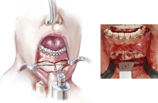
C The reciprocating saw is then repositioned to complete the vertical cortical osteotomy. The osteotomy location will depend on the planned buccal extension of the proximal segment (i.e., the Dal Point modification.) The vertical osteotomy begins at the inferior border of the mandible, where the inferior alveolar nerve is close to the cortex and prone to laceration (Fig. 15-6, C). The osteotomy then continues superiorly to join the cortical osteotomy, which was previously completed lateral to the molars.
 COMMENT: When later “splitting” the ramus (see Steps 53 through 58), as the inferior alveolar nerve enters the mandibular foramen, it may remain within either the proximal segment or the distal segment (see Fig. 15-6, A inset). Traditional thinking is that the medial osteotomy must remain above the mandibular foramen as it extends posterior. I believe that it is more important to keep the medial osteotomy low and short; this is a reliable way to achieve a favorable split with limited risk of the condylar component inadvertently remaining part of the distal segment. After the low and short split is completed, I do not favor the automatic need to completely remove all aspects of the inferior alveolar nerve that may remain within the proximal segment. This is especially true at the mandibular foramen location. I do not drill out or curette the inferior alveolar nerve from the proximal segment unless it would otherwise be under tension after repositioning the distal segment. In my experience, however, this is not usually the case.
Step 15. If the wisdom tooth is erupted and is to be removed, then the extraction is completed now or just before the cortical osteotomies; doing so before the actual split will limit a fracture of the lingual plate that may otherwise occur during dental extraction. A rotary drill with a tapered fissure bur may be used to judiciously remove bone adjacent to the tooth and to section the tooth to facilitate an atraumatic extraction.
Step 16. The wound is irrigated and suctioned. The retractors are removed, and two 1 inch × 3 inch cottonoids are placed for packing (i.e., hemostasis). One is placed along the medial ramus, and the other is placed along the lateral body of the mandible.
Step 17. Attention is turned to the contralateral ramus of the mandible, and identical procedures to those described in Steps 10 through 16 are carried out.
Maxillary (Le Fort I) Osteotomy ( Video 6:3 and 7:3)
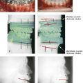
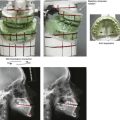
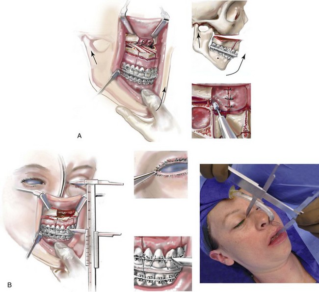
Step 18. With the use of a Tessier caliper, the vertical distance (height) between the medial canthus and the mid-maxillary incisor crown is measured on the left and right sides and recorded; this generally measures between 55 mm and 70 mm (Fig. 15-7). This is a reproducible relative measure of the anterior vertical maxillary height (see Chapter 12).
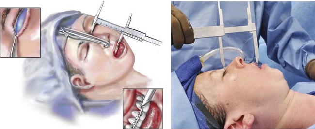
 NOTE: If 70 mm is the baseline measurement and 3 mm of vertical intrusion at the incisors is a surgical objective, then, after maxillary repositioning, 67 mm should be the new measurement before the placement of fixation across the Le Fort I osteotomy.
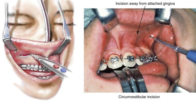
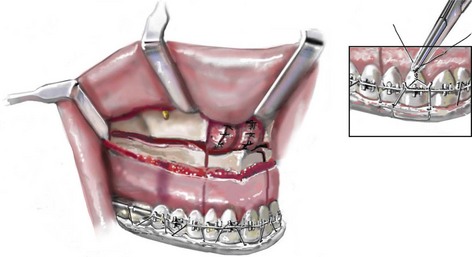
Step 19. Attention is turned to the vestibule of the maxilla on one side. Two medium “toed-in” retractors are used to retract the lip and cheek and thus expose the vestibule. A circumvestibular incision is initiated from the zygomatic buttress region anteriorly toward the midline (Fig. 15-8). It is useful to remain deep in the vestibule and to leave a full cuff of mucosa adjacent to the attached gingiva of the teeth. The most posterior aspect of the incision remains just anterior to and on the dental (vestibular side) of the visualized parotid duct. The incision is made with a Bovie electrocautery device or a knife (#15 blade). Once the incision is made through the mucosa the knife is directed toward the dentoalveolar region and down to bone. This will avoid injury to the infraorbital nerve and limit the exposure of the buccal fat pad.
Step 20. Straight and curved elevators are used for the subperiosteal dissection of the anterior maxilla extending to and on either side of the infraorbital nerve; extending medially to expose the pyriform rim, the floor of the nose, and the anterior nasal spine; and extending posterior to the pterygomaxillary junction. A long “toed-out” retractor is placed subperiosteally in the pterygomaxillary space (Fig. 15-9).
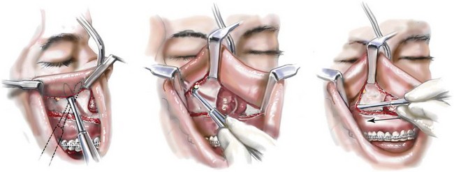
Step 21. The two medium toed-in retractors are shifted to the contralateral side of the maxilla, and the identical incision, dissection, and exposure are accomplished as described in Steps 19 and 20.
Step 22. Straight and curved elevators are used to further separate the nasal mucosa from each lateral nasal wall; the anterior nasal spine from the cartilaginous septum; and the nasal mucosa from the floor of the nose (Fig. 15-10).
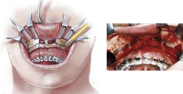
Step 23. With four medium toed-in retractors (one on either side of the infraorbital nerve on each side of the maxilla) and two long toed-out retractors (one in each pterygomaxillary junction) in place, the anterior maxilla is fully visualized. A sterile pencil is used to mark the location for the horizontal Le Fort I osteotomy (Fig. 15-11). If significant maxillary intrusion is planned, a second parallel osteotomy line is marked out. The lower marking (i.e., the osteotomy site) is placed to be within the sinus, above the roots of the teeth, into each lateral nasal aperture, and below each zygomatic buttress. If an ostectomy is to be preformed, the upper marking is made superior and parallel to the lower marking and below the infraorbital nerves (Fig. 15-11).
Segmentation of the Maxilla
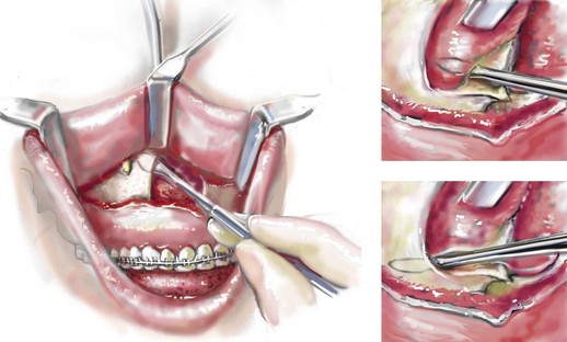
Step 24. If segmentation of the maxilla is to be completed, the interdental osteotomies are initiated before down-fracture. This provides a stable “workbench” for the initiation of each interdental osteotomy. The interdental osteotomies are typically made either between the lateral incisor and the canine on each side (Fig. 15-12, A) or between the central incisors (Fig. 15-12, B). The subperiosteal dissection of the gingival cuff provides adequate exposure of each interdental osteotomy location without the need for direct mucosa incisions. Each interdental osteotomy site is marked with a sterile pencil. The osteotomy is then initiated with an oscillating saw (i.e., a short fan blade on a long shaft) and later deepened after down-fracture with the oscillating saw (i.e., a longer fan blade on a long shaft).
 NOTE: The lateral incisor and canine roots—and, to a lesser extent, the two central incisor roots—are naturally divergent. Therefore, there is no advantage or need for the orthodontist to create a gap for the interdental osteotomy. Perforation into the periodontal ligament space with injury to the dental roots when completing these interdental osteotomies should be an uncommon occurrence.
Maxillary (Le Fort I) Osteotomy: Continued
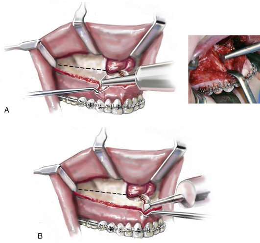
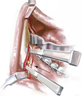
Step 25. With a reciprocating saw (i.e., a long straight blade), the Le Fort I horizontal osteotomy is completed through the lateral, anterior, and medial maxillary walls on each side (Fig. 15-13, A through C). Before the medial maxillary osteotomy is completed, the lateral nasal mucosa is protected with a small malleable retractor placed between the lateral nasal wall and the nasal mucosa. Before the lateral maxillary osteotomy is completed, the pterygoid fossa soft tissues are protected with a long, toed-out retractor.
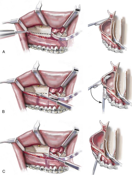
Step 26. With a specialized guarded chisel and mallet, the septum of the nose (i.e., cartilage and bone) is separated from the maxilla. Care is taken to avoid penetration past the septum into the nasopharynx (Fig. 15-14).
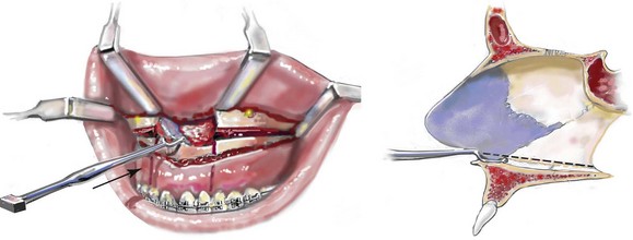
Step 27. With a specialized curved chisel and mallet, the pterygomaxillary suture is separated on each side (Fig. 15-15). Care is taken to avoid injury to the internal maxillary artery or to the pterygoid plexus and to avoid perforation through the palatal mucosa. For a patient with extreme maxillary hypoplasia (e.g., Treacher Collins syndrome), the chisel may be within millimeters of the optic foramen and the optic nerve.
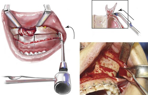
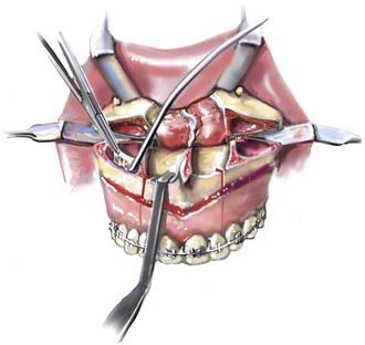
Step 28. With a Tessier (blunt) zygomatic hook placed on the ledge of the nasal sill, force is applied to “down-fracture” the Le Fort I osteotomy unit. While down-fracturing, a Frazier suction tip and a periosteal elevator are used by the assistant to further separate and to limit the tearing of the nasal mucosa (Fig. 15-16).
Step 29. After down-fracture, the maxillary sinus mucosa is generally stripped off of its bony surfaces with a Frazier suction tip and a hemostat (Fig. 15-17). This is done to remove chronic inflammatory tissue (polyps) from the sinus and to reduce hemorrhage.
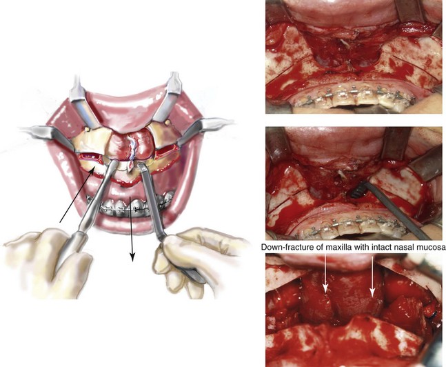
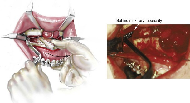
Step 30. Placing the Tessier (blunt) hook behind the maxillary tuberosity and applying anterior and contralateral directed force to one side at a time assists with the disimpaction of the maxilla (Fig. 15-18). The advantage of the Tessier hook is that it assists with the mobilization of the maxilla without contusion of the palatal mucosa, which may occur with standard (Rowe) nasomaxillary disimpaction forceps. When disimpacting with the Tessier hook behind the tuberosity, the surgeon’s other hand is used to grip the anterior maxilla (rather than the teeth) and to apply simultaneous anterior and contralateral force. This is helpful to prevent the fracturing of the tuberosity by the Tessier hook. This is repeated on each side two times to achieve maximum disimpaction. During this process, the assistant to the surgeon stabilizes the patient’s head with one hand over each ear. For a maxillary disimpaction that requires more extensive advancement, the Rowe forceps may be required.
Septoplasty and the Reduction of the Inferior Turbinates ( Video 6:4 and 7:4)
Step 31. When indicated on the basis of the patient’s history and clinical examination, attention is turned to the removal of the deviated portions of the septum of the nose that are causing blockage of the airway.
A With an elevator, the submucosal dissection of the cartilaginous septum (i.e., the quadrangular cartilage) and the bony septum (i.e., the vomer and the perpendicular plate of the ethmoid) is carried out (Fig. 15-19, A).
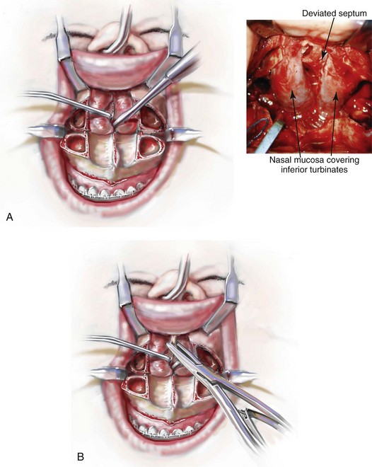
B The deviated and thickened aspects of the cartilaginous septum and the bony septum are resected with a rongeur (Fig. 15-19, B). The more anterior components of the cartilaginous septum that provides needed support to the nasal dorsum and the tip are not disturbed. This includes at least 1 cm of the dorsal and caudal cartilage. When a maxillary intrusion (i.e., for impaction) is planned, even if septoplasty is not required to correct chronic nasal obstruction, the inferior aspect of the septum (i.e., the bone and cartilage) is removed to prevent buckling.
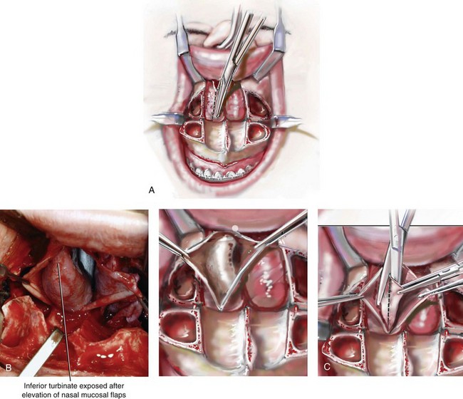
Step 32. When indicated by the patient’s history and physical examination, attention is turned to reducing each hypertrophic inferior turbinate that is causing blockage of the airway. An incision is made through the nasal mucosa just below and parallel to each turbinate (Fig. 15-20, A). If the nasal mucosa was torn during down-fracture, the laceration is used and may be extended for improved turbinate exposure. Each enlarged inferior turbinate is visualized (Fig. 15-20, B), and the inferior aspect of each is resected with a straight Mayo scissors (Fig. 15-20, C). Hemostasis is obtained along the cut edge of each turbinate with the Bovie electrocautery device (Fig. 15-20, D). The nasal mucosa is reapproximated with interrupted sutures (3-0 Vicryl [polyglactin 910]) to create a closure that is as watertight as possible (Fig. 15-20, E).
 NOTE: To prevent a fire in the operative field, if there are any air leaks around the nasotracheal tube, then the electrocautery device is not used.
Removal of the Maxillary Wisdom Teeth ( Video 6:5)
Impacted Wisdom Teeth
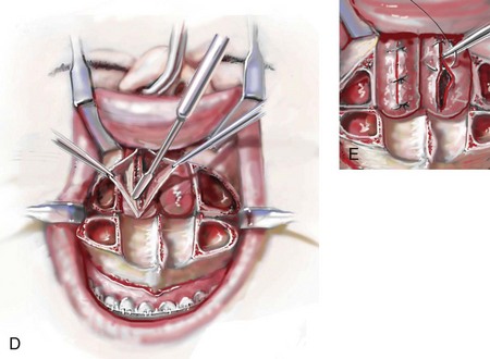
A If indicated, each bony impacted maxillary wisdom tooth is removed through the sinus floor (Fig. 15-21). A rotary drill with a small watermelon bur is used to remove bone from the sinus floor that is directly over the impacted tooth. Next, using a rotary drill with a tapered fissure bur, bone is removed adjacent to the impacted tooth. Depending on the extent of tooth development, the impacted wisdom teeth may also be sectioned to assist with removal. A dental elevator is used to remove the tooth. Perforation through the palatal mucosa is an uncommon occurrence.
Erupted Wisdom Teeth
B If indicated, each erupted maxillary wisdom tooth is removed before down-fracture. This provides a stable “workbench” at the time of extraction. To preserve maximum circulation to the down-fractured maxilla, it is important to minimize the disruption of the adjacent palatal and labial mucosa at the time of extraction.
Segmentation of the Maxilla: Continued
Three Segments
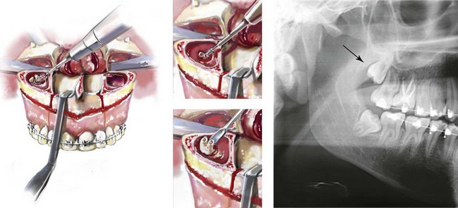
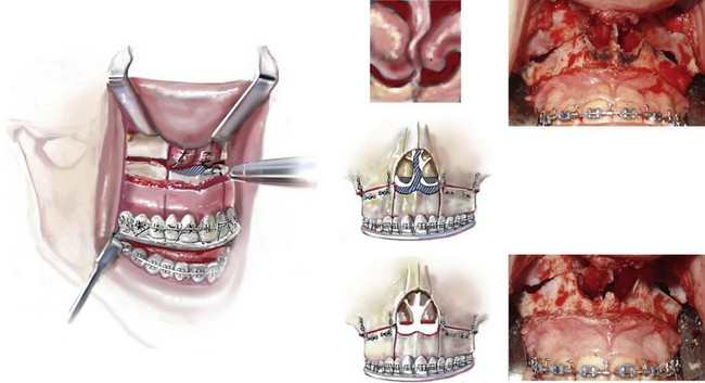
A Description of a three-piece Le Fort I osteotomy with interdental cuts between the lateral incisor and the canine on each side connected to parasagittal osteotomies through the hard palate:
(1) The parasagittal maxillary osteotomy is completed through the down-fracture using a reciprocating saw with a short, straight blade. The osteotomy is from the posterior edge of the hard palate anteriorly to the pre maxillary region (Fig. 15-22, A-1).
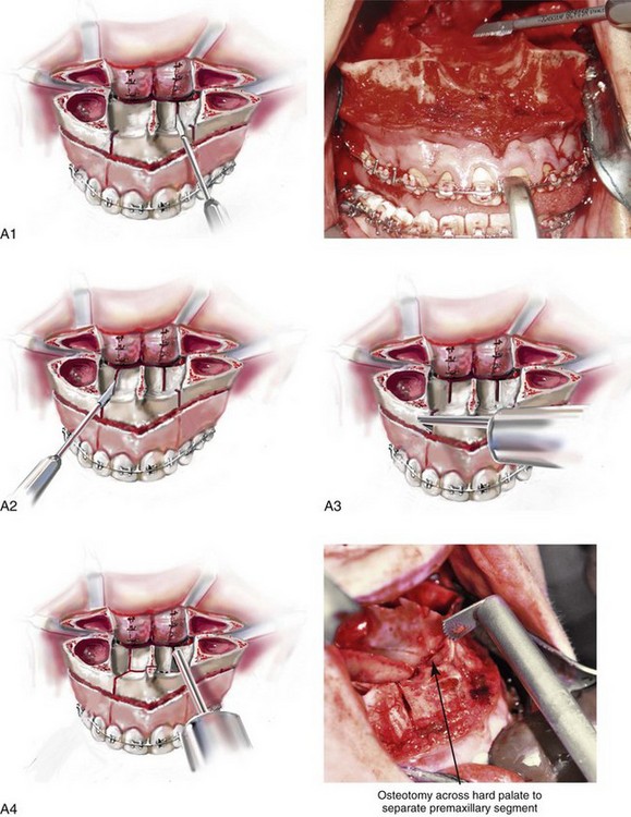
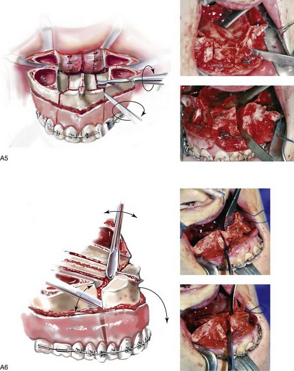
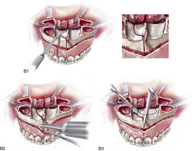
Figure 15-22 A, Step 34, A, Part 1 through Part 4. Step 34, A, part 5, 6. B, Step 34, B, Part 1 through Part 3.
(2) If the planned posterior arch-width expansion is significant, then a second parasagittal osteotomy is also completed on the contralateral side (Fig. 15-22, A-2). The two parallel parasagittal osteotomies allow for a more tension-free expansion than a single osteotomy.
(3) The previously initiated interdental osteotomies are deepened using an oscillating saw with a longer, fan blade on a long shaft (Fig. 15-22, A-3).
(4) The oscillating saw with a longer, fan blade on a long shaft is also used to connect each interdental osteotomy to the parasagittal osteotomy along the floor of the nose at the level of the incisal foramen (Fig. 15-22, A-4).
(5) A fine chisel (i.e., 5 mm or 7 mm in width) is placed into the interdental osteotomy on the same side as the parasagittal osteotomy, and an elevator is placed into the parasagittal palatal osteotomy (Fig. 15-22, A-5). Twisting the elevator and chisel simultaneously assists with the splitting of the maxilla into segments.
(6) The fine chisel (i.e., 5 mm or 7 mm) is then placed into the other interdental osteotomy site, and an elevator is placed in the nasal floor osteotomy site. With a twisting motion, separation is completed (Fig. 15-22, A-6). Perforation through the palatal mucosa (when completing the parasagittal palatal osteotomy) with a reciprocating saw may occur. The creation of a permanent palatonasal fistula or the compromise of the circulation to the maxillary segments should be an uncommon occurrence (see Chapter 16).
Two Segments
B Description of a two-piece Le Fort I osteotomy with an interdental cut between the central incisors connected to parasagittal osteotomies through the hard palate:
(1) The parasagittal palatal osteotomy is completed through the down-fracture using a reciprocating saw with a short, straight blade from the posterior edge of the hard palate anteriorly to the level of the incisive foramen (Fig. 15-22, B-1). If the planned posterior arch-width expansion is significant, then a second parasagittal osteotomy is also completed on the contralateral side.
(2) The previously initiated interdental osteotomy is deepened using an oscillating saw with a longer, fan blade on a long shaft (Fig. 15-22, B-2).
(3) A fine chisel (i.e., 5 mm or 7 mm in width) is placed into the interdental osteotomy, and an elevator is placed into the parasagittal osteotomy. Twisting both simultaneously assists with the splitting of the maxilla into the two segments (Fig. 15-22, B-3). Perforation through the palatal mucosa when completing the parasagittal palatal osteotomy may occur. The creation of a permanent palatonasal fistula or the compromise of the circulation to the maxillary segments should be an uncommon occurrence.
Maxillary Le Fort I Osteotomy: Continued ( Video 6: 6-10 and 7: 5-9)
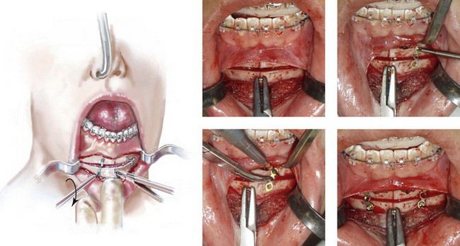
Step 35. The maxillary segments are next secured into the prefabricated acrylic intermediate occlusal splint with the use of 26-gauge wire placed through interdental drill holes in the splint and around the orthodontic arch wire (Fig. 15-23).
Step 36. The maxillary segments are secured to the mandible in the occlusion established by the “intermediate” splint with the use of 26-gauge wire loops passed around hooks located on the orthodontic arch wires (Fig. 15-24).

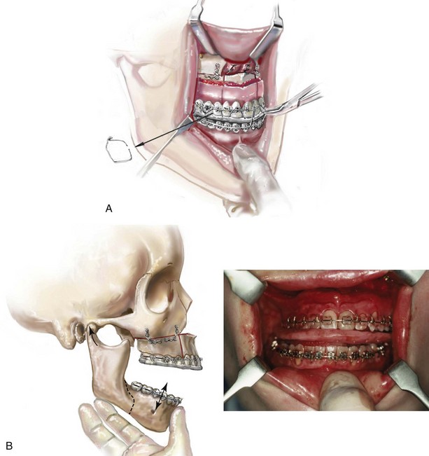
Step 37. With the condyles seated in the terminal hinge position (i.e., the same position that they were in when capturing centric relation in the office setting), the maxillomandibular complex is rotated to achieve the vertical dimension that was preoperatively determined (Fig. 15-25, A).
A If vertical shortening (impaction) of the maxilla is planned, this will require the removal of bone interferences with rongeurs or using a rotary drill with a watermelon bur.
B The Tessier caliper is used to measure the anterior vertical dimension (i.e., the anterior facial height) of the midface (i.e., the medial canthus to the mid-maxillary incisor on each side) to confirm that the desired vertical height is achieved (Fig. 15-25, B).
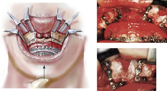
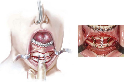
Step 38. With the condyles remaining in the terminal hinge position (i.e., the same position that they were in when capturing centric relation in the office setting) and with the maxilla in the preferred vertical location, appropriately sized and individually contoured L-shaped titanium plates (one by one) are most frequently placed across each zygomatic buttress and at each lateral nasal rim and secured with titanium screws (1.7 mm in diameter and 4 mm in length) (Fig. 15-26).
A The jaws are unwired (Fig. 15-27, A).
B With the condyles seated in the terminal hinge position, the mandible is rotated vertically (up and down) to check the occlusion. The occlusion must be found to be even within the intermediate splint (Fig. 15-27, B).
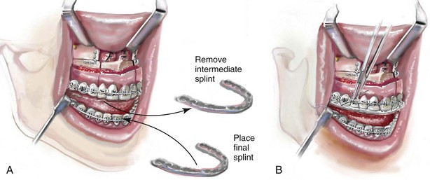
A After the occlusion is determined to be even, the intermediate splint is removed.
B The “final” splint is placed on the maxillary teeth and secured to the orthodontic wire (Fig. 15-28, A). This is accomplished with the use of 26-gauge wires passed through the interdental drill holes in the “final” splint and around the orthodontic arch wire (Fig. 15-28, B).
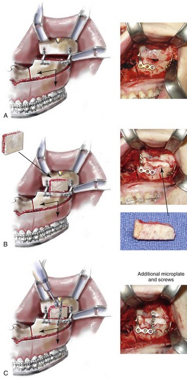
Step 41. When the extent of horizontal advancement and vertical lengthening of the maxilla are judged to be significant, then an interpositional bone graft may be beneficial for the achievement of reliable healing (Fig. 15-29, A). In these circumstances, I prefer to use autogenous or allogenic iliac bone graft. A bloc of corticocancellous bone is crafted and tightly wedged into the gap on each side. Each graft is inset in between the pyriform rim and the zygomatic buttress titanium plates (Fig. 15-29, B). An additional plate is then contoured to extend from the anterior maxilla above, across the graft, and then onto the alveolar process of the anterior maxilla. Titanium screws (1.2 mm in diameter and 3 mm in length). then secure the plate to the bone (Fig. 15-29, C).
Pyriform Rim, Nasal Floor, and Anterior Nasal Spine Recontouring ( Video 6:9 and 7:7)
Step 42. The nasal aperture, the floor of the nose, and the anterior nasal spine are inspected. Refinement and recontouring of these structures using a rotary drill with a watermelon bur are frequently beneficial (Fig. 15-30). For example, in the patient with vertical maxillary excess (i.e., long face growth pattern), the deepening and recontouring of the nasal floor, the pyriform rims, and the anterior nasal spine will generally improve nasal airflow (i.e., the correction of a tight nasal inlet and an elevated nasal floor) and also enhance nasal aesthetics (i.e., limit unwanted alar base widening and tip elevation).
Chin Osteotomy ( Video 6:11 and 7:10)
Step 43. Attention is next turned to the facial vestibule of the chin. The lower lip is stretched outward to allow for exposure of the vestibule and the visualization of the mental nerve through the mucosa on each side. In the depth of the vestibule, an incision is made with the use of a Bovie electrocautery device or a knife (#15 blade) through the mucosa from cuspid region to cuspid region, stopping just short of the visualized mental nerve on each side (Fig. 15-31). The center two thirds of the incision are next extended down to bone. A full cuff of mucosa and muscle is maintained adjacent to the attached gingiva of the anterior teeth. This should allow for adequate layered wound closure (i.e., involving muscle and mucosa) without resulting periodontal sequelae.
Step 44. Dissection with an elevator exposes the anterior surface of the chin (not completely to the inferior border of the central chin). The dissection continues laterally and remains inferior to the mental nerve, with lateral exposure to the inferior border of the mandible. There is no need to dissect above the mental nerve on either side. If a 360-degree dissection around the nerve is completed, it is more likely that the nerve will be excessively stretched or avulsed.
Step 45. A small S-shaped Tessier chin retractor is placed on each side inferior to the mental nerve and laterally to the inferior border. A sterile pencil is used to mark the location of the oblique osteotomy (Fig. 15-32); this should be planned sufficiently below the dental roots and the mental foramen on each side. The exact location of the osteotomy will depend on the presenting chin morphology and the planned reconstruction (i.e., vertical reduction or lengthening and extent of horizontal advancement).
Step 46. Using an oscillating saw with a short fan blade on a long shaft, a vertical groove is made in the midline across and perpendicular to the proposed horizontal osteotomy (Fig. 15-33, A). This will help to maintain vertical orientation after the osteotomy and before fixation.
Step 47. A drill hole is placed in the midline within the distal chin (Fig. 15-33, B). Later, a screw (1.7 mm in diameter and 8 mm in length) will be partially inserted. The screw is not placed in the distal chin until the osteotomy is completed. It will then be held with a wire twister and used as a retractor and a holder to facilitate the repositioning and orientation of the distal chin unit.
Step 48. The oblique osteotomy of the chin is initiated in the central portion using an oscillating saw with a wide, fan blade on a short shaft (Fig. 15-34). The use of this saw and blade helps to maintain orientation and limit a cant in the osteotomy.
Step 49. The reciprocating saw with a short blade and then with a longer blade is used to complete the lateral aspects of the osteotomy and to go through the depth of bone on each side (Fig. 15-35). An osteotome may be inserted with a twisting motion to complete the osteotomy separation.
Step 50. When vertical shortening of the chin is planned, there are two options.
A If only limited shortening is required in combination with horizontal advancement, it may be preferable to use a rotary drill with a watermelon bur to remove bone height at the osteotomy line.
B If a more significant vertical reduction is planned, a second parallel osteotomy for ostectomy is completed through the proximal chin (below the dental roots) using a reciprocating saw with a long straight blade. Any lateral irregularities are also removed using a rotary drill with a watermelon bur. This is to limit postoperative palpable or visible step-offs.
Step 51. The distal chin is held in the desired position by the assistant with the use of the wire twister secured to the positioning screw. The surgeon custom contours each titanium plate across the osteotomy site and then secures each plate with screws (1.7 mm in diameter and 4 mm in length). Typically, either a three- or four-hole straight plate is contoured with the ends placed on either side of the osteotomy. The superior screw is usually placed in between the lateral incisor and the canine on each side. With the chin secured in its new location, the positioning screw is removed (Fig. 15-36, A and B).
Step 52. If significant vertical lengthening is carried out, an interpositional graft (i.e., autograft, allograft, or block hydroxyapatite) is crafted and placed in the gap (Fig. 15-37). The graft fills the central gap in between the fixation plates. I do not find it necessary to place graft in the lateral aspect of the gaps. An additional plate with screws is generally placed vertically in the midline across the osteotomy site directly over the graft (see Chapter 18).
Sagittal Split Ramus Osteotomies: Continued ( Video 6:12 and 7:11)
Step 53. Attention is returned to one side of the ramus of the mandible. The previously placed packs are removed and retractors (i.e., tongue, inferior border at buccal extension, toed-in Langenbeck at anterior ramus to retract the cheek, and medium malleable to expose the medial cut) are placed for sufficient exposure to complete the sagittal splitting of the ramus of the mandible.
Step 54. Initially, fine osteotomes (i.e., 5 mm and 7 mm in width) are used with a mallet to confirm that all cortical cuts are complete (Fig. 15-38). When twisting the chisels, a degree of movement should be visualized along the vertical cut down to the inferior border. Care is taken to avoid injury to the inferior alveolar nerve, which is located superficial to the cortex along the inferior aspect of the buccal shelf extension.
Step 55. A larger osteotome (10 mm in width) is then placed deep into the medullary cavity near the second molar of the mandible. A sagittal split spreader forceps is placed deep into the medullary cavity (i.e., more distal) in the buccal extension region (Fig. 15-39). After both of these are in place, a simultaneous twisting and spreading motion is employed to complete the separation. During separation, the neurovascular bundle is visualized, and the correct separation of the condyle (retained to the proximal segment) is confirmed.
Step 56. With the split complete, further freeing of the neurovascular bundle from the proximal segment is sometimes desirable. A thin periosteal elevator may be used to gently tease the neurovascular bundle free from the proximal segment. A rotary drill with a watermelon bur may also be used to release the neurovascular bundle from the proximal segment.
 NOTE: It is not usually necessary to completely free the nerve from the proximal segment. Caution is warranted, because a degree of contusion to the neurovascular bundle will occur when doing so.
Step 57. A curved Kocher clamp is placed on the distal aspect of the proximal segment. The clamp is used as a handle to apply force and to ensure the complete separation and freedom of motion of the proximal and distal segments (i.e., soft-tissue release).
Step 58. The identical sagittal splitting of the ramus of the mandible is completed on the contralateral side; see Steps 51 through 57.
Removal of Impacted Mandibular Wisdom Teeth ( Video 6:12)
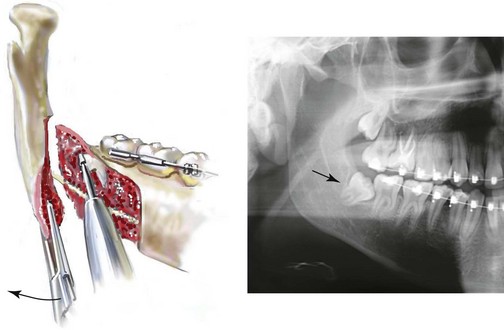
Step 59. If present, each bony impacted mandibular wisdom tooth located within the distal segment is removed with a dental elevator (Fig. 15-40). It may be helpful to use a rotary drill with a tapered fissure bur to remove bone adjacent to the tooth. Sectioning the tooth may be required to facilitate the atraumatic removal of the tooth. This will minimize the chance for an uncontrolled fracture of the lingual plate.
Sagittal Split Ramus Osteotomies: Continued ( Video 6: 12-15 and 7: 11-14)
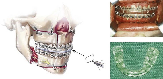
Step 60. The distal mandible is placed into occlusion through the prefabricated final splint, which has already been secured to the maxilla. The jaws are wired together with 26-gauge wire loops placed around the orthodontic interdental hooks (Fig. 15-41).
Step 61. Attention is turned to the proximal segment of the mandible on one side. The proximal segment is seated with the condyle in the terminal hinge position. This is accomplished with the placement of a fine curved hemostat to the edge of the buccal extension. The condyle will then rest in a superior and anterior position within the glenoid fossa (i.e., the same position that it was in when capturing centric relation in the office setting). Any interferences that prevent sufficient passive bone contact of the proximal and distal segments along the osteotomy site are managed using a rotary drill with a watermelon bur (Fig. 15-42). If the mandible is set back, an appropriate section of bone is also removed from the distal aspect of the proximal segment (i.e., the buccal shelf) to prevent any cortex overlap. When setting the mandible back, the removal of bone interferences from the lingual plate of the distal segment is also generally required. These tasks are accomplished using either a rotary drill with a watermelon bur or a reciprocating saw with a short, straight blade.
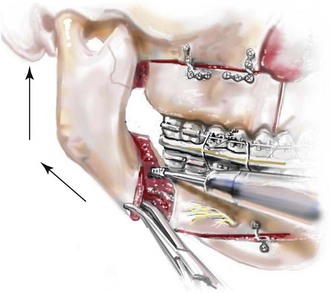
 NOTE: The hemostat is not used to clamp the proximal and distal segments together. Gentle superior and posterior force is applied to seat the condyle in the terminal hinge position.
Step 62. A 4-mm lateral neck incision (just below inferior border of the mandible) is made through the skin for trocar insertion (Fig. 15-43, A through C). The location of the incision is based on the best position of the trocar for ideal bicortical screw placement. With the use of a straight hemostat, blunt dissection through the skin incision is accomplished to achieve intraoral exposure. The trocar is then introduced, and the cheek retractor component of the trochar is placed to improve visualization.
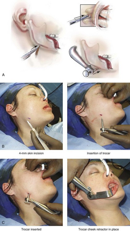
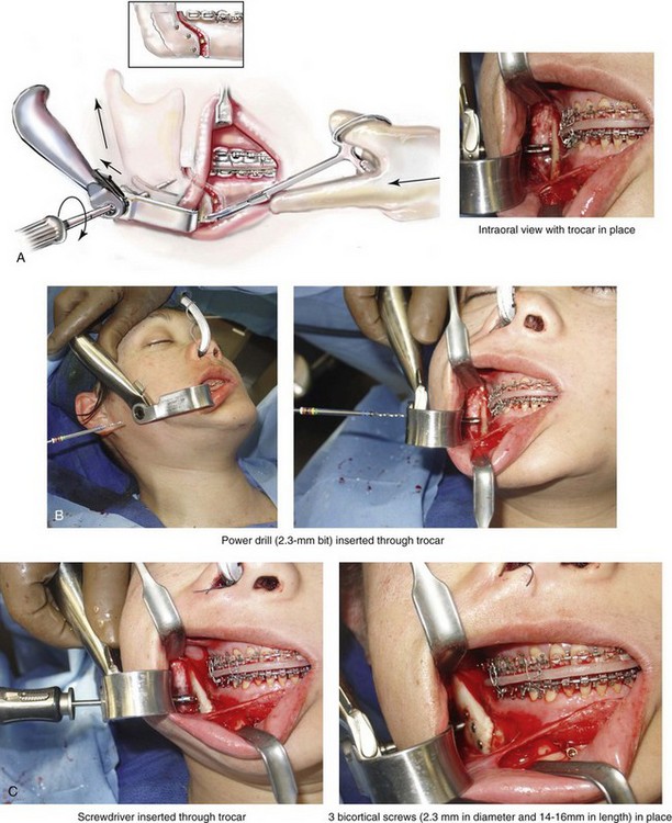
Step 63. The proximal segment is seated with the condyle in the terminal hinge position. This is accomplished via the placement of a fine curved hemostat to the edge of the buccal extension. (Note that the hemostat is not used to clamp the proximal and distal segments together.) Gentle superior and posterior force is applied to seat the condyle in the terminal hinge position. The condyle will then rest in a superior and anterior position within the glenoid fossa (i.e., the same position that it was in when capturing centric relation in the office setting). Three bicortical titanium screws (2.3 mm in diameter and 14 mm to 16 mm in length) are generally sufficient to passively secure the proximal and distal segments together (Fig. 15-44, A through C). The bicortical screws are placed in locations where bone contact is the best. A fourth screw is sometimes placed. Stability is further improved when the screws are positioned as far from each other as possible. Plates with unicortical screws are occasionally preferred to bicortical screw fixation.
Step 64. Attention is turned to the contralateral side, and identical procedures are carried out; see Steps 60 through 63.
Step 65. The jaws are then unwired. With the application of posterior and superior vectored force to the anterior mandible, the condyles are seated in the terminal hinge position. The mandible is then rotated (up and down) to check that the occlusion is even and passive into the splint (Fig. 15-45). If not, the bicortical fixation screws are removed, and the process is repeated; see Steps 59 through 63.
Wound Closure ( Video 6: 16 and 7: 15)
Step 66. The maxillary, mandibular, and chin vestibular wounds are irrigated, suctioned, and checked for hemostasis. The wounds are then closed with interrupted suture (3-0 Vicryl and 3-0 chromic).
A The mandibular vestibular wounds are generally closed in one layer with interrupted suture (3-0 Vicryl). Running and locking (3-0 chromic) suture may be substituted (Fig. 15-46, A). A watertight closure is important to prevent dehiscence followed by increased risk of infection.
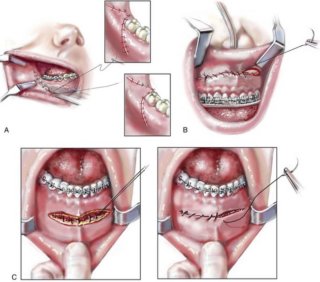
B The maxillary wound is generally closed with running and locking suture (3-0 chromic) (Fig. 15-46, B). The risk of dehiscence or infection is low.
C The wound of the chin is closed in two layers (i.e., muscle and mucosa). Three to five interrupted buried sutures (3-0 Vicryl) are placed for muscle layer closure. Locking and running sutures (3-0 chromic) are used for the closure of the mucosa layer (Fig. 15-46, C). A two-layer closure is essential to limit dehiscence and to prevent chin ptosis.
D The trocar (skin) wounds are closed with two interrupted sutures (6-0 nylon).
Step 67. The mouth is irrigated and suctioned, and the throat pack is removed. An orogastric tube is placed to drain the stomach and then removed. Interdental elastics are applied to secure the occlusion.
Anterior Neck Soft-Tissue Procedures ( Video 7:16)
Step 68. If anterior neck soft-tissue management is planned, it is carried out at this stage. This may include cervical flap elevation, supra-platysma and sub-platysma defatting, and vertical platysma muscle plication (see Chapter 40). Additional prepping with povidone–iodine (Betadine) solution is carried out, and a sterile drape is placed over the standard drapes that are already in place. Sterile instruments and a fresh gown and gloves are used. Injection with tumescent solution is completed in the supra-platysma plane.
A A 3-cm submental incision is made within or just caudal to a natural submental crease.
B Two double skin hooks are placed (i.e., one on either side of the incision) to provide tension on the flaps.
C If the separation of the cervical skin from the underlying platysma muscle is planned, it is accomplished with a blunt-tipped scissors. The cervical skin flap elevation off of the platysma muscle may continue laterally over the sternocleidomastoid muscles inferiorly to the thyroid cartilage and superiorly to the inferior border of the mandible.
D A cannula (no. #7 plastic curved) is used to suction the fat above and in between the platysma muscles.
E Plication of the platysma muscle in the midline (vertically) from above the thyroid cartilage to just below the chin may also be carried out with interrupted suture ties (3-0 Vicryl).
F After confirming satisfactory hemostasis, the submental skin wound is closed in two layers: dermal (5-0 Vicryl) and skin (6-0 nylon).
G A light pressure dressing (Jobst type) is generally applied to the neck. In general, I do not find it necessary or useful to place a drain.
Emergence from Anesthesia
Step 69. The corneal shields or temporary tarsorrhaphies, if used, are removed. The sutures used to secure the endotracheal tube to the scalp and the septum of the nose are released. When the appropriate physiologic parameters are met, the patient is generally extubated in the operating room and then taken to the recovery room breathing spontaneously. If any airway need arises, the interarch elastics are removed without concern (see Chapter 11).
References
1. Luhr, HG. Zur stabilen osteosynthese bei unterkiefer–frakturen. Dtsch Zahnarztl Z. 1968; 23:754.
2. Posnick, JC, Fantuzzo, JJ, Troost, T. Simultaneous intranasal procedures to improve chronic obstructive nasal breathing in patients undergoing maxillary (Le Fort I) osteotomy. J Oral Maxillofac Surg. 2007; 65:2273–2281.
3. Posnick, JC. Le Fort I, sagittal split and genioplasty: historical perspective and step-by-step approach. In: Posnick JC, ed. Craniofacial and maxillofacial surgery in children and young adults. Philadelphia: W. B. Saunders Company; 2000:1081–1102.
4. Obwegeser, HL. In Trauner R, Obwegeser H, editors: Zur operationstechnik bei der progenie und anderen unterkieferanomalien. Dtsch Zahn- Mund- u Kieferheilk. 1955; 23:1–26.
5. Obwegeser, HL. The surgical correction of mandibular prognathism and retrognathia with consideration of genioplasty. I. Surgical procedures to correct mandibular prognathism and reshaping of the chin. Oral Surg Oral Med Oral Pathol. 1957; 10:677–689.
6. Obwegeser, HL. Der offene biss in chirurgischer sicht. Schweiz Monatschr Zahnhlkd. 1964; 74:668–687.