Refraction and prescribing
4.1 Differential diagnosis information from other assessments
4.3 Interpupillary distance (PD)
4.6 Monocular subjective refraction
4.7 Best vision sphere (maximum plus to maximum VA; MPMVA)
4.8 Best vision sphere (the plus/minus technique)
4.9 Duochrome (or bichromatic) test
4.10 Assessment of astigmatism
4.1 Differential diagnosis information from other assessments
4.1.2 The patient’s ocular history
The natural progression of the type of ametropia given the patient’s age can indicate what change in refractive correction to suspect. For example, a childhood-onset myope who obtained their first spectacles at age 12 and is now 16 is likely to attend an examination complaining of increased myopia given the typical progression of myopia. Any mention of cataracts in the case history should lead to a careful investigation for increased myopia (nuclear cataract) or astigmatic change (cortical cataract).1
4.1.3 Family ocular history
When examining children who do not wear spectacles, it is useful to ask whether any of the patient’s family wear glasses or contact lenses. Mutti and colleagues reported that juvenile onset myopia was evident in 33% of the offspring of two myopic parents, compared with only 6% of the children of two non-myopic parents.2 A family history of hyperopia highlights possible amblyopia.
4.1.4 General health
Diabetes, either undiagnosed or poorly controlled, can lead to wide fluctuations in refractive error, with either hyperopic or myopic shifts. In addition, a variety of systemic medications can lead to refractive error shifts.3
4.1.5 Distance vision and habitual VA
For low myopic refractive errors and hyperopic changes in absolute presbyopes, a degradation of one line of vision (on a logMAR chart) corresponds to approximately −0.25 D of refractive error (although very approximate and dependent on pupil size and patient blur tolerance).4 For example:
1. Vision of 20/40 (6/12) in a young adult patient suggests a four-line loss in VA and an equivalent spherical correction of approximately −1.00 DS.
2. Astigmatism in adults changes with age from with-the-rule in young adults to against-the-rule in older patients.5 However, these changes in astigmatism are often minimal over the typical 1–3 year period between eye examinations, so that habitual distance VA reductions in spectacle wearing myopic astigmats and older hyperopic astigmats tend to indicate the change in spherical power required. Therefore, a myope of −1.00/−0.50 × 180 with a habitual VA of 6/12 or 20/40 is likely to need a change in refractive correction of -1.00 DS and an updated prescription to approximately −2.00/−0.50 × 180.
4.2 Focimetry
These devices are also referred to by trade names in some countries, including lensometer or lensmeter (America) and vertometer (Australia). Automatic focimeters are available that measure the lens characteristics mentioned above once the lens has been appropriately positioned and provide a printout of the results. These are very simple to use and the measurement procedure will not be explained. Their main disadvantage is that they break down more often than non-automated focimeters.6
4.2.2 Procedure
 See online video 4.1.
1. Explain the test to the patient: ‘I am going to measure the power of your spectacles.’
2. Set the power of the focimeter to zero and focus the eyepiece (turn it as far anti-clockwise as possible, then slowly turn it clockwise until the target and graticule first come into sharp focus).
3. Measure the back vertex power (BVP) by placing the spectacles on the focimeter with the back (ocular) surface away from you. Position the middle of the right lens against the lens stop.
4. Look into the focimeter and adjust the lens position vertically (using the lens table) and horizontally until the illuminated target is placed in the middle of the reticule. If the lens is high powered, you may need to turn the power wheel to bring the target into focus before it can be centred.
5. Fix the lens into position using the lens retainer.
6. To obtain the power of the sphere, turn the power wheel to bring the target into focus.
(a) If the entire target is focused at the same time (Figure 4.1), the lens is a sphere and there is no cylindrical component. Record the sphere power for the right eye from the power wheel or the internal scale and go to step 8.
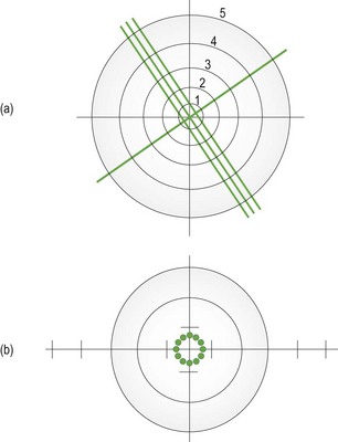
Fig. 4.1 The entire focimeter target is in focus at the same time, indicating a spherical lens. The graticule scale allows measurement of prism. (a) A focimeter that uses a cylindrical (3-line) and spherical (1-line) target. The graticule scale is numbered 1 to 5. (b) A focimeter that uses a circle of dots target. The graticule scale is indicated by the intersecting lines and runs from 1–5 horizontally and 1–3 vertically in both directions from the centre. With an astigmatic lens, the dots become lines orientated along the two principal meridians.
(b) If parts of the target are in focus at different powers and to record in the standard negative cylinder format, turn the power wheel until the meridian with the most plus power (or least minus power) is brought into focus.
(c) With focimeters using line targets, rotate the axis wheel until the sphere line (Figure 4.1a) is in focus and the line is continuous without breaks. You may need to use the power wheel to gain best focus.
(d) Record the sphere power from the power wheel or internal scale.
7. To obtain the power and axis of the cylinder:
(a) Focus the image in the meridian at 90° from the first meridian by turning the power wheel towards the most minus (or least plus) power.
(b) Read off the power when this meridian is in focus. With focimeters using line targets, the cylinder lines will be in focus.
(c) Record the difference between the sphere power from step 6d and the new meridian power as the cylinder power.
(d) Record the orientation of the second meridian from the eyepiece protractor or the axis wheel as the cylinder axis. With focimeters using line targets, this will be the orientation of the cylinder lines (Figure 4.1a).
8. Make sure the target is centred in the graticule and dot the right lens using the focimeter’s marking device. This could be just one spot (the lens optical centre) or three dots (the middle is the lens optical centre, the other two indicate the horizontal line).
9. Release the lens retainer and repeat steps 5 to 8 for the left eye. Do not change the vertical position of the lenses between measurements of the right and left lenses as you need to determine if any vertical prism is incorporated in the spectacles.
10. Move the lens horizontally until the target is in the same vertical plane as the centre of the graticule and dot the left lens using the focimeter’s marking device.
11. If the target is above or below the centre of the graticule, vertical prism is present and should be recorded to the nearest 0.5Δ using the graticule scale (Figure 4.1).
12. Remove the spectacles from the focimeter and measure the distance between the right and left optical centres to calculate the distance between centres (DBC). Record the DBC in mm.
13. For front-surface solid multifocal lenses, the reading add must be measured using front vertex power (FVP). Turn the lens around so that the ocular surface faces you and reposition the spectacles in the focimeter. Measure the FVP along one meridian in the distance portion of the spectacles. Measure the FVP along the same meridian in the near portion of the spectacles. The difference between these powers is the reading addition. Repeat the measurement in the left lens. For low-powered lenses, the FVP approximately equals the BVP, and the BVP add can be measured.
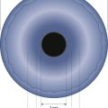
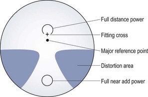
14. For progressive addition lenses (PALs), the appropriate position on each lens to measure the distance and near prescription, optical centres and any prism must first be found (Figure 4.2). A faint mark is etched into both the nasal and temporal sides of each lens, and this must be found and marked with a non-permanent marker. The mark may also indicate the PAL manufacturer and the power of the addition. Use the manufacturer’s marking up card, to find the appropriate distance and near centres and measure the sphero-cylindrical power as previously described. Use the card to determine where to mark the optical centres and where to check for any prism (Figure 4.2).
15. Compare the distance DBC and the patient’s interpupillary distance (PD). If these distances are different, calculate the induced horizontal prism using Prentice’s rule (induced prism = Fc, where F is the power of the lens along the horizontal meridian and c is the difference between the DBC and PD in cm). The direction of the prism also needs to be deduced.
4.2.4 Interpretation
One of the most common errors in focimetry is an axis reading incorrect by 90°.6 Given that the cylindrical axes in the two eyes are often mirror images of each other (for example, both axes 90° or both axes 180°; right axis 175°, left 5°; right 20°, left 160°; right 45°, left 135° etc.), if axes are 90° different to this (for example, 180° and 90°; 175° and 95°; 20° and 50°; both axes 45°; both axes 135°) then recheck the two cylindrical axes.5,7 Reading additions are typically the same in both eyes, so that if they are read as different, they should be rechecked.
4.2.5 Most common errors
(a) Reading one or both of the cylindrical axes incorrectly by 90°.6
(b) Not focusing the focimeter eyepiece. This can lead to inaccuracies for high-powered lenses.
(c) Not measuring the reading addition using FVP measurements for front-surface solid multifocals.
(d) Ignoring the relative vertical position of the target between the right and left lens, thereby missing vertical prism.
(e) Changing the vertical position of the lenses between measurements of the right and left lenses, thereby incorrectly reading vertical prism.
4.3 Interpupillary distance (PD)
(a) To place the optical centre of the phoropter/trial frame lenses in front of the patient’s visual axes to control prism and avoid aberrations.
(b) So that the optical centre of spectacle lenses can be placed in front of the patient’s visual axis to avoid unwanted prism and aberrations or deliberately placed elsewhere to produce desired prism.
4.3.1 Anatomical PD
Anatomical PD measurement is quick and convenient to use during an eye examination and it requires no instrumentation other than a simple millimetre ruler. The repeatability of anatomical binocular PD measurements is similar to that for a pupillometer.8,9 A pupillometer could be considered when refracting or dispensing a patient with a large amount of ametropia, where slight discrepancies in PD could lead to induced prism, and for monocular measurements when dispensing progressive addition lenses.
4.3.2 Procedure
2. Explain the test to the patient: ‘I am going to measure the distance between your eyes so that I can put your lenses in the correct position for your eyes.’
3. Face the patient directly at the distance desired for the near PD (usually about 40 cm).
4. Rest the PD ruler on the bridge of the patient’s nose or on the forehead so that the millimetre scale is within the spectacle plane. Steady your hand with your fingers on the patient’s temple to ensure that the ruler is held firmly in place.
Distance PD
5. Close your right eye and ask the patient to look at your left eye. (It is usually easiest to indicate with your finger the eye that you want the patient to fixate.) To allow a patient with unilateral strabismus to fixate, you may need to cover the fellow eye.
6. Choose a point of reference on the patient’s right eye. The temporal pupil margin is usually most convenient, although the centre of the pupil or the temporal limbus margin may also be used and the latter may be essential with patients with dark irides. Align the zero point on the ruler with this reference point.
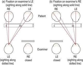
7. Close your left eye, open your right and ask the patient to change fixation to your open right eye. Take care not to move the ruler or your head position. By sighting again to the appropriate reference point on the patient’s left eye, you will obtain a reading for the distance PD (Figure 4.3). This would be the left nasal pupil margin if you used the temporal pupil margin of the right eye.
Near PD
8. Move laterally to place your dominant eye opposite the patient’s nose.
9. Ensure that you are still at a distance from the patient equal to their near working distance. Normally this is done at 40 cm but, if desired, the near PD can be measured for a closer or farther working distance.
10. Using your dominant eye only, choose a point of reference on the patient’s right eye and align the zero point on the ruler with this reference point.
11. Look over to the patient’s left eye and note the reading on the ruler that aligns with the corresponding reference point on the left eye (Figure 4.3a).
4.3.3 Recording
The values are normally recorded as distance PD/near PD (in mm). For example, PD: 63/60.
4.3.4 Interpretation
For women the distance PD is most commonly in the range of 55 to 65 mm, and for men, 60 to 70 mm.10 Young children may have PDs as low as 45 mm. The distance PD value is usually 3 or 4 mm greater than the near PD at 40 cm.10 Inaccuracies in anatomical PD can occur due to parallax error when there is a large difference between your PD and patient’s PD. However, the error is slight, with an 8 mm difference in the examiner and patient’s PDs leading to a 0.5 mm error in the measured patient PD.11 The repeatability of anatomical PDs taken by an experienced practitioner is approximately ± 1–2 mm.8,9 Repeatability between practitioners is slightly poorer at about ±1.5–2 mm.9
4.3.5 Most common errors
1. Moving the ruler during the measurement. Make sure it is held firmly and steadily in position. After taking the distance PD reading, it is a good idea to re-open your left eye, have the patient switch fixation back to it and check that the zero mark on the ruler is still aligned with the original reference point on the patient’s right eye.
2. Using an inaccurate near test distance. Most commonly, unwittingly drifting in closer than 40 cm so the near PD turns out to be lower than it should be. The test distance should not affect the distance PD measurement.
3. Using a PD ruler that is not accurately calibrated, such as some give-away rulers provided by optical companies.
4.3.6 Alternative procedure: Corneal reflection pupillometer
Pupillometers allow monocular PDs to be measured more accurately than an anatomical measurement.9 This is beneficial when ordering spectacles for high refractive errors or for progressive addition lenses where precise centration of each lens along the patient’s visual axes is necessary. In addition, the procedure is quick and simple and could be performed by a clinical assistant and the examiner does not need to be binocular. The PD measured with a corneal reflection pupillometer will typically be 0.5–1 mm smaller than the anatomical PD.8,9 This is because pupillometers measure the ‘physiological PD’, the distance between the two principle corneal reflexes, and locate the visual axes, whereas the anatomical PD locates the lines of sight or optical axes. Note that many pupillometers use a correction for the parallax error mentioned in the anatomical PD section.11 Inaccuracies can occur if the pupillometer sits higher or (usually) lower on the bridge than the intended spectacle frame and the nose is not straight, so that the monocular PDs can be shifted to one side.
4.4 Phoropter or trial frame?
4.4.1 Advantages of a phoropter

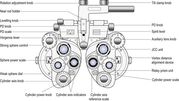
The use of a phoropter (Figure 4.4) is the preferred technique for distance vision refraction of the majority of patients. The main advantages of phoropters are:
• A quicker refraction: As the lenses are all contained within the phoropter, it is much quicker to change lens powers for both retinoscopy and subjective refraction than with a trial frame. This may also provide less back strain for the examiner.
• Comfort: The trial frame containing several lenses can become uncomfortably heavy, particularly for older patients.
• Jackson cross-cylinder alignment: On all modern phoropters, the Jackson cross-cylinder (JCC) is automatically aligned with the cylinder axis in the phoropter.
• No lens smear: Trial case lenses can become covered with fingerprints, and require regular cleaning. The trial frame should also be regularly cleaned.
• Risley prisms: These are standard on phoropters and make measurements of subjective heterophoria and fusional reserves faster and easier and allow for easy use of the binocular prism dissociated accommodative balance technique.
• Computerisation: Computerised phoropters are available and can include data links to an automated focimeter (lensmeter) and/or autorefractor.
• High-tech: Some patients may prefer high-tech phoropters rather than the ancient-looking trial frame.
4.4.2 Advantages of a trial frame

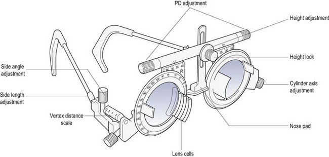
In the routine refraction of presbyopic patients, the trial frame (Figure 4.5) is preferred for the final determination of the near addition, as the test can be performed at the patient’s preferred working distance and position, and the range of clear vision can be easily measured and compared to the near vision requirements of the patient. A trial frame is also useful to illustrate the improvement in distance vision in the ‘real world’ that a pair of spectacles could provide. For example, the new refractive correction can be placed into the trial frame and the patient shown the improvement of their vision while looking through the window of the practice. This can be particularly useful when partially prescribing (section 4.15).
• Patients with binocular vision problems and children: The trial frame can stimulate less proximal accommodation than a phoropter and it provides more repeatable results of oculomotor status.12 In addition, it is possible to perform the cover test with large aperture lenses in a trial frame, but not with a phoropter. Children can also more easily see their parent/guardian.
• Patients with visual impairment: Large dioptric changes in sphere and a high-powered Jackson cross-cylinder (±0.75 or ±1.00 D) are required in the subjective refraction of these patients to enable them to appreciate a difference in vision. These can be used very easily during a trial frame refraction. In addition, the trial frame can provide larger aperture lenses and allow unusual head and eye positions that may be necessary for visually impaired patients using eccentric fixation.
• Patients with hearing problems: The phoropter obscures the patient’s view of the examiner and therefore prevents communication with sign language or simple hand signals.
• When over-refracting patients being fitted with multifocal contact lenses: helps to keep the visual environment, binocularity and pupil size as close to normal as possible (section 5.11).
• Patients who provide poor subjective responses: Some patients, despite normal or near normal visual acuity, provide poor subjective responses and cannot seem to discriminate between the view provided with and without a 0.25 DS lens or a ±0.25 Jackson cross-cylinder (JCC). Using larger dioptric changes in sphere (±0.50 or ±0.75 DS) and a higher-powered JCC (±0.50 or ±0.75) can sometimes elicit better subjective responses, and these changes are more easily made with a trial frame than with a phoropter.
• Patients with high refractive error: The back vertex power (BVP) of a combination of lenses in the trial frame or phoropter is not necessarily the algebraic sum. It depends on the power, thickness, form and position of the lenses used. After refracting a patient with high ametropia in a trial frame, you should measure the BVP using a focimeter. This is not possible with a phoropter. Indeed, for all phoropter lens powers and their combinations, you are placing your trust in the manufacturer. In addition, the pantoscopic angle and vertex distance can be controlled more easily with a trial frame. Any changes in head position could vary these parameters in a phoropter, but do not in a trial frame as it is fitted to the patient’s head.
• Patients with large angle strabismus: Retinoscopy can be done on the line of sight with a trial frame without occluding the fellow eye allowing for a more accurate measure of refractive error and particularly astigmatism.
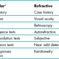
4.5 Objective refraction
4.5.1 Comparison of tests
Retinoscopy provides a more accurate result of refractive error in a greater array of patients than autorefraction, although autorefraction is a useful and reliable alternative in many ‘standard’ adult patients and can be particularly accurate at determining astigmatism.13–15 Autorefractors should not be used with young children without cycloplegia because of proximal accommodation errors producing significantly more minus results than subjective refraction, particularly in young hyperopes.13,16 Retinoscopy also provides a sensitive assessment of the ocular media (e.g. early detection of cataracts, keratoconus), can be used to determine refractive error at distance and near, identify accommodative dysfunction, and is portable, less expensive and less likely to break down.6
4.5.2 Procedure: Retinoscopy (Summary in Box 4.1)

1. Prior to the retinoscopy procedure, it can be useful to estimate the refractive correction from relevant case history and visual acuity information (section 4.1).
2. Set the patient’s distance PD in the phoropter or trial frame, which should be positioned so that it is level with the lenses in the patient’s spectacle plane (~12 mm from the cornea).
(a) Dial in the +1.50 DS retinoscope lens into the phoropter or place working distance lenses in the back cells of the trial frame (+2.00 DS for a 50 cm working distance, +1.50 DS for 67 cm). This technique has the advantage that all ‘with’ movements indicate hyperopia and all ‘against’ movements indicate myopia. It also provides a ‘fogging’ lens to both eyes that will relax accommodation in a low hyperope.
(b) Do not add a working distance lens. The working distance power (+1.50 D or +2.00 D usually) must later be subtracted from your final retinoscope result. This technique has the advantage that you avoid introducing two reflection surfaces from the working distance lens, which can make retinoscopy easier in some cases.
4. Switch on the duochrome (bichromatic), spotlight or a similar distance fixation target that is easy to see when blurred and does not provide a stimulus to accommodation. Computer-based optometry programmes include cartoon and other images for use with children.
5. Explain the test to the patient: ‘I’m going to shine a light in your eye and get an indication of the power of the glasses you may need. Please look at the target, and let me know if my head blocks your view. Don’t worry if the target is blurred.’ Ensure that your head does not block the patient’s view at any time, otherwise they are likely to accommodate to it.
6. Dim the room lights to provide a more high contrast, brighter view of the pupillary reflex, while providing enough light to allow easy viewing of the phoropter/trial case. A totally dark room may induce a dark focus response (Mohindra retinoscopy, see section 4.13.7).
7. Sit or stand off to the side of the patient so that manipulation of the trial frame/phoropter is easy. Use a comfortable working distance from the patient so that you can change lenses in the spectacle plane easily (a comfortable arms, length is often 67 cm or 50 cm). You should be on the patient’s right side and use your right hand and right eye to check the patient’s right eye and vice versa for the left eye.
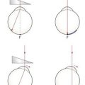
8. Set the retinoscope mirror to the plano position (maximum divergence, with the retinoscope collar at the bottom of its range) and align yourself with the visual axis of the eye you are scoping (their other eye is fixating the distance target; Figure 4.6a), otherwise you will obtain off-axis errors.17
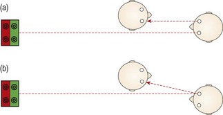
Fig. 4.6 Plan view of the position of the examiner and patient when performing retinoscopy. (a) The examiner is viewing along the visual axis of the patient’s right eye, while the patient’s left eye fixates the duochrome target. (b) The examiner views off-axis in the ‘good’ eye of a patient with strabismus. For the strabismic eye, retinoscopy could be performed along the angle of strabismus, or the good eye could be occluded and retinoscopy performed off-axis.
If the patient is looking slightly upwards to view the target, which is common if it is above the patient’s head and viewed through a mirror, to look along their visual axis you will need to be slightly higher than the patient (Figure 4.7).
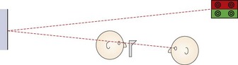
Fig. 4.7 Side view of the position of the patient and examiner when performing retinoscopy when the target is above the patient’s head.
9. Position the streak so that it is vertical. Look through the aperture of the retinoscope and direct the light at the patient’s pupil and you should see the red retinoscope reflex. Sweep the retinoscope streak across the patient’s pupil horizontally and compare the movement of the reflex in the pupil with the movement of the retinoscope. If the reflex moves in the same direction as the movement of the retinoscope streak, this is known as ‘with’ movement. If the reflex moves in the opposite direction to the movement of the retinoscope streak, this is known as ‘against’ movement.
10. Before you begin retinoscopy on a pre-presbyopic patient, you must try to ensure that they will not accommodate while looking at the target. If you are assessing the right eye first, look across to the left eye and if ‘with’ movement is observed, add positive lenses until ‘against’ movement is obtained. This will ensure that the left eye (which is viewing the target) is blurred by at least +1.50 D.
11. Sweep the retinoscope streak across the patient’s right pupil and compare the movement of the reflex in the pupil with the movement of the retinoscope. Mentally note the direction of movement with the streak vertical and also observe the reflex’s brightness, speed and width. Now rotate the retinoscope streak so that it is horizontal and sweep across the pupil vertically and finally observe the reflex movement when the streak is oriented obliquely (45 and 135). For all four streak positions, mentally note the direction of the reflex movement and the relative brightness, speed and width of the reflex movements.
12. Determine if the refractive error is spherical (the observed reflex has the same direction, speed, brightness and thickness in all meridians) or astigmatic (the reflex differs in different meridians). If the reflex movement is relatively slow and any difference between the reflex speed and thickness is difficult to determine, place an appropriate spherical lens in the trial frame to get nearer to neutrality, and check again for astigmatism.
13. If astigmatic, determine the principal meridians by rotating the streak axis until the angle of the reflex movement coincides with the angle of the streak in two meridians; one perpendicular to the other (Figure 4.8).
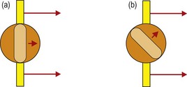
Fig. 4.8 Determining the two astigmatic meridians: (a) If you are scoping on axis, the reflex will move in the same direction as the retinoscopy streak. (b) If you are off axis, the reflex will move in a different direction than the direction of the retinoscopy streak. You should then rotate your streak to align with the reflex.
14. Determine the spherical component by ‘neutralising’ (adding plus lenses to ‘with’ movement and minus lenses to ‘against’ movement until the reflex fills the entire pupil and all perceived movement stops) the most plus/least minus meridian first (the meridian with the slowest, dullest ‘with’ or fastest, brightest ‘against’ movement). Use a bracketing technique to determine neutrality.
15. Check the neutral point by moving forward slightly and observing the movement of the reflex. A ‘with’ movement should be seen. If you move backward slightly from your normal working distance, an ‘against’ movement should be seen.
16. Set the minus cylinder axis parallel with the streak orientation of the least plus/most minus meridian. Move the retinoscope with the streak in this position and you should observe ‘against’ movement. Add minus cylinder in a bracketing technique to achieve neutrality. As ‘with’ movement can be easier to see than ‘against’ movement, you may wish to add minus cylinder until ‘with’ movement is just seen and then reduce the cylinder by 0.25 D.
17. Briefly, recheck the sphere and cylinder components for neutrality. The axis can be checked using Copeland’s ‘straddling’ technique. This involves comparing the speed of rotation and alignment of the reflex at the cylinder axis +45° with that at the cylinder axis −45°. The cylinder axis should be changed until the reflex at these two positions is the same. In spot retinoscopy, the cylinder axis can be checked and refined by sweeping the beam along the axis of the cylindrical trial lens. If the trial cylinder is oriented at the correct axis, the reflex should be in alignment with the spot of light in the trial frame. The axis of the trial cylinder can be adjusted until this is the case. The power of the cylindrical lens should be rechecked following an adjustment of cylinder axis.
18. Repeat steps 11 to 17 on the patient’s left eye.
19. Recheck the right eye. This step may not be necessary if you have ensured that no accommodation has taken place throughout the procedure (see step 10).
20. Remove the +1.50 (or +2.00) working distance lenses (or subtract 1.50 or 2.00 D from your final result).
21. Measure the patient’s visual acuities with the net retinoscopy result.
4.5.3 Adaptations to the standard procedure
1. Improving the accuracy of the cylinder axis estimate
Spherical aberration can provide a more against movement in the periphery of the lens compared to the centre and a common error for inexperienced students is to miss slight ‘with’ movement in the pupil centre for this reason (see online video 4.6) . Concentrate on the central reflex and ignore the reflex at the edges of the pupil.18
During accommodative fluctuations, the pupil will be seen to vary in size and the reflex movement and brightness will rapidly change. This can be seen with young children who change fixation (typically to look at the retinoscope light or their parent/guardian) and the patient needs to be reminded to keep looking at the distance target. If these changes do not appear related to changes in fixation, then accommodative fluctuations that could be due to latent hyperopia or pseudomyopia should be suspected and a cycloplegic refraction (section 4.13) and assessments of accommodation (sections 6.9 to 6.11) should be performed.
Retinoscopy is ideally performed along the patient’s visual axis. In a patient with strabismus, this can be difficult, particularly when using a phoropter. Retinoscopy on the ‘good’ eye must be performed slightly off-axis (Figure 4.6b), and this will lead to errors, so minimise the extent as much as possible.17 For the strabismic eye, it can be easier to change the fixation point for the ‘good’ eye, so that retinoscopy along the visual axis of the strabismic eye is easier.
7. Examiners with poor vision in one eye (e.g. amblyopic examiners)
If you are unable to obtain accurate retinoscopy results in your poorer eye, you can use your better eye on both sides, but you will have to scope off-axis on one side (Figure 4.6b) which will provide incorrect results.17 An alternative is Barrett’s method in which you perform retinoscopy of both the patient’s eyes while the patient fixates the retinoscope and then check the spherical component of this initial result with the patient fixating in the distance using your good eye. For example, if your good eye is the right, scope the patient’s right eye using your right eye. The difference in the spherical correction between distance and near fixation should be applied to the other eye. For example, retinoscopy at near gives: OD: −1.50/−1.00 × 10; OS: −2.00/−0.50 × 170. Retinoscopy in the distance for the right eye gives −2.50/−1.00 × 10, an extra −1.00 DS. Apply this difference to the left eye so that the final retinoscopy result is: OD: −2.50/−1.00 × 10; OS: −3.00/−0.50 × 170.
4.5.4 Adaptations for older patients
Older patients will often have small pupils and some will have media opacities/cataract and you will see a dim reflex as a reduced amount of light reaches the retina and even less returns to your retinoscope. Increasing the retinoscope light intensity may just reduce the pupil size further and a medium intensity is usually best. Often an autorefractor result is not possible for these patients,13 but retinoscopy might provide a useful result if used with these three adaptations:
(i) Perform retinoscopy at a closer distance (sometimes called ‘radical retinoscopy’) such as 25 cm or 33 cm as this can provide a brighter reflex. You will have to subtract a larger value from your retinoscopy result to compensate for the reduced working distance (4.00 or 3.00 D, respectively, for 25 cm or 33 cm). Remember that there is a greater chance of dioptric error when using a close working distance. For example, if you work at 62 cm rather than a correct 67 cm when using a +1.50 DS working distance lens, the error is 0.10 D. The same 5 cm error when assuming a working distance lens of +4.00 D (25 cm) is 1.00 D. There should be no error for astigmatism as long as your working distance remains constant.
(ii) Use the least number of lenses in the trial frame/phoropter. You will lose 8% of the reflex for each lens used due to reflections. Do not use a working distance lens and refract each meridian using a sphere only and convert to a sphere-cylinder combination for the subjective refraction.
(iii) In some retinoscopes you can alter the sight hole size. For small pupils and patients with media opacities you should make sure you are using the large aperture sight hole to see as much light as possible.
4.5.6 Interpretation
On average, retinoscopy provides a refractive result slightly more positive than subjective refraction in young patients.19 This decreases with age, so that retinoscopy and subjective results are similar in presbyopic patients. As the stimulus to accommodation is greater in subjective refraction than in retinoscopy, the retinoscopy result in young hyperopes can be much more positive than accepted in subjective refraction. Errors can occur in retinoscopy if it is performed off-axis (Figure 4.6b), which will induce spherical and astigmatic errors, or if it is performed at an incorrect working distance, which will induce a spherical error.17 The most common working distance error is to work too close, particularly when the reflex is dim. Note that cylinder axes in the two eyes are often mirror images of each other.5,7 For example, right axis 175°, left 5°; right axis 20°, left 160°; right axis 45°, left 135°, etc.
4.5.7 Most common errors
1. Performing retinoscopy at an incorrect working distance, e.g. working at about 50 cm, while using a 1.50 D working distance lens.
2. Performing retinoscopy off-axis.17
3. Using lenses smudged with fingerprints when performing retinoscopy with trial case lenses. This is a bit like performing retinoscopy in patients with cataract. Student trial case lenses are notoriously smudged and you should try to get into the habit of cleaning lenses before using them.
4. Not concentrating on the movement in the centre of the pupil in a patient with large pupils.
5. Blocking the patient’s view of the distance chart, thereby likely stimulating accommodation.
4.6 Monocular subjective refraction
Binocular subjective refraction is the preferred technique for experienced clinicians (section 4.12), but it works most effectively if the starting point is reasonably close to the optimal refractive correction and this cannot be guaranteed with novice retinoscopists. Therefore monocular subjective refraction is the preferred technique when you start to learn subjective refraction.
4.6.1 Procedure

1. Explain the procedure to the patient: ‘During this test, I will place various lenses in front of your eye to find the lenses that give you the best vision. Don’t worry about giving a wrong answer as everything is double checked.’
2. Sit or stand off to the side of the patient so that manipulation of the trial frame/phoropter is easy.
3. Begin with the net retinoscopy sphere-cylinder before each eye. The patient’s distance PD should already be set in the phoropter or trial frame, which should be level and positioned appropriately.
4. The subjective refraction traditionally begins on the right eye. Occlude the left eye.
5. Determine the Best Vision Sphere (section 4.7 for phoropter-based refractions and section 4.8 for trial frame based refractions). This must be performed to ensure that the circle of least confusion is on the retina prior to the use of the Jackson cross-cylinder (JCC).
6. Check that the circle of least confusion is in an appropriate position prior to JCC using the duochrome test (section 4.9).
7. Determine the cylinder axis using the JCC (section 4.10).
8. Determine the cylinder power using the JCC (section 4.10).
9. If you have changed the cylinder power or axis, repeat the Best Vision Sphere assessment (step 5).
11. Repeat steps 5–10 for the other eye.
12. Perform a binocular balance of accommodation (section 4.11).
13. Compare the monocular VAs with your subjective refraction result with the patient’s vision or habitual VAs (as appropriate). If the VA is better with the patient’s spectacles, then it is likely that your subjective result is incorrect. Repeat the subjective refraction (students should perhaps call their supervisor).
14. Compare the VA with the present subjective refraction with age-matched normal data (Table 3.1). If the VA is worse than expected, or worse in one eye compared to the other, remeasure the VA with a pinhole aperture. If the VA improves with the pinhole, either the patient has media opacity, typically cataract that is being bypassed by the pinhole, or the subjective refraction is not optimal and should be repeated. Note that visual acuity will not always improve with cataract, particularly if the opacity is dense and central.
15. If the final refractive correction in either eye is above 5.00 D mean sphere equivalent (MSE, the sphere plus half the cylinder; e.g., −4.75/−1.50 × 180 has a MSE of −5.50 D, +5.50/−2.00 × 90 has a MSE of +4.50 D), then measure the back vertex distance. This is the distance from the back surface of the lens nearest the eye to the apex of the cornea. Back vertex distance can be read from the millimetre scale on the side of the trial frame, from the back vertex distance periscope on the side of the phoropter, or by using a vertex distance gauge.
4.6.2 Recording
Record the refractive correction using the same format described for retinoscopy (section 4.5.5). Record the monocular VAs. If pinhole VA is measured and reveals no improvement in VA, record PHNI (‘pinhole no improvement’); otherwise record the VA with the pinhole. For refractive corrections above 5.00 D equivalent sphere, record the vertex distance. Make sure that the prescription details that you provide to patients are clearly legible. Illegible prescription forms have been reported as a surprisingly common error in optometric practice.6
4.6.3 Interpretation
The subjective results should be compatible with the retinoscopy results in most cases, although young patients may provide a more positive (less minus) correction than retinoscopy.19 Inconsistent results may be due to technique error or the patient may be an unreliable observer for behavioural or visual reasons. A subjective result that is significantly less positive (more negative) than the retinoscopy result or a subjective result more minus than suggested by unaided visual acuity could indicate latent hyperopia or pseudomyopia and a cycloplegic refraction may be required (section 4.13). A patient with reduced VA (typically in both eyes) and a retinoscope result that indicates emmetropia or slight hyperopia may have non-organic visual loss (section 4.12.6). The difference between the patient’s own spectacles and the subjective refraction should be compatible with the difference between the habitual (with own spectacles) and optimal VAs (section 4.12.6).
4.7 Best vision sphere (maximum plus to maximum va; MPMVA)
4.7.1 Procedure
2. Determine the visual acuity of the right eye.
3. Add +1.00 DS to the spherical lens determined in retinoscopy and check the visual acuity. The VA should be reduced by about four lines. If the visual acuity only worsens by one or two lines (or gets better!), add additional positive power to the sphere until four lines of acuity are lost to ensure the eye is ‘fogged’. Experienced practitioners may use a smaller fogging lens such as +0.50 DS.
4. Reduce the amount of fog by 0.25 DS and ask the patient: ‘Are the letters clearer with Lens 1 or 2?’ Check that visual acuity improves with the preferred lens.
5. Continue to reduce the amount of fog in 0.25 DS steps and stop when there is no improvement in visual acuity.
6. Remember that the average acuity of a 20-year-old is about 20/15 (~6/4, –0.14 logMAR; Table 3.1), so that most young patients should be able to read beyond 20/20.
4.7.2 Adaptation for older patients
Processing speed slows significantly with age, so provide a longer presentation time for each lens than you would normally do for younger patients.20 Note that you are more likely to over-plus than over-minus older patients (section 4.7.3).
4.7.3 Interpretation
The MPMVA approach is designed to take advantage of a patient’s depth of focus to provide the maximum range of clear vision.21 For example, after refraction, the retinal image should be conjugate with the distance VA chart at 6 m (20 ft). However, this does not take advantage of the depth of focus. For example, if the depth of focus was +0.50 D and the retinal image was conjugate with the distance VA chart so that 0.25 D of the depth of field was in front of the VA chart and 0.25 D behind it, the chart would be clear from 2.4 m (8 ft) to ‘beyond’ infinity. Using the MPMVA technique places the distal edge of the depth of focus conjugate with the VA chart.21 Therefore, if the depth of focus is +0.50 D, use of the MPMVA technique ensures that the range of clear vision is from 1.5 m to 6 m (5 to 20 ft). However, using this technique does mean that patients are slightly under-minused or over-plussed by 0.16 D as the distance VA chart is at 6 m (20 ft) and not infinity. This can be offset in young patients due to a lead of accommodation (+0.25 DS) during distance refraction, but this does not occur in older patients who have lost accommodation.21 This effect can be aggravated if a truncated VA chart is used (i.e. only reducing plus to obtain a VA ‘bottom line’ of 20/20 or 6/6) and/or if the patient has a large depth of focus (such as older patients with small pupils) as there will be very slight retinal defocus over the entire range except at the precise point of conjugacy.21 Over-plussed/under-minused refractive corrections are more commonly found in older patients than under-plussed/over-minused ones.22 An indication that this has occurred is that the measured addition is lower than expected in the presbyope.
4.7.4 Recording
The results of MPMVA are not recorded as the technique is just part of the subjective refraction.
4.7.5 Most common errors
1. Not monitoring the VA to ensure that a change in lens power results in the expected change in VA.
2. Using a truncated VA chart with a ‘bottom line’ of 20/20 and only unfogging VA to that level. For example if your chart has a bottom line of 20/20, yet the patient can read 20/15, the patient would be slightly over-plussed/under-minused if they were only unfogged to 20/20. Remember that the average acuity of a 20-year-old is 20/15 and some patients can see 20/10 (Table 3.1). Using the JCC when the circle of least confusion is in front of the retina, as it would be in this case, can lead to an incorrect determination of astigmatism.23
4.8 Best vision sphere (the plus/minus technique)

4.8.1 Procedure
1. Occlude one eye. Direct the patient’s attention to the best acuity line.
2. Check that any lenses you are using are clean and free of fingerprints. Student trial case lenses are notoriously smudged and a patient will not be able to see through a dirty lens.
3. Add +0.25 DS and ask: ‘Are the letters clearer, more blurred or the same?’ (+0.50 DS can be used if the initial VA is relatively poor).
4. If the acuity improves or remains the same with the additional plus, then exchange the spherical lens that is in the trial frame for one that has +0.25 DS added. For example, if the patient has −3.00 DS in the trial frame and the letters look clearer with +0.25 DS, then exchange the lens for a −2.75 DS lens.
5. When exchanging plus lenses in a trial frame in a young hyperope, do not remove the plus lens until the new lens has been inserted, otherwise accommodation could be stimulated. For example, if you have +2.00 DS in the trial frame and the patient indicates that additional plus power is required, insert the +2.25 DS lens first, and then remove the +2.00 DS lens.
6. Using the same approach, continue adding plus lens power in +0.25 DS steps, until the acuity first blurs. Stop at the most plus/least minus lens that does not blur the visual acuity.
7. If the visual acuity blurs with a +0.25 DS lens, then do not add it.
8. Direct the patient’s attention to the best acuity line. Add −0.25 DS and ask: ‘Are the letters clearer, more blurred or the same?’ An alternative question when adding −0.25 DS is ‘Does this help you read any more letters?’
9. If visual acuity improves with the lens, then exchange the spherical lens that is in the trial frame for one that has −0.25 DS added.
10. Add further minus lenses (in −0.25 D steps) only as long as the visual acuity improves.
11. If a young patient (i.e., the patient is able to accommodate) reports that vision is improved with the lens, but there is no improvement in visual acuity, ask, ‘Do the letters definitely look clearer, or just smaller and blacker?’ If the letters just look smaller and blacker, do not add the −0.25 DS.
12. If the patient reports no change or a worsening of vision, do not add the −0.25 DS.
13. Duochrome check: Use this as part of best vision sphere determination prior to using the JCC in younger patients (section 4.9).
14. The +1.00 blur check. Use this as part of best vision sphere determination at the end of monocular refraction in younger patients. Place a +1.00 DS trial case lens over the final best vision sphere correction. If the original VA is about 6/4 (the average VA for a young patient, Table 3.1), then VA will blur to about 6/12+ with +1.00 DS.24 If VA is better than 6/12 with the +1.00 DS, then the patient may have been over-minused or under-plussed and the best vision sphere should be rechecked. Note that the four-line loss of VA with the +1.00 blur is an average and VA loss with +1.00 DS can reliably be as small as two lines or as large as 7.24 The vision obtained with the ±0.25 DS is the final arbiter of the best vision sphere and not the +1.00 blur test.
4.8.3 Adaptations for older patients
Older patients, particularly those with reduced VA, may be unable to tell any difference with ±0.25 DS, so that you should use ±0.50 DS or even larger steps. Some older patients also prefer to have two options to choose from rather than three (see 4.8.2).
4.9 Duochrome (or bichromatic) test
The duochrome or bichromatic test is commonly used as a check on the best vision sphere during monocular refraction. It is based on the principle of axial chromatic aberration, where light of shorter wavelength (e.g. green light) is refracted more by the eye’s optics than light of longer wavelength (e.g. red light). Duochrome tests traditionally use a red filter (peak wavelength 620 nm) and a green filter (peak wavelength 535 nm) of equal brightness. The dioptric distance between the foci of these wavelengths is around 0.44 D.23 An eye in a mildly myopic state (e.g. −0.25 DS) will see the target on the red filter more clearly; an eye in a mildly hypermetropic state (e.g. +0.25 DS) will see the target on the green filter more clearly. The test is more rarely used as a binocular balancing technique (section 4.11).
4.9.1 Procedure

1. Some clinicians dim the room lights as this dilates the pupil and slightly increases the chromatic aberration of the eye and provides more reliable responses.25 It also reduces the veiling glare on projected charts.
2. Ask the patient: ‘Are the rings (or letters/dots) clearer and blacker on the red or on the green, or are they are about the same?’
3. If they look the same, check whether the responses are reliable by adding +0.25 DS (the rings on the red should look clearer) and then −0.25 DS (now green). If the responses are appropriate, this suggests that the best vision sphere has been obtained and the circle of least confusion is on the retina.
4. If the rings on the green look clearer, add +0.25 DS until you obtain a balance. Note the additional spherical power required to obtain a balance.
5. If the rings on the red look clearer, add −0.25 DS until you obtain a balance. Note the additional spherical power required to obtain a balance.
6. If more than ±0.50 DS is needed to balance the clarity of the rings (or letters) on the duochrome, this usually indicates that the duochrome test is unreliable for this patient and the results should be ignored.
7. Prior to the use of the Jackson cross-cylinder: If the clarity of the rings changes from ‘green’ to ‘red’ with +0.25 DS or ‘red’ to ‘green’ with −0.25 DS, leave a young patient on the ‘green’ as they will be able to accommodate to bring the circle of least confusion onto the retina.
8. After the use of the Jackson cross-cylinder and prior to finalising the refractive correction: If the clarity of the rings changes from ‘green’ to ‘red’ with +0.25 DS or ‘red’ to ‘green’ with −0.25 DS, note the additional spherical power required to leave a young patient ‘on the red’.
9. Use the additional lens power suggested by the duochrome test and double-check whether this additional power is preferred by the patient using MPMVA (section 4.7) or the plus/minus technique (section 4.8). Note that the duochrome should be used to indicate that you should double-check your result and should not be used as the arbiter of the final refractive correction.
Note: Some practitioners prefer to add +0.50 DS or +0.75 DS to the spherical correction so that the bichromatic test is initially ‘on the red’ and then reduce the plus power (or increase the minus power) in 0.25 DS steps until the targets on the red and green look equally black and clear.
4.9.2 Recording
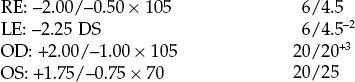
| R: –1.00/–0.50 × 170 L: –1.25/–0.25 × 10 |
R = G 6/4 R = G 6/4 |
| OD: –1.25/–0.75 × 20 OS: –1.75/–1.00 × 165 |
R > G 20/15 R > G 20/15 |
4.9.4 Most common errors
1. Not checking with ±0.25 DS to make sure the patient’s responses are reliable if they initially respond that the rings are equally clear on the red and green.
2. Relying on the result obtained with the duochrome test as the final arbiter of the spherical end point. It is a check test only and may suggest that you repeat part of the best vision sphere assessment.
3. Asking the patient whether the red or green looks brighter (the green will look brighter for a protan and the red for patients with nuclear cataract). You must ask whether the rings (or letters/dots) are clearer and blacker on the red or green.
4.10 Assessment of astigmatism
Most patients have a slight amount of astigmatism. This could be due to astigmatism of the anterior and posterior surfaces of the cornea and/or lens and/or due to lens tilt and/or decentration. Large amounts of astigmatism appears to be hereditary.26
4.10.1 Comparison of tests
There has been little comparison of the various tests to determine astigmatic power and axis in the research literature and the study by Johnson and colleagues provides limited information and further study is needed (section 1.1.2).27 Many practitioners use the Jackson cross-cylinder (JCC) test as it is simple and easy to use and is designed to fine tune the cylinder found in retinoscopy or autorefraction. The method described for fan-shaped tests often assumes that no retinoscopy result is available and even if it is available, the retinoscopy cylinder is removed and you start from scratch. However, it is important to be able to use another subjective test for astigmatism in case a patient responds poorly to the demands of the JCC. Fan-shaped tests have an advantage over JCC in that accommodation is well controlled as the patient is fogged prior to the use of the procedure. They also do not require the patient to be able to memorise two pictures presented sequentially and compare them. They can be used to quickly determine if any astigmatism is present after the best vision sphere procedure by asking patients whether any of the lines look clearer (the block and fan looks like a clown’s face if set up as in Figure 4.9 and can be used with children in this way: Ask ‘Do any of the hairs on the clown’s head look clearer than the others?’). However, fan-shaped tests should only be used if they include an arrow or dial to refine the precision of the axis estimation, otherwise they are significantly limited in sensitivity.28 A very simple test to estimate the astigmatic axis is axis rotation, which involves asking the patient to view the smallest line of VA they can see and rotating the correcting cylinder axis first clockwise and then anti-clockwise until the patient reports that the letters start to blur. The cylinder axis indicated by the technique is the mid-point between the two blur points so that if the two blur points are at 25° and 55°, the indicated cylinder axis is 40°. In patients where the subjective assessment of astigmatism is poor, it is advisable to consider multiple objective measures of astigmatism from retinoscopy, autorefraction, and (to a lesser degree and if the cylinder is not lens-induced) keratometry. The astigmatism present in the patient’s old spectacles should also be considered.
4.10.2 The Jackson cross-cylinder
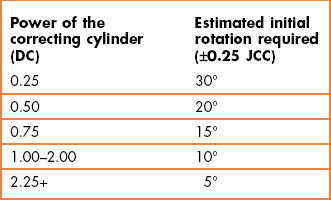
The test only works if the circle of least confusion is on the retina so that it must follow a best vision sphere assessment. During the test you present two lenses to the patient, one after the other: when the correcting cylinder is not correct, one lens should increase the interval of Sturm and slightly blur vision and the other should decrease the interval of Sturm and slightly improve vision. The zero mean power of the cross-cylinder ensures that the circle of least confusion remains on the retina for both presentations. The effective axis shift is greater if the power of the correcting cylinder is low: A ±0.25 JCC will shift the effective axis by ±22.5° when combined with a −0.50 DC, but will only shift the effective axis by about 7° when combined with a 2.00 DC.23 Therefore when making changes based on patient responses to the JCC, the amount of rotation of the correcting cylinder should consider the power of that cylinder (Table 4.1).
4.10.3 Procedure
See online videos 4.9 to 4.14. 
1. Ensure that the best vision sphere is in place so that the circle of least confusion is on the retina: Use the MPMVA (section 4.7) or plus/minus technique (section 4.8) and check the end-point using the duochrome/bichromatic test (section 4.9). Some practitioners leave younger patients slightly over-minused/under-plussed (‘on the green’ with the duochrome) and assume that they will accommodate to bring the circle of least confusion onto the retina.
2. Isolate/indicate a circular letter or a line of letters one row above the present visual acuity. Alternatively, illuminate the Verhoeff rings (wall chart, Figure 4.9) or the collection of dots target (projector chart). Move the JCC in front of the trial frame/phoropter aperture (Figure 4.10).
3. Instruct the patient: ‘I am going to show you two pictures of the * (target). Both pictures may be slightly blurred, but I want you to tell me which is the clearer of the two pictures, or whether they look the same’.
4. If cylinder was found with retinoscopy, proceed with step 6.
5. If there has been no cylinder found with retinoscopy, then set the JCC so that its minus cylinder axis (red dot) and the perpendicular plus cylinder axis (white dot) assume the 90° and 180° positions. It does not matter which dot is at 90° and 180°. Refer to the current JCC orientation as ‘Lens or picture 1’. Flip the JCC to reverse the positions of the minus and plus axes. Refer to this latter orientation as ‘Lens or picture 2’. Note the orientation of the minus cylinder axis in the position which the patient reported that vision was best. Rotate the JCC so that the plus and minus cylinder axes assume the 45° and 135° positions (Figure 4.11). Repeat the above comparison and note the orientation of the minus cylinder axis of the chosen lens. If all the lenses seem equally clear, then there is no cylinder and you have completed the JCC test for this eye. If certain lens positions are preferred, then set the phoropter cylinder axis at or between the indicated axes (e.g., if minus cylinder was preferred at 180° and 45°, then set the correcting cylinder axis to the approximate midpoint, i.e.~25°). Place −0.25 or −0.50 D cylinder power in the phoropter and proceed with the next step. If you add −0.50 DC in older presbyopes, you should add +0.25 DS to the spherical lens to keep the circle of least confusion on the retina (younger patients should be able to accommodate to maintain the circle of least confusion on the retina).
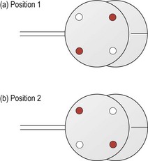
Fig. 4.11 Orientation of the cross-cylinder for axis determination in (a) ‘picture or lens 1’ and (b) ‘picture or lens 2’.
6. JCC axis determination: Set the JCC so that the minus cylinder axis and the plus cylinder axis straddle the correcting cylinder axis (Figure 4.11). With modern phoropters the JCC will click into place at this correct orientation. Ask the patient to compare this initial lens position ‘Lens 1’, to its flipped counterpart, ‘Lens 2’ (Figure 4.11).
7. Adjust the correcting cylinder axes toward the minus cylinder axis (red dot) of the preferred lens position (1 or 2). The amount of rotation typically depends on the size of the cylinder (Table 4.1). This can be tempered by the response from the patient (see online video 4.12) . For example, if the JCC response with a 1.00 DC was very strongly in favour of one lens/picture (and particularly if the visual acuity was down so that you suspect the astigmatism after objective refraction was incorrect by a significant amount), it may be better to rotate the cylinder by 10° or 15° rather than the 5° suggested in the table. Similarly, if the JCC response was weak and hesitant, you could make less of a change than that suggested in Table 4.1.
8. Repeat the comparison (use ‘Lens 3 …. or Lens 4’, etc., to indicate to the patient that you are not just repeating the previous presentation) and continue to adjust the axis dependent on the results. The amount of rotation of the cylinder should be reduced (approximately halved) at each change of the direction of rotation. For example, if a 0.25 DC was initially at 90°, and the JCC indicated a clockwise rotation was required, move it to 60° (Table 4.1). If the JCC then indicates that an anti-clockwise rotation was required, move the cylinder by 15° to the 75° position. Try to keep a mental note of previous decisions made with the JCC to help you ‘zero-in’ on the final axis. In the example above, if the JCC suggested another anti-clockwise movement was required, there would be little point in rotating the cylinder to 90° as the JCC has already been used at this position. Either 80° or 85° would be more appropriate. Continue until the patient notices no difference between the two lens positions (and you have bracketed the axis).
9. If the two initial lens positions appear the same, confirm that the current axis is the correct one by rotating the cylinder axes off by about the amount suggested in Table 4.1 and have the patient compare Lens 1 and 2 (see online video 4.10) . The patient should return you to the initial axis orientation if it was correct. If they do not, they may have a range of cylinder axes positions in which the JCC positions look the same. In this case, you need to determine the extent of this range and place the cylinder axis in the middle of it (e.g., if the patient reports that the JCC positions look the same at 20° through to 40°, place the cylinder axis at 30°). You could also use a ±0.50 JCC with such patients.
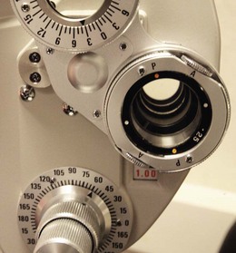
10. JCC power determination: Adjust the JCC so that either the minus axis (red dot) or plus axis (white dot) parallels the trial frame/phoropter cylinder axis (the JCC will click into place with modern phoropters; Figure 4.12). Have the patient compare the relative clarity of Lens 1 to Lens 2 (Figure 4.13).
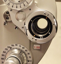
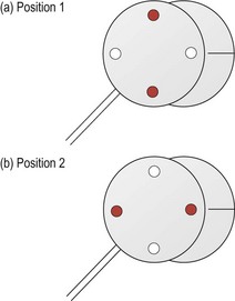
Fig. 4.13 Orientation of the cross-cylinder for power determination in (a) ‘picture or lens 1’ and (b) ‘picture or lens 2’.
11. If the patient reports that there is no perceived difference between the images shown, do not assume you have the correct power. Remove −0.25 D from the cylinder and repeat the comparison. If the initial lens was correct the patient will call for more cylinder by choosing the lens that has the minus cylinder axis (red dot) parallel to the phoropter axis. In this case, increase the cylinder power to its original amount. However, if you remove −0.25 DC and the patient again reports that there is no difference between the two pictures, the patient may have a range of cylinder powers in which the JCC positions look the same. In this case, you need to determine the least amount of cylinder for which the patient notices a difference with the JCC. You could also use a hand-held ±0.50 JCC with such patients.
12. If there is a difference between Lens 1 and 2, then add minus cylinder (−0.25 D) if the patient prefers the minus cylinder axis (red dot) parallel to the phoropter axis. Remove −0.25 DC if the patient prefers the plus cylinder axis parallel to the phoropter axis. Continue this process until no difference between Lens 1 and 2 can be detected or until the power has been bracketed to less than a 0.25 D (choose the least minus cylinder).
13. For each 0.50 D change in cylinder power, change the sphere power by 0.25 D in the opposite direction (e.g., if you add −0.50 DC, then add +0.25 DS before comparing the lens positions). This is to ensure that the circle of least confusion remains on the retina.
4.10.4 Poor JCC technique: ‘Nudge, nudge, same’
 :
:1. Accepting an initial response of ‘same’ to indicate that your retinoscopy cylinder axis was correct can mean that you would be incorrect by 90°! For example, if the retinoscopy result gave a cylinder at 20°, yet the real cylinder was at 110°, the patient is likely to respond that the two images of the JCC look the same. Note that the JCC axes would be at 65° and 155° with a cylinder axis at either 110° or 20°. Unfortunately, it is not uncommon for novices to be incorrect in cylinder axis by 90° in retinoscopy.
2. Some patients have a range of axes over which they believe that the two JCC images look the same. In these cases, the axis should be placed in the middle of the range. For example, if the patient responded ‘same’ from 150° to 180°, the cylinder should be placed at 165°. Using the first ‘same’ response would likely place the cylinder axis at ~150° or 180°.
3. Patients can provide unreliable responses, especially during the first few presentations, so that a ‘same’ response could just be an incorrect response. You can be far more confident that you have obtained the correct cylinder axis if you have ‘bracketed’ it.
4.10.5 Examples of efficient JCC procedures for cylinder axis
 .
.1. Use appropriate changes in axis and ‘bracket’ the final result
Cylindrical axis before JCC: −1.25 × 80
(i) The JCC is set so that the minus cylinder axis (position 1: 35°, position 2: 125°) and the plus cylinder axis straddle the correcting cylinder axis of 80° and is clicked into place at this orientation. The patient choice (minus cylinder axis at 35°) indicates that the correcting cylinder should be moved clockwise. As the cylinder is −1.25 DC, it should be moved clockwise by 10° (Table 4.1) from 80° to 70°.
(ii) The patient choice indicates that the correcting cylinder should be moved clockwise again. Move it from 70° to 60°.
(iii) The patient choice indicates that the correcting cylinder should be moved anti-clockwise. This is a change in direction of movement of the JCC, so the amount of change of the correcting cylinder should be halved to 5°. The correcting cylinder should be moved 5° anti-clockwise to 65°.
(iv) The patient cannot discriminate between the two lens positions and the true cylinder axis position has been determined. Note that this axis has been bracketed. i.e., appropriate responses with the JCC have been obtained slightly above (clockwise from 70°) and slightly below (anti-clockwise from 60°) the final axis.
Cylindrical axis changes during JCC were 80 − 70 − 60 − 65.
Cylindrical axis after JCC: −1.25 × 65
2. Do not accept that an initial ‘same’ response suggests that the axis is correct.
(i) The correcting cylinder is -0.75 × 80°. The JCC is set so that the minus cylinder axis and the plus cylinder axis straddle the correcting cylinder axis of 80° and is clicked into place at this orientation. The patient cannot discriminate between the two lens positions and responds that they look the ‘same’. However, there is no firm indication that the true cylinder axis position has been determined as this axis has not been bracketed (section 4.10.4).
(ii) Move the cylinder axis by ~10° to 70° as the cylinder power is −0.75 (Table 4.1) and if correct the ‘same’ response suggests you are close to the final axis. The patient choice indicates that the correcting cylinder is anti-clockwise from 70°.
(iii) To confirm 80° as the final cylinder, move the cylinder axis to 90°. The patient choice indicates that the correct cylinder is clockwise from 90°.
(iv) Appropriate responses with the JCC have been obtained slightly above (clockwise from 90°) and slightly below (anti-clockwise from 70°) the final axis. The final axis has therefore been ‘bracketed’ by appropriate responses.
4.10.7 Adaptations for older patients
1. Use longer presentation times: Processing speed slows significantly with age,20 so provide a longer presentation time for both Lens 1 and Lens 2 than you would normally do for younger patients.
2. Use a ±0.50 JCC: If a patient with reduced VA is unable to tell any difference with the ±0.25 JCC, then use a ±0.50 JCC or even a ±1.00 JCC. A hand-held cross cylinder may be held over the phoropter in these cases.
3. Ask for a response from two options: It can be difficult for all patients and particularly older patients to make a decision when there are three possible responses of ‘Lens 1’, ‘Lens 2’ or ‘the same’. Some clinicians just ask whether the image seen with Lens 1 or Lens 2 is better. Using such a technique, the patient often indicates at some point that the two presentations look the same. Alternatively, after the patient has confidently provided several responses of ‘Lens 1’ or ‘Lens 2’, they may hesitate and appear unsure. At this point you could ask whether the two presentations look the same.
4.10.8 Recording
The results of the JCC are not recorded as the technique is just part of the subjective refraction (section 4.6).
4.10.9 Interpretation
Solsona retrospectively analysed 51,000 patients with astigmatic corrections greater than or equal to 0.75 D and found that 67% had mirror symmetry within 10°.7 This means that the two axes should add up to approximately 180°: Both axes could be 90° or both axes 180° (i.e. 0° and 180°); one axis 175°, the other 5°; one axis 20°, the other 160°; one axis 45°, the other 135°, etc. You may wish to recheck astigmatic axes that do not follow this pattern, particularly if one axis has changed significantly from a previous examination or is significantly different from the retinoscopy result.
Typically, younger patients will have ‘with-the-rule’ astigmatism, with a steeper vertical meridian (minus cylinder axis between 160–20), likely due to pressure from the eyelids. This lid tension decreases slowly with age, so that with-the-rule astigmatism slowly disappears and older patients typically have ‘against-the-rule’ astigmatism (minus cylinder axis between 70–110).5 Note that this change with age is slow and any significant refractive correction changes between eye examinations 1–3 years apart are likely to be largely spherical in nature. Significant changes in astigmatism over a 1–3 year period are likely to be due to refraction error at test or retest or possibly due to ocular pathology such as keratoconus, cortical cataract, chalazion, etc., causing significant astigmatic changes.3
4.10.10 Most common errors
1. Using the ‘nudge, nudge, same’ technique (section 4.10.4).
2. Using too short a presentation time in older patients. Using a longer presentation time, and repeating the two views when the patient is unsure, can actually provide a quicker determination of the cylinder axis and power as the responses provided are more reliable.
3. Presenting the target for longer in position 2 compared to position 1 or vice-versa. The patient should see the two presentations for the same amount of time.
4. Poor alignment of the JCC with the correcting cylindrical lens in the trial frame. This can lead to problems in determining the cylinder axis. Check that the handle of the JCC is in alignment with the axis of the correcting cylindrical lens when determining the cylinder axis.
5. Believing that removal of the JCC in trial frame refraction is an option, i.e., offering ‘position 1…2…or (removing the JCC) the same’.
4.10.11 Alternative techniques: Fan and block, sunburst, Raubitschek arrow, etc.
There are a variety of fan-shaped tests but all use a similar methodology. Those tests that do not include axis refinement using a rotating arrow or dial are not described as they provide poor estimates of cylinder axis and power.28
2. Starting with the objective refraction result, perform BVS (sections 4.7 and 4.8; keep the cylinder found during retinoscopy in the phoropter/trial frame).
3. Remove the minus cylinder estimate from retinoscopy so that the patient is fogged (techniques that suggest you measure VA to estimate the approximate cylinder power with the best vision sphere result, assume that you do not have any estimate of the cylinder from retinoscopy or autorefraction or the patient’s old glasses or keratometry and this is a very rare situation).
4. In case the retinoscopy cylinder estimate was incorrect (and too low), add +0.50 DS to ensure that both focal lines are in front of the retina (this allows for an underestimation of the cylinder during retinoscopy of 1.00 DC). Larger amounts of additional plus can be used, but then it is likely that you will need to subsequently reduce this before the patient is able to see a difference in clarity in some of the lines on the fan.
5. Present the ‘fan’ to the patient and ask them to indicate which lines of the fan are clearest, if any (Figure 4.9). It can be helpful to indicate how these lines could be described by the patient: ‘Are the lines at 2 o’clock clearest, or those at 10 o’clock?’
6. If the patient states that all the lines are equally clear, reduce the spherical correction in +0.50 DS steps and repeat the presentation of the fan.
7. If the patient states that some lines are clearer than others, rotate the arrow (or ‘T’ or dial) to point in the same direction as the clearest lines indicated by the patient.
8. Fine tune the arrow position by ensuring that the two sides of the arrow or dial are equally clear.
9. Ask the patient to compare the two blocks (Figure 4.9; or lines on the different parts of the T, etc.) and the blocks/lines in line with the arrow should be clearer than those that are perpendicular.
10. Increase the cylinder power until the two blocks or two parts of the T are equally clear. Provide the lowest cylinder power if the two blocks cannot be exactly matched in clarity.
11. Reduce the plus/increase the minus power of the sphere until maximum VA is achieved.
4.11 Binocular balancing
During monocular refraction, the occluder can induce proximal accommodation and accommodation due to vergence (by acting like a cover test) in the eye behind it, so that the eye being refracted may also be accommodating.29 A binocular balance of accommodation is typically performed after a monocular refraction to relax and balance accommodation in the two eyes. The test need not be performed if the patient does not have binocular vision or if the patient is older than ~60 years of age or pseudophakic and has no accommodation, unless a recheck of the best vision sphere is thought to be useful.
4.11.1 Comparison of binocular balancing tests
There has been little comparison of the various binocular balancing techniques in the research literature and the study by West and Somers provides limited information and further study is needed (section 1.1.2).30 Some tests directly compare the vision in the two eyes (prism-dissociation balance, alternate occlusion) and are directed towards balancing accommodation while others are based on binocular refraction techniques (e.g., polaroid, monocular fogging, Humphriss) and determine the spherical correction in conditions close to the patient’s normal viewing situation.
The alternate occlusion test continues to use an occluder, acts like a cover test and does not allow binocularity, so that its usefulness over monocular refraction seems limited. The prism dissociated binocular balance is also fully dissociated, so that fusional vergence is not present and accommodation may not be at the same level when binocular.29 Both these tests need the patient to have equal VA in the two eyes to be able to provide accommodative balance. Other tests, such as the Polarisation balance, monocular fogging and Humphriss immediate contrast test, are minimally dissociated and aim to determine the spherical correction in conditions similar to the patient’s normal viewing situation so that vergence and pupil size are in their normal binocular state. Polaroid tests on computer-based systems are best if they include three lines of VA with a fusion lock line that is seen by both eyes. With only two lines, one seen by the right eye and one by the left, the lines may float freely and cause confusion. Fogging of one eye by a small amount in the monocular fogging technique has several advantages in that it relaxes accommodation and suppresses central vision whilst maintaining peripheral fusion. Both the polaroid dissociated (or prism-dissociated) balance tests can be used with the duochrome (section 4.9), where balance is achieved by gaining the same endpoint in both eyes (i.e. red = green in both eyes, or ‘just on the red’ in both eyes).29 The duochrome and monocular fogging techniques can balance accommodation in patients with unequal monocular VA. The Turville Infinity Balance, which is not described here, appears to be rarely used nowadays, although it has the advantage that the measurement procedure inherently includes a screening test for decompensated heterophoria and suppression. However, it requires physical movement of a septum on a mirror, which makes it somewhat cumbersome.
4.11.2 Procedure: Polaroid binocular balance of accommodation
1. Place the polarised filters before both eyes.
3. Ask the patient if the letters are clearer on the line seen by the right eye or left eye or if they are both the same.
4. If one line is clearer, add +0.25 DS to that eye until the two monocularly seen lines are equally blurred.
5. If a balance cannot be achieved, use the lenses that provide the best vision to the dominant eye (section 5.11.2 for dominancy testing) or the closest match.
6. Remove the polarised filters.
7. Remove the fog in binocular 0.25 DS steps until you obtain maximum visual acuity.
8. If the patient can read the bottom line of your chart (and this is larger than 6/3 or 20/10), you can allow extra minus/less plus that makes your bottom line of letters ‘clearer’. Ensure that the bottom line of letters is ‘definitely clearer and not just smaller and blacker.’
4.11.3 Procedure: Monocular fogging balance (modified Humphriss)

1. Fog the left eye until the visual acuity is reduced by 3 or 4 lines less than the tested eye. Typically +0.75 DS or +1.00 DS is required.
2. Repeat the best vision sphere assessment using the plus/minus technique (section 4.8).
3. If significant positive power needs to be added, such as for some patients with latent hyperopia, it is likely that this will relax accommodation in both eyes. To ensure that the amount of fogging lens is still effective add additional plus power to the left eye and check that visual acuity is blurred by 3–4 lines.
4. Remove the fog from the left eye then fog the right eye by 3 or 4 lines and repeat the plus/minus best vision sphere technique for the left eye.
4.11.4 Procedure: Humphriss Immediate Contrast
The following procedure is based on the technique described by Humphriss.31
1. Fog the left eye until visual acuity is reduced by 3 or 4 lines less than the tested eye. Young patients with normal vision would usually require adding +0.75 DS or +1.00 DS to give a visual acuity of 6/9 to 6/12 (20/40).
2. Ask the patient to look at the smallest line they can see on the letter chart (Humphriss suggested using a 6/12 or 20/40 letter but few clinicians follow this and the rationale is not clear).
3. Place a +0.25 DS lens in front of the right eye for about 1 second (or longer if the patient appears to need more time) and then replace this with a −0.25 DS for about 0.5 seconds (or half the time given to the +0.25 DS lens).
4. Ask the patient ‘Are the letters clearer with Lens 1……..or Lens 2?’
5. Examples of the situation occurring in a fully corrected, slightly over-minused and slightly over-plussed eye are shown in Table 4.2. The image seen with each lens is determined by the clarity of the image in the clearer eye, modified by the effects of binocular summation.
Table 4.2
An indication of the changes made to the clearer eye and the interocular difference when either +0.25 DS or −0.25 DS is used with a +1.00 fogging lens in the Humphriss immediate contrast technique
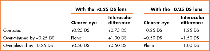
6. If the patient immediately reports that the −0.25 DS is definitely clearer, repeat the demonstration of the lenses and ask if the −0.25 DS ‘is definitely clearer or just smaller and blacker’. Only add −0.25 DS if the patient immediately reports that the lens is definitely clearer.
7. If the patient reports after some consideration that the −0.25 DS lens is clearer, do not add −0.25 DS.
8. If the patient reports that the +0.25 DS is clearer or that there is no difference, add +0.25 DS to the refractive correction.
9. Because you have added +0.25 DS to the right eye, it is assumed that accommodation will have been relaxed in both eyes. To ensure that the amount of fogging lens is still effective add +0.25 DS to the left eye.
10. Continue to compare the −0.25 DS and +0.25 DS until the +0.25 DS is immediately rejected.
11. Repeat the procedure on the left eye with the right eye fogged.
4.11.5 Procedure: Prism-dissociated blur balance of accommodation

1. Occlude the left eye (or ask the patient to close their eyes; the increasing diplopia produced by the prisms can be distressing) and isolate the 20/40 (6/12, 0.5) row of letters.
2. Introduce the Risley prisms before both eyes, so that there is 3Δ base down before one eye and 3Δ base up in front of the other eye. It is important that equal prism before each eye is used to equalise any image degradation by the prisms.
3. Add +1.00 DS to the right eye and check whether the 20/40 line is blurred. They should be blurred, but readable. Add further plus power in +0.25 D steps until the 20/40 is just blurred.
4. Remove the occluder (or ask the patient to open their eyes) and ask the patient if they see two 20/40 (6/12) lines of letters, one above the other.
5. If the patient cannot see both lines, first check that both apertures are open. If they are, cover each eye in turn, so that the patient can see the position of the line seen by each eye. The patient should then be able to see both targets at the same time. If the patient still cannot see two lines, then one eye is likely suppressing and a binocular balance is not required.
6. Add plus lenses in +0.25 DS steps to the left eye until both eyes have equally blurred images.
7. If a balance cannot be achieved, use the lenses that provide best vision to the dominant eye (section 5.11.2 for dominancy testing) or the closest match.
8. Remove +0.25 DS from both eyes, and ask whether the two images remain equally blurred (you may need to isolate the 20/30, 6/9 line for this comparison). If one image is clearer, add +0.25 DS to the eye with the clearer image until both eyes have equally blurred images. If a balance cannot be achieved, use the lenses that provide the closest match.
9. Remove the Risley prisms (ask the patient to close their eyes while this is done) and display the bottom part of the visual acuity chart. Check the visual acuity to ensure that the best acuity line has not been achieved.
10. Remove the fog in binocular 0.25 DS steps until you obtain maximum visual acuity. If the patient can read the bottom line of your chart (and this is larger than 20/10, 6/3), you can allow extra minus/less plus that makes your bottom line of letters ‘clearer’. Ensure that the bottom line of letters is ‘definitely clearer and not just smaller and blacker.’ This should be no more than −0.50 DS extra than the refractive correction used to see 20/20 (6/6).
11. Measure monocular and binocular VAs, especially if the binocular difference is more than 0.25 D from the monocular subjective. If monocular visual acuity is reduced in one eye following this procedure, recheck the results.
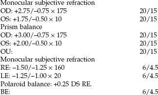
4.11.8 Most common errors
1. Binocularly balancing patients over 60 years of age and pseudophakes who have no accommodation to balance.
2. Binocularly balancing patients who do not have binocular vision or who have unequal visual acuity.
3. Prism dissociated blur: Using a truncated VA chart and not allowing extra minus/less plus that makes your bottom line of letters ‘clearer’. This can lead to an over-plussed/under-minused refractive correction, particularly when associated with a MPMVA technique in older patients.22
4. Monocular fogging and Humphriss Immediate Contrast: Using too large a fogging lens, such as +1.50 DS or +2.00 DS (as used as a working distance lens during retinoscopy). It is possible that this degree of retinal image degradation could cause the accommodation system to adopt an open-loop response leading to stimulation of accommodation by around 1.00 D, rather than a relaxation of accommodation.32
5. Monocular fogging and Humphriss Immediate Contrast: Failure to modify the fogging lens when +0.50 DS or more has been added to the fellow eye.
6. Humphriss Immediate Contrast: Presenting the +0.25 DS and −0.25 DS for an equal amount of time.
4.12 Binocular subjective refraction
Subjective refraction should be performed under conditions that simulate the patient’s normal distance viewing situation (including vergence, accommodation and pupil size; although differences in pupil size do not affect refractive correction33,34) as closely as possible. A major advantage of binocular refraction over monocular refraction is better control over, and greater relaxation of, accommodation. This is particularly important when measuring the refractive error in patients with hyperopia, pseudomyopia and antimetropia. In monocular refraction, the occluder can also act like a cover test and manifest any horizontal heterophoria (with associated changes in accommodation) and any vertical or cyclophoria that could lead to an incorrect assessment of astigmatism. Binocular refraction is also preferred in patients with latent nystagmus as the occluder used in monocular refraction manifests the nystagmus and makes subjective refraction difficult. Finally, binocular refraction has the advantage of being slightly quicker than monocular refraction because no binocular balancing is required.
Unfortunately, binocular refraction is not possible with a small number of patients. For example, some patients with highly dominant eyes find it very difficult to give good subjective responses with their non-dominant eye during binocular refraction, and these patients are better refracted monocularly. In addition, some binocular refraction techniques provide difficulties to some patients. For example, patients with cataracts can find polaroid binocular refraction difficult because of the reduced illumination provided by the polarised filters. Finally, binocular refraction only works efficiently if the refractive corrections are reasonably close to the optimal correction at the start of the procedure. It is therefore often used for contact lens over refraction where the residual prescription is likely to be small. However, inexperienced students, whose retinoscopy skills still need practice, should use monocular refraction until their retinoscopy skills improve. Clearly, the technique can only be used with patients that have binocular vision. Refraction can be performed binocularly using monocular fogging (modified Humphriss), Humphriss Immediate Contrast (HIC), and polaroids. The polaroid, monocular fogging and HIC techniques for binocular balancing have already been described and their advantages discussed. Monocular fogging refraction can only be used with the plus/minus technique (section 4.8) and JCC, as MPMVA determination of the best vision sphere and fan and block determination of astigmatism require the tested eye to be blurred. Polaroid refraction, with for example the AO Vectographic system, uses a chart that has letters on one half polarised at, say, 90 degrees and letters on the other half polarised orthogonally (in this example at 180 degrees). The patient views the chart with polaroid filters that transmit the letters from one half of the chart to one eye and the other half of the chart to the fellow eye. Light from the background of the chart and a central vertical bar is transmitted to both eyes. This technique provides all the advantages of binocular refraction. Disadvantages include that the light transmitted by the polarising filters is reduced by 50%. This makes the letters of slightly lower contrast than normal and this can be a problem when refracting patients with some conditions such as cataract. Another problem is that it can be difficult to economically produce polarised letters in very small sizes below 20/20 or 20/15.28
4.12.1 Procedure: Monocular fogging
1. Begin with the net retinoscopy sphere-cylinder before each eye. The patient’s distance PD should already be set in the phoropter or trial frame, which should be level and positioned appropriately.
2. Explain the procedure to the patient: ‘During this test, I will place various lenses in front of your eye to find the lenses that give you the best vision. Don’t worry about giving a wrong answer as everything is double checked.’
3. The subjective refraction traditionally begins on the right eye (or the poorer eye if you determine there may be a poor eye from the case history).
4. Occlude the right eye and fog the left eye until the visual acuity is reduced by 3 or 4 lines less than the tested eye. Typically +0.75 DS or +1.00 DS is required. Remove the occluder from the right eye.
5. Determine the best vision sphere (sections 4.7 or 4.8) and cylinder power and axis using the JCC (section 4.10). Check the end result sphere using the duochrome (section 4.9) and measure VA.
6. Remove the fogging lens from the untested eye and fog the right eye. Determine the optimal subjective refractive correction in the left eye using the plus/minus technique and JCC and measure VA.
7. Remove the fogging lens and measure binocular VA.
8. Compare the monocular VAs with the habitual VAs and age-matched norms and measure the vertex distance if required (section 4.12.3).
4.12.2 Procedure: Polaroid binocular refraction
1. Begin with the net retinoscopy sphere-cylinder before each eye. The patient’s distance PD should already be set in the phoropter, which should be level and positioned appropriately.
2. Explain the procedure to the patient: ‘During this test, I will place various lenses in front of your eye to find the lenses that give you the best vision. Don’t worry about giving a wrong answer as everything is double checked.’
3. The subjective refraction traditionally begins on the right eye (or the poorer eye if you determine there may be a poor eye from the case history).
4. Place the polarised filters before both eyes and direct the patient to the chart that is seen by the right eye
5. Determine the optimal subjective refractive correction in the right eye using your preferred techniques for best vision sphere and astigmatism assessment (sections 4.7 to 4.10) and measure VA.
6. Repeat for the left eye after directing the patient to the chart that is seen by the left eye.
7. Remove the polarised filters and measure binocular VA.
8. Do not perform a binocular balance as accommodative balance can be assumed.
9. Compare the monocular VAs with the habitual VAs and age-matched norms and measure the vertex distance if required (section 4.12.3).
4.12.3 Check tests after refraction
1. Compare monocular VAs after your refraction with the patient’s vision or habitual VAs as appropriate. If the VA is better with the patient’s spectacles, then it is likely that your subjective result is incorrect. Repeat the subjective refraction (students should perhaps call their supervisor).
2. Compare the VA with the present subjective refraction with age-matched normal data (Table 3.1). If the VA is worse than expected, or worse in one eye compared to the other, remeasure the VA with a pinhole aperture. If the VA improves with the pinhole, either the patient has media opacity, typically cataract that is being bypassed by the pinhole, or the subjective refraction is not optimal and should be repeated. Note that visual acuity will not always improve with cataract, particularly if the opacity is dense and central.
3. If the final refractive correction in either eye is above 5.00 D mean sphere equivalent (MSE, the sphere plus half the cylinder; e.g., −4.75/−1.50 × 180 has an MSE of −5.50 D, +5.50/−2.00 × 90 has an MSE of +3.50 D), then measure the vertex distance. This is the distance from the back surface of the lens nearest the eye to the apex of the cornea. Back vertex distance can be read from the millimetre scale on the side of the trial frame, from the back vertex distance periscope on the side of the phoropter, or by using a vertex distance gauge.
4.12.4 Adaptations to the standard procedure
4.12.5 Recording
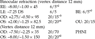
Make sure that the prescription details that you provide to patients are clearly legible. Illegible prescription forms have been reported as a surprisingly common error in optometric practice.6
4.12.6 Interpretation
A subjective result that is significantly less positive (more negative) than the retinoscopy result or a subjective result more minus than suggested by unaided visual acuity could indicate latent hyperopia or pseudomyopia and a cycloplegic refraction may be required (section 4.13).
The difference between the patient’s own spectacles and the subjective refraction should be compatible with the difference between the habitual (with own spectacles) and optimal VAs. For example, if the patient has a visual acuity of 6/12 in their spectacles and 6/4.5 after subjective refraction, you could expect the subjective refraction to be 1.00 DS more myopic than the spectacle correction (−0.25 ≈ 1 line of logMAR visual acuity). Thus, a 6/12 VA with a spectacle correction of −1.00/-0.50 × 180 would suggest a refractive correction of −2.00/−0.50 × 180. If the subjective refraction was −2.50/−0.50 × 180 or even −3.00/−0.5 × 180, this could suggest you have over-minused the subjective refraction. Changes in hyperopic refractive errors are more difficult to explain in this way, as they are dependent on the amount of accommodation the patient has (and therefore their age). Changes in astigmatism that are not due to pathology are usually small.5 Patients with refractive error change that is a result of cataract or other eye disease will not typically follow the same rules for improvement in visual acuity (e.g., nuclear cataract can cause a 1.00 D myopic shift with only a 1–2 line improvement in visual acuity).
A patient with reduced VA (typically in both eyes) and a retinoscope result that indicates emmetropia or slight hyperopia may have non-organic visual loss (also called functional or psychogenic visual loss).35,36 It may be accompanied by visual field defects, which are often tubular.36 In young children, this is often because the child wishes to wear glasses (perhaps their best friend or a parent wears glasses), but can be due to social problems at home or school and can include sexual abuse.35,36 In adults, non-organic visual loss is linked with trauma (typically head trauma), chronic pain conditions including migraine and underlying minor psychiatric problems that included feelings of stress, anxiety and depression.36 A useful test, particularly with children, is to perform a subjective refraction using a variety of lenses that have no effect on VA (such as a combination of +0.25 DS and -0.25 DS in a trail frame) and encourage the patient to read further down the VA chart. In many cases, the patient can be encouraged to read normal or near normal VA in this way and if ocular health appears normal, a diagnosis of non-organic visual loss can be made and reassurance given to the child and parent (section 2.4.2).
4.12.7 Most common errors
1. Not monitoring the visual acuity to ensure that a change in lens power results in the expected change in visual acuity.
2. Using poor patient instructions or leading questions.
3. Not checking a subjective refraction that leads to sub-optimal visual acuity with a pinhole.
4. Not recording the vertex distance with a refractive correction above 5.00 DS.
4.13 Cycloplegic refraction
4.13.1 When is a cycloplegic refraction necessary?
The following can indicate the need for a cycloplegic refraction:
• Accommodative problems suggested in the case history (for example, difficulty changing focus, distance vision blur after a lot of near work).
• Patients with esotropia or convergence excess esophoria.
• Accommodative fluctuations indicated by a fluctuating pupil size and/or reflex during retinoscopy.
• A retinoscopy result significantly more positive (>1.00 DS) than the subjective result.
• A subjective result significantly more minus (>1.00 DS) than suggested by unaided visual acuity.
• A patient with myopia and esophoria.
• Patients with accommodative problems suggested by amplitude of accommodation, dynamic retinoscopy or accommodative facility testing.
Of course, cycloplegic refractions are only used with patients who have accommodation, and usually with those who have the most accommodation: children. The least toxic drug and the lowest dosage (concentration and number of drops) that will produce sufficient cycloplegia should be used. Other assessments of the accommodative system are required (sections 6.9 to 6.11) if the cycloplegic refraction result is unrevealing.
4.13.2 Adverse effects
The key disadvantages of cycloplegia are the temporary symptoms of blurred vision and photophobia experienced by patients. The degradation of vision is caused by the abolition of the accommodation response and increase in ocular aberrations as a result of dilated pupils. Adverse effects and allergic reactions to cyclopentolate are rare and the severe reactions such as psychosis, hallucinations, ataxia and incoherent speech have only been reported for the 2% concentration (or multiple drops of 1%), which should be avoided.37 In all cases, choose the drug with the least possible adverse effects and the lowest concentration that will allow you to efficiently attain the cycloplegia that you require. For example, research has suggested that cyclopentolate 1% is sufficient to produce good cycloplegia, with an effect similar to atropine 1%, in patients with accommodative esotropia and that tropicamide 1% is as effective as cyclopentolate 1% for the measurement of refractive error in most healthy, non-strabismic infants.38,39
4.13.3 Procedure
1. It is often useful to attempt a ‘dry’ (non-cycloplegic) binocular refraction first as this can provide very useful information (interpretation, section 4.13.5).
2. Obtain informed consent: Explain why you want to use a cycloplegia and explain the visual effects (near vision blur, pupil dilation and increased light sensitivity) and their duration (dependent on the drug used and the dosage). Also tell the patient that the drops will sting a little initially, but that the stinging will disappear.
3. Unless there are indications that suggest the possibility of a narrow anterior angle (such as high hyperopia or anterior segment abnormality), it may be unnecessary to conduct a full examination of the anterior angle prior to cycloplegic instillation. Cycloplegia is typically performed on young children who will have wide anterior angles due to the thin nature of the lens in childhood. The ‘shadow test’ (section 7.5) is easier to perform with young children and will often suffice.
4. Instil an appropriate cycloplegic drug (section 7.8).
5. Ask the patient to sit in the waiting room for about 20 (tropicamide) to 30 minutes (cyclopentolate) until the drug has obtained maximum or near maximum effect. Check that sufficient reduction in accommodation has been obtained by quickly checking the patient’s amplitude of accommodation. Anisocoria could indicate unequal cycloplegia. Add another drop if sufficient accommodation reduction has not been obtained.
6. Perform retinoscopy and/or autorefraction in the usual way. If subjective refraction is not possible, it is useful to have both objective measures. When performing retinoscopy, you must concentrate on the central 3–4 mm of the pupil. The peripheral part of the pupil may show a different reflex motion due to aberrations and these should be ignored. Often, a cycloplegic refraction is performed on young children, so that the refraction ends after retinoscopy and/or autorefraction.
4.13.4 Recording
2.30 pm: 2 drops cyclopentolate 0.5%
Retinoscopy, 3.00 pm: RE: +2.00 DS 6/6−2
LE: +1.75/–0.50 × 180 6/6−3
1 drop tropicamide 1%, refraction 20 minutes after instillation.
Retinoscopy: OD: +1.75/–1.00 × 170 20/20−2
OS: +1.25/–0.50 × 7.5 20/20−1
Subjective: OD: +1.50/–1.00 × 170 20/20−1
OS: +1.00/–0.50 × 7.5 20/20
4.13.5 Interpretation
Clearly there are limitations to many of the measurements made in ‘dry’ (non-cycloplegic) refractions of patients with excessive or fluctuating accommodation, but there are also limitations in ‘wet’ (cycloplegic) refractions and all must be considered when prescribing and deciding on the best patient management. During wet retinoscopy it is vital to concentrate on the reflex in the central 3–4 mm and ignore the reflex in the periphery that is influenced by peripheral aberrations. For this reason it can be particularly useful to obtain two objective measures of cycloplegic refractive and use both retinoscopy and autorefraction. Autorefraction provides a particularly accurate assessment of refractive correction under cycloplegia in children.15,16 Also note that the cycloplegic VA is likely to be slightly reduced compared to the VA after a dry refraction due to the peripheral aberrations.
| Dry retinoscopy: | RE: +1.50/–0.50 × 165 | 6/18−1 |
| LE: +1.75/–0.75 × 15 | 6/12−2 | |
| Dry subjective: | RE: –0.25/–0.50 × 170 | 6/5 |
| LE: Plano/–0.75 × 15 | 6/5−2 | |
| Autorefraction: | RE: Plano/–0.50 × 170 | 6/6−1 |
| LE: +0.25/–0.75 × 12.5 | 6/6−2 |
This large reduction in hyperopia from retinoscopy to dry subjective is indicative of active accommodation during the subjective refraction. In this particular case the subject has become a slight pseudomyope. The difference between a pseudomyope and latent hyperope is small; both are due to accommodative spasm, but the latent hyperope is hyperopic in the dry subjective and the pseudomyope is myopic. Due to proximal accommodation effects, these types of patients provide autorefractor results more similar to the dry subjective results than to retinoscopy. Clearly a cycloplegic refraction is required:
Grade IV (shadow test), 2 drops cyclopentolate 0.5% (2.30 pm):
| Retinoscopy: | RE: +2.00/–0.50 × 180 | 6/6−3 |
| LE: +2.00/–0.50 × 180 | 6/6−2 | |
| Subjective: | RE: +1.75/–0.50 × 175 | 6/6 |
| LE: +1.75/–0.50 × 5 | 6/6 | |
| Autorefraction: | RE: +2.00/–0.50 × 165 | 6/6−1 |
| LE: +1.75/–0.75 × 10 | 6/6 |
The cycloplegic results confirm that the dry subjective and dry autorefractor results were incorrect and due to the patient’s inability to relax accommodation. What should you prescribe? The dry retinoscopy results indicate that if you prescribed the full cycloplegic result, the patient would initially see about 6/18 in each eye. Without the cycloplegic, the patient would be unable to relax accommodation and would see very poorly in the distance. This would improve over time as the hyperopic spectacles helped the patient to relax accommodation, but the blur could be a disincentive to initially wearing the spectacles and this should be considered. A compromise prescription may work:
| RE: +1.00/–0.50 × 165 | LE: +1.00/–0.75 × 10 |
This is likely to initially blur distance VA to about 6/9+, which the patient should be able to cope with, yet will sufficiently relax the accommodation to improve the patient’s symptoms. The patient should be seen within about a month and the prescription could be increased at that point if required. The effect on symptoms, visual acuity and binocular vision should be considered when deciding on the amount of hyperopia to correct in a young person with accommodation.
Even more than for routine refraction results, you should not automatically prescribe the results found in cycloplegic refraction to the patient, although this may be required for patients with accommodative esotropia. A reduced amount of plus power is usually prescribed to compensate for ciliary muscle tonus. For infants and young children, a full hyperopic correction may not be given to ensure emmetropisation is not hindered,40 and the fact that hyperopia is normal for infants.
4.13.7 Alternative procedure: Mohindra near retinoscopy
Mohindra near retinoscopy was developed as an alternative to cycloplegic refraction in children and infants.41 It may be used when a cycloplegic refraction is contra-indicated or when it is extremely difficult to instil the drops. A dim retinoscope light is used as a fixation target and seen in complete darkness it provides little stimulus to accommodation, so that patients assume their resting focus due to tonic accommodation. This is typically +0.75 DS, so that when working at 50 cm, −1.25 DS rather than the standard −2.00 DS (i.e. the working distance lens) is added to the final retinoscopy result.41 You need to dim the retinoscope light as low as possible while ensuring it still provides you with an easily visible retinoscopy reflex. Turn off all room lights and perform retinoscopy using a lens rack or individual trial case lenses. An infant will only hold a steady gaze for a short period of time, so that you need to perform the test quickly. The standard technique is to occlude the non-fixating eye using your hand or the parent’s hand. However, this can cause infants to become agitated and even begin to cry, so that performing the test binocularly may be preferable in some cases.39 Some studies that have compared Mohindra near retinoscopy with cycloplegic retinoscopy have indicated that the test is variable and should not be used while others have suggested that the test is comparable to cycloplegic retinoscopy.39,42 It would appear that to become competent with the technique, it needs to be performed regularly and this is a disadvantage for the primary care optometrist who only occasionally examines an infant.39 Saunders and Westall recommend adding −0.75 DS for infants (<2 years) and −1.00 DS for children (over 2 years) rather than the original −1.25 DS.42
4.14 The reading addition
4.14.1 Presbyopia and the reading addition
About the age of 40–45 years of age (earlier for some ethnic groups, people with short arms or working distances and hyperopes, later for people with long arms/working distances and myopes) most people become presbyopic.43,44 This means that they do not have enough accommodation to be able to read or perform other near work clearly and comfortably. These patients require a positive lens addition to the distance refractive correction. This is called the reading or near addition. With increasing age and further losses in accommodation, the power of the reading addition needs to be increased. At 55–60 years of age, accommodation is essentially zero (what can be measured clinically is probably depth of focus).45 Although the average reading addition continues to increase after age 60 years, it does so at a slower rate (Figure 4.14) and is likely due to the increases in add needed by some older subjects due to a reduced working distance that is required to improve vision to compensate for reduced visual acuity.43,44,46,47
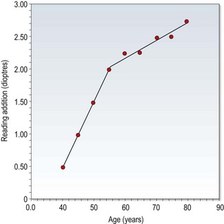
4.14.2 Comparison of tentative addition techniques
In a very useful study, Hanlon et al. determined the required reading addition of 37 dissatisfied patients who returned to a university clinic due to improper add power.48 From the case history information in the review (recheck) examination, it was determined whether the improper addition was too low or too high. For each patient, their reading addition was then determined using four methods (age, ½ amplitude of accommodation, NRA/PRA balance and binocular cross-cylinder). The percentage of additions for each test that gave the same result as the improper addition or worse (higher than an improper addition determined too high or lower than an improper addition determined as too low) was determined. They reported that the simplest and quickest test, asking the patient their age, accounted for the fewest errors (14%). The other techniques gave errors in 61% (binocular cross-cylinder), 46% (NRA/PRA) and 30% (½ amplitude) of cases. This suggests that for most patients the tentative addition should simply be based on age. Over the age of about 55 years, the patient’s working distance appears to determine their addition as accommodation is zero, so this can be a useful additional measurement in patients of this age.47
Another alternative for experienced clinicians, would be to use the patient’s symptoms with their old near correction, which is similar to the test used by Hanlon and colleagues48 to determine if additions were low or high; i.e. their gold standard test.
4.14.3 Comparison of techniques for determining the final reading add
An incorrect reading addition is a common cause of patients’ unhappiness with their new spectacles, although progressive addition lenses may have decreased the number of problems in recent years as they are more forgiving of over-plussed near corrections.22,48,49 To help to avoid such complaints, it is important to determine the range of clear near vision required by the patient and prescribe spectacles that fulfil those requirements. It is difficult to determine appropriate near working distances and ranges in a phoropter and an addition determination using a trial frame with trial case lenses is recommended.
4.14.4 Procedure: Tentative addition by age and working distance
Estimate the tentative reading addition by age and working distance.
1. For patients less than 60 years of age: Age is a good predictor of the tentative addition and suggested values that are given in Table 4.3.48 If the working distance is much less than 40 cm, increase the tentative addition appropriately. For example, if the working distance is about 33 cm increase the addition by +0.50 (the difference in dioptric terms between 40 cm or 2.50 D and 33 cm or 3.00 D). If the addition is needed for computer work and therefore the working distance is about 50–60 cm, decrease the tentative addition by about +0.50 DS.
Table 4.3
Tentative near addition estimates as a function of age up to the age of 60 years. These estimates should be adjusted for working distances. Patients with longer working distances will need a slightly smaller add and vice versa
| Patient age (years) | Tentative add (D) |
| 45 | +1.00 |
| 50 | +1.50 |
| 55 | +2.00 |
| 60 | +2.25 |
2. For patients over 60 years of age: Estimate a tentative reading addition from the patient’s working distance, with a small reduction made to allow for depth of focus.47 In this way, working distances of 50, 40 or 33 cm (dioptric values +2.00, +2.50 and +3.00) indicate tentative additions of +1.75, +2.25 or +2.50 DS, respectively, with higher additions allowing slightly more for depth of focus.47
4.14.6 Procedure: Binocular or fused cross-cylinder
1. Adjust the phoropter to the near PD, occlude the untested eye (typically OS) and position the cross-hatch target at the patient’s working distance (or 40 cm).
2. If the patient has significant astigmatism (~>1.50 DC), check that the horizontal and vertical lines of the target appear equally clear. If they do not, the astigmatic correction should be rechecked at distance. If equal clarity can still not be achieved, the astigmatic correction should be checked at near.
3. Dial the cross-cylinder (+0.50/−1.00 × 90) into the phoropter.
4. If the expected addition is high (>+2.00 DS) add +1.00 DS to the distance correction. Ask the patient to close their eyes while you dial the extra power into the phoropter.
5. Ask the patient: ‘Are the lines running up and down or those running from side-to-side clearer?’ The presbyopic patient should report that the horizontal lines are clearer.
6. Add plus lenses in +0.25 DS steps until the patient reports that the vertical lines are just clearer than the horizontal.
7. Repeat steps 2 to 6 for the other eye.
8. If the tentative addition for each eye differs, recheck the results. If they remain different, the binocular balance of the distance refractive correction should be rechecked.
9. Allow both eyes to see the target and reduce the plus power in both eyes until the horizontal and vertical targets appear equally clear.
4.14.7 Procedure: Balancing negative and positive relative accommodation (NRA/PRA)
1. Adjust the phoropter to the near PD and attach the near point card. Make sure that the optimal distance refractive correction is in place and that both eyes can view the near point card.
2. Direct the patient’s attention to letters one or two lines larger than their best near VA on the near point card. Ask the patient if they are clear. If they are not clear, add plus sphere power, +0.25 D at a time, until the patient reports that the letters are clear. This becomes the ‘initial tentative near addition’.
3. Negative relative accommodation (NRA): Add plus lenses binocularly, +0.25 D at a time, until the patient reports the first sustained blur. ‘First sustained blur’ means that the patient notices that the letters are not as sharp and clear as they were initially, even if the patient can still read them. The total amount of plus added is the NRA.
4. Return the lenses in the phoropter to the ‘initial tentative near addition’ found in step 2.
5. Positive relative accommodation (PRA): Add minus lenses binocularly, −0.25 D at a time, until the patient reports the first sustained blur. The total amount of minus added is the PRA.
6. Adjust the ‘initial tentative near addition’ that would provide equality for NRA and PRA. The adjusted figure is the ‘final tentative addition’. For example, if the ‘initial tentative near addition’ was +1.00 and sustained blur points were found with a +2.00 and a +0.50 add, the NRA would be +1.00 (2.00–1.00) and the PRA would be −0.50 (0.50–1.00). A ‘final tentative near addition’ of +1.25 DS would equalise the NRA and PRA (they would both be 0.75 DS). The change suggested by the NRA/PRA is their algebraic sum divided by two. In this example, that would be 0.50/2 = +0.25 DS.
4.14.8 Procedure: Tentative addition using the patient’s symptoms and habitual correction
This technique is best described by using some examples.
Example 1: 50-year-old patient, wearing bifocal spectacles:
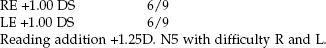
Students must remember that patients read through their near vision correction (distance refractive correction + reading addition) and NOT their reading addition. The refractive correction for near is RE: +2.25 DS, LE +2.25 DS. Given that the average change in distance spherical refractive correction with age in presbyopes who do not develop nuclear cataract is a hyperopic shift,50 a common change for the patient in the example above is for the distance correction to change to:
| RE: +1.50 DS | 6/5 LE +1.50 DS | 6/5. |
With the new distance correction of +1.50 DS, the tentative addition would be estimated as shown in Table 4.4.
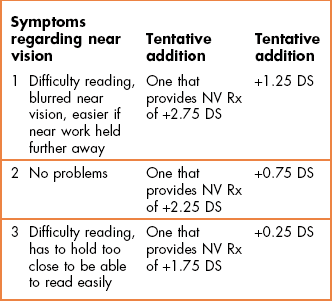
Example 2: Some patients develop nuclear cataract with age and this can lead to a myopic shift to the refractive correction.1 For example, 72-year-old patient; present spectacles and habitual VA:
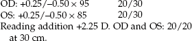
(The mean sphere equivalent of the near correction is therefore +2.25 DS.)
| RE –0.25/–0.50 × 100 | 20/15−3 |
| LE –0.25/–0.50 × 90 | 20/15−2 |
The mean sphere equivalents of the distance refractive correction is −0.50 DS, so that appropriate tentative additions would be estimated as shown in Table 4.5.
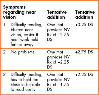
Leaving the reading addition the same at +2.50 DS, under the misapprehension that this would provide the same near correction as in the old spectacles, would leave the patient under-plussed by +0.50 DS. An under-plussed near correction, particularly in patients with nuclear cataract, has been shown to be a cause of patients rejecting new spectacles.22
4.14.9 Procedure: Final reading addition and range of clear vision (Summary in Box 4.2)

1. If you have determined the distance refractive correction in a phoropter, add the distance correction to the trial frame using trial case lenses.
2. Ask the patient if they read in normal room lighting or with an additional ‘reading’ light and only use additional lighting if the patient indicates they use such lighting at home.
3. It can be useful to use a chair without arm rests or tilt the arm rests out of the way when measuring the patient’s near working distance as they can influence the measurement.
4. Ask the patient to hold the reading card at their preferred near working distance(s) and measure this distance(s). For example, depending on the patient’s occupation and hobbies (as determined in the case history), you may need to determine at what distances a patient sews, reads and uses their computer. Instruct a patient who has complained that they habitually have to place their near work too close or too far away than they would like, to hold the near VA chart at the distance they would like to read/work at rather than the distance they may have adopted to be able to see clearly.
5. Explain the procedure to the patient: ‘I am now going to determine the power you need for your reading glasses/bifocal/progressive lens.’
6. Tentative addition determination: From one or a combination of the techniques that can be used to estimate a tentative reading addition (sections 4.14.4 to 4.14.8), obtain an estimate of the reading addition for the indicated working distance and add these lenses to the trial frame.
7. Determine the final addition for the required near working distance(s). This can be performed in one of two ways:
(a) Preferred working distance method. Ask the patient to hold the near VA chart where the lenses in the trial frame provide the best vision. Ask the patient if this distance corresponds to their preferred near working distance. If it does not, then change the reading addition appropriately: increase the addition power if you wish to decrease the working distance and decrease the addition power if you wish to increase the working distance provided. Continue this process until the working distance obtained with the trial case lenses equals their preferred working distance.
(b) Trial lens method. Direct the patient’s attention to the best acuity paragraph of text on the near chart. Add −0.25 DS and ask if the letters become clearer, more blurred or are unchanged. Confirmation lenses (±0.25 DS flippers) are useful for this task (Figure 4.15). If the acuity improves with the additional minus, then continue adding −0.25 DS until the near acuity or clarity does not improve with the additional −0.25 D. If the vision is unchanged or decreased with −0.25 DS lenses, then do not add them. Add +0.25 DS. If the visual acuity is unchanged or decreased, then do not add the lens. If visual acuity improves with the lens, then add further plus lenses (in 0.25 D steps) only as long as the near VA or its clarity improves.
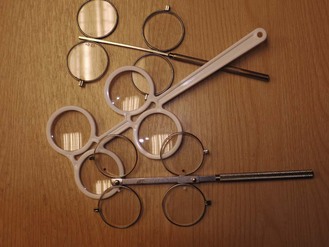
8. Determine the range of clear vision with the binocular reading add. This is important as the range decreases with higher add powers (Table 4.6). It is particularly important if you are intending that the reading addition will be used for tasks at more than one working distance.
Table 4.6
Calculations of the range of clear vision with different working distances and subjective measurements of amplitudes of accommodation
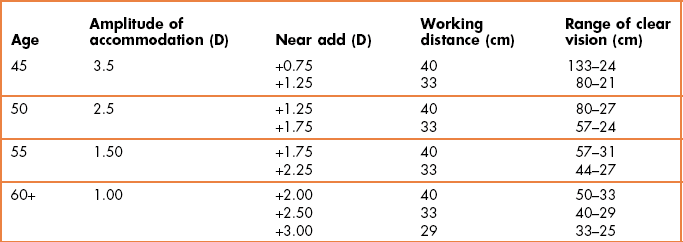
(a) To determine the near endpoint of the addition’s range, ask the patient to move the reading card slowly in until they first notice blur for the best acuity paragraph. Measure this distance.
(b) Determine the far endpoint of the addition range by asking the patient to move the card slowly away from them until the best acuity paragraph just blurs.
9. If you are unable to obtain a range that encompasses all the near working tasks that the patient has indicated they perform, you may consider that some form of progressive addition lens will provide the range of clear vision required. Alternatively, you could determine whether a compromise near addition would work. For example, the patient may have a preferred reading distance of 40 cm, but the addition that provides best clarity at this distance doesn’t provide adequate clarity for their computer at 67 cm. A compromise addition providing best clarity at 50 cm, but adequate clarity at 40 cm and 67 cm may work. Alternatively, you may need to determine individual additions for their different working distances that could be provided in several pairs of single vision spectacles or multifocals.
10. Record the final addition(s), acuity and range of clearest vision obtained with the addition(s).
Note that if this assessment ends with the patient unable to read the smallest print on your chart (e.g., N5, 20/25, 0.4 M) with their optimal near refractive correction and the patient does not have an additional ‘reading’ lamp at home, they should be strongly advised to obtain one.
4.14.11 Interpretation
Most additions are equal for the two eyes. Unequal additions require further testing: either a retest of the near addition endpoints used for each eye or a recheck of the distance binocular balance. The prescribing of unequal additions between the eyes is the exception and is rarely satisfactory. Assuming no accommodative insufficiency, the power of the addition usually increases with age in patients above 40–50 years. Patients in poor general health can ask for a higher addition than is normal for their age and working distance. In some cases a reading addition that is low for a patient’s age and working distance can indicate that the distance refraction has been over-plussed/under-minused.22 Practitioners rarely give additions greater than +3.00 D in patients with normal visual acuity. It is prudent to keep the addition as weak as possible to keep a large range of clear vision (Table 4.6).
4.14.12 Most common errors: Reading addition
1. Estimating the tentative addition of a patient over 60 based on their age and not their working distance. For example, a tall 70-year-old patient with healthy eyes and a working distance of 50 cm (dioptric value 2.00 D) will not appreciate the suggested tentative addition based on age of +2.50 D, as it is too strong.
2. Not determining the patient’s near vision needs and subsequently prescribing an addition that gives an inadequate range of clear near vision for those needs.
3. Estimating instead of measuring the near point distances with a tape measure.
4. Over-plussing a near correction by giving extra plus when it provides no change in vision.49
5. Under-plussing a near correction.22 This can particularly occur with patients undergoing nuclear cataract induced refractive changes in the distance prescription that may require a significantly increased reading addition.
4.15 Prescribing
Some optometrists, particularly if inexperienced, routinely prescribe the refractive correction determined during the subjective refraction.51 However, for some patients more experienced clinicians tend to consider both the patient’s current glasses and the subjective refraction result and prescribe a correction somewhere between these two using a selection of clinical maxims or ‘pearls’.51–54 The literature regarding these clinical maxims is based on practitioners summarising the way that they successfully adjusted refractive corrections for patients unhappy with their initially prescribed glasses. Patients returning to their optometrist to complain that they are not happy with their glasses occurs in about 1–3% of cases and clearly you want to keep this figure as low as possible.49,51 Note that these maxims are generalities and must not be used as hard and fast rules. They must NOT be used in prescribing decisions for young children, which must consider the normal refractive error for their age and the need to encourage emmetropisation and prevent amblyopia.55
4.15.1 Why not prescribe the subjective refraction result?
1. It might not be correct! It is always useful to demonstrate any refractive correction changes to the patient (section 2.4.1). Remember that the subjective refraction result can vary by up to 0.50 D for individual clinicians and up to 0.75 D between clinicians.56,57
2. The changes made may be too hard to adapt to, particularly for large changes and/or in older patients. In addition to (hopefully) improved vision, new glasses provide changes in magnification. These alter the vestibulo-ocular reflex (this makes your eyes move at exactly the same speed but in the opposite direction to your head movements to make sure that your surroundings don’t appear to move when your head moves) so that their surroundings can seem to ‘swim’ for some patients with new glasses. Cylindrical magnification changes in different meridians (which may be different in the two eyes) are even more dramatic as floors and walls can appear to slope and round objects appear oval until the patient adapts to the new glasses. Older people tend to have greater problems adapting to new glasses.53
4.15.2 Clinical maxims/pearls
1. ‘If it ain’t broke, don’t fix it’. Making changes of 0.50 D or more in patients with no symptoms who have good VA is a very common cause of patient dissatisfaction and spectacles needing remaking.58 If a patient is happy with their glasses, but would like a new frame, the only change you can make by changing the correction (particular cylinder power or axis) is to make them unhappy. Remember that the subjective refraction result is not a perfectly repeatable measurement and can vary up to 0.50 D from test to retest.56 The rule can also be used for either distance or near vision. For example, if a patient has good distance VA and is very happy with their distance vision, but needs a change at near; be wary of making large changes in the distance and just change the near addition.
2. ‘If it ain’t broke, don’t fix it much’. If a patient wants new glasses but has no symptoms and reasonable VA and you find a change of 0.50 D or more (particularly if spherical) that the patient appreciates when shown the comparison (section 2.4.1), prescribe about half the change in spherical power.58 It is likely in such cases that the patient would start to develop symptoms in the following months, so that some change seems sensible.
3. Don’t make full cylindrical power and axis changes. These can be particularly hard to adapt to for some patients, yet improvements in vision can be relatively small. Large changes in astigmatism are not common and may suggest a refraction error, cortical cataract or a lid lesion pressing on the cornea.1,3 When cylinder changes are moderate to large, generally make partial changes in cylinder power and axis (~half-way between the habitual correction and subjective result). Changes in power are more tolerable if the axes are not oblique. If there are significant VA changes and symptoms, you would be more likely to give more of the cylinder. Allow the patient to participate in the decision if possible. It can be useful to trial frame the partial correction you are going to prescribe.
4. Be careful of reducing a myopic correction. Myopia can decrease, particularly in patients aged 20–35 years, but be extremely careful of reducing a myopic correction in these patients, especially if there are no symptoms. Remember that if you are refracting at 6m or 20 ft, this is not infinity, so that patients are likely to be over-plussed by +0.17 D with a 6 m (20 ft) refractive correction. Also some low myopes tend to wear their Rx only for driving and especially at night and ‘night myopia’ may be an additional problem. Depending on the patient you may wish to prescribe the habitual correction (if it ain’t broke, don’t fix it) or prescribe half the reduction in myopia. Over-plussing the distance correction has been reported as the most common reason for failure of spectacle lens acceptance.22
5. Prescribe sufficient hyperopia to remove symptoms. You would likely prescribe the full hyperopic correction if the patient was presbyopic (or nearing presbyopia), esotropic or has esophoria (particularly convergence excess). Otherwise consider prescribing a partial hyperopic correction that is sufficient to remove the symptoms. You are unlikely to prescribe glasses to a young, asymptomatic low hyperope as they have sufficient accommodation to cope with slight hyperopia. Similarly, why prescribe the full amount of hyperopia? It makes adaptation more difficult and can make it more difficult for the patient to see without their glasses (as they get used to not accommodating as much). The amount will depend upon the patient’s symptoms, age, manifest and latent hyperopia. E.g., if fully manifest, then prescribe ½–¾ of the Rx. The older the patient, the more likely you will prescribe ~¾–full Rx. The more pronounced the symptoms, the more likely you are to prescribe more of the hyperopia. Over-plussing the distance correction has been reported as the most common reason for failure of spectacle lens acceptance.22
4.15.3 Prescribing maxims for elderly patients at risk of falls
To help elderly patients in high risk groups avoid the potentially devastating consequences of a fall, the following prescribing maxims should be followed.59 Patients at high risk of falling include those over 75 years of age, with a history of falling, using more than three medications, taking antidepressants with systemic conditions that reduce mobility and patients who may be more dependent on their vision for balance control (patients with somatosensory system dysfunction such as diabetes and/or peripheral neuropathy; or those with vestibular system dysfunction, such as Ménière’s disease).
1. Do not prescribe progressive addition lenses/varifocals and bifocals unless they have successfully worn them previously. These lenses double the risk of falling.60
2. Do not make large changes in refractive correction as these can increase the risk of falls. Limit changes to 0.75 D and keep cylindrical changes to a minimum.53,59 The danger of cylindrical lens changes causing the perception of sloping floors and walls is obvious. The dangers of spherical magnification/minification to the perceived size and position of steps and/or stair edges and the effect on the vestibulo-ocular reflex gain (the world appears to ‘swim’) is similar. Note that elderly patients adapt less well to changes in refractive correction.
3. Prescribe an additional pair of single vision distance lenses for walking outside the home and when using stairs, etc., for established multifocal lens wearers who are fit and healthy. This has been shown to reduce falls risk.59
4.15.4 Should you prescribe a small Rx?
1. If there are no symptoms related to the use of the eyes and no other indications from other tests in the eye exam, then there appears to be no need to prescribe glasses.
2. Always consider other ocular causes of the symptoms, which might not be related to the small refractive error and include inadequate convergence, accommodative facility or vergence facility and decompensated heterophoria. Also consider non-ocular causes of headaches, including tension, migraine, nasal sinusitis and hypertension. Unfortunately, tension headaches, which are a common headache, can be difficult to differentiate from ocular headaches as they are often frontal or occipital, get worse towards the end of the day and are better over the weekend.
3. If a patient has symptoms that are related to detailed vision tasks, you are more likely to prescribe a small correction if the patient does a lot of detailed work and/or if the patient has a personality that is detail-oriented, precise or intense.
4. The relative certainty of responses should help your decision of whether to prescribe a small Rx. If glasses are to be of any value, the responses during subjective refraction should be very certain, appropriate and repeatable.
5. Usually small corrections make little change to the VA (particularly if a truncated Snellen chart is used) and so basing decisions on VA improvements is usually not helpful.
6. The effect of the Rx on binocular vision tests can be helpful.61 For example, if binocular vision tests suggest that a heterophoria is decompensated with no refractive correction and compensated with it, then the spectacles are likely to help and should be prescribed.61
7. You can view prescribing glasses as a diagnostic tool. Often the only way to be certain whether the symptoms are due to the uncorrected refractive error is to prescribe it and see if the symptoms disappear. You could offer the patient a pair of basic loan spectacles to determine whether the refractive correction will relieve the symptoms. This approach is often used in medicine. However, be aware that spectacles can provide a placebo effect and relieve the symptoms for a short period before they return.
4.15.5 Should you make small changes to the refractive correction?
1. If there are no symptoms and a small change to the refractive correction and the patient wants a new frame, it may be better to stick with their old correction unless a significant improvement in VA over their old correction can be obtained (‘If It Ain’t Broke, Don’t Fix It’.).
2. Consider the points in section 4.15.4, in particular if a patient has symptoms which are related to detailed vision tasks, you are more likely to prescribe a small change in correction if the patient does a lot of detailed work and/or if the patient has a personality which is detail-oriented, precise or intense. Consider the relative certainty and repeatability of responses during the subjective refraction.
3. Even if there is no change in refractive correction, a patient should always be asked if they want a new pair of glasses. They may want a change of frame or their old lenses may be scratched and need replacing.
References
1. Pesudovs, K, Elliott, DB. Refractive error changes in cortical, nuclear and posterior subcapsular cataract. Br J Ophthalmol. 2003;87:964–967.
2. Mutti, DO, Mitchell, GL, Moeschberger, ML, et al. Parental myopia, near work, school achievement, and children’s refractive error. Invest Ophthalmol Vis Sci. 2002;43:3633–3640.
3. Locke, LC. Induced refractive and visual changes. In: In: Diagnosis and management in vision care (JF Amos, ed.). Boston: Butterworths; 1987:pp. 313–67.
4. Smith, G. Relation between spherical refractive error and visual acuity. Optom Vision Sci. 1991;68:591–598.
5. Leung, TW, Lam, AK, Deng, L, Kee, CS. Characteristics of astigmatism as a function of age in a Hong Kong clinical population. Optom Vision Sci. 2012;89:984–992.
6. Steele, CF, Rubin, G, Fraser, S. Error classification in community optometric practice – a pilot study. Ophthalmic Physiol Opt. 2006;26:106–110.
7. Solsona, F. Astigmatism as a congenital bilateral and symmetrical entity. (Observations based on the study of 51,000 patients). Br J Physiol Opt. 1975;30:119–127.
8. Osuobeni EP, al-Fahdi M. Differences between anatomical and physiological interpupillary distance. J Am Optom Assoc 1994;65:265-71.
9. Holland BJ, Siderov J. Repeatability of measurements of interpupillary distance. Ophthalmic Physiol Opt 1999;19:74-8.
10. Pointer, JS. The interpupillary distance in adult Caucasian subjects, with reference to ‘readymade’ reading spectacle centration. Ophthalmic Physiol Opt. 2012;32:324–331.
11. Brown WL. Interpupillary distance. In: Clinical procedures in optometry (JD Eskridge, JF Amos, JD Bartlett, eds.) Philadelphia: JB Lippincott, 1991, pp. 39-52.
12. Casillas, E, Rosenfield, M. Comparison of subjective heterophoria testing with a phoropter and trial frame. Optom Vision Sci. 2006;83:237–241.
13. Elliott DB, Wilkes RD. A clinical evlautaion of the Topcon RM-6000 autorefractor. Clin Exp Optom 1989;72:150-3.
14. McCaghrey, GE, Matthews, FE. Clinical evaluation of a range of autorefractors. Ophthalmic Physiol Opt. 1993;13:129–137.
15. Walline, JJ, Kinney, KA, Zadnik, K, Mutti, DO. Repeatability and validity of astigmatism measurements. J Refract Surg. 1999;15:23–31.
16. Zhao, J, Mao, J, Luo, R, et al. Accuracy of noncyclopegic autorefraction in school-age children in China. Optom Vision Sci. 2004;81:49–55.
17. Jackson, DW, Paysse, EA, Wilhelmus, KR, et al. The effect of off-the-visual-axis retinoscopy on objective refractive measurement. Am J Ophthalmol. 2004;137:1101–1104.
18. Roorda, A, Bobier, WR. Retinoscopic reflexes: theoretical basis and effects of monochromatic aberrations. J Am Optom Assoc. 1996;67:610–618.
19. Millodot, M, O’Leary, D. The discrepancy between retinoscopic and subjective measurements: Effect of age. Am J Optom Physiol Opt. 1978;55:309–316.
20. Albinet, CT, Boucard, G, Bouquet, CA, Audiffren, M. Processing speed and executive functions in cognitive aging: how to disentangle their mutual relationship? Brain Cogn. 2012;79:1–11.
21. Wang, B, Ciuffreda, KJ. Depth-of-focus of the human eye: Theory and clinical implications. Surv Ophthalmol. 2006;51:75–85.
22. Hrynchak, P. Prescribing spectacles: reason for failure of spectacle acceptance. Ophthalmic Physiol Opt. 2006;26:111–115.
23. Bennett AG, Rabbetts RB. Clinical Visual Optics. 3rd edition. Oxford: Butterworth-Heinemann; 1998.
24. Elliott, DB, Cox, MJ. A clinical assessment of the +1.00 blur test. Optom in Pract. 2004;5:189–193.
25. Rosenfield, M, Aggarwala, KR, Raul, C, Ciuffreda, KJ. Do changes in pupil size and ambient illumination affect the duochrome test? J Am Optom Assoc. 1995;66:87–90.
26. Clementi, M, Angi, M, Forabosco, P, et al. Inheritance of astigmatism: evidence for a major autosomal dominant locus. Am J Hum Genet. 1998;63:825–830.
27. Johnson BL, Edwards JS, Goss DA, et al. A comparison of three subjective tests for astigmatism and their interexaminer reliabilities. J Am Optom Assoc 1996;67:590-8.
28. Borish, IL, Benjamin, WJ. Monocular and binocular subjective refraction. In: In: Borish’s Clinical Refraction (WJ Benjamin, ed.). Philadelphia: WB Saunders; 2006.
29. Rosenfield, M. Subjective refraction. In: In: Optometry: Science, techniques and clinical management (M Rosenfield, N Logan, eds.). Edinburgh: Elsevier; 2009:209–228.
30. West, D, Somers, WW. Binocular balance validity: A comparison of five different subjective techniques. Ophthalmic Physiol Opt. 1984;4:155–159.
31. Humphriss, D. Binocular refraction. In: In: Optometry (K Edwards, R Llewellyn, eds.). Oxford: Butterworths; 1988.
32. Rosenfield, M, Ciuffreda, KJ, Hung, GK, Gilmartin, B. Tonic accommodation: a review II. Accommodative adaptation and clinical aspects. Ophthalmic Physiol Opt. 1994;14:265–277.
33. Charman, WN, Jennings, JA, Whitefoot, H. The refraction of the eye in the relation to spherical aberration and pupil size. Br J Physiol Opt. 1978;32:78–93.
34. Martin, J, Vasudevan, B, Himebaugh, N, et al. Unbiased estimation of refractive state of aberrated eyes. Vision Res. 2011;51:1932–1940.
35. Muñoz-Hernández, AM, Santos-Bueso, E, Sáenz-Francés, F, et al. Nonorganic visual loss and associated psychopathology in children. Eur J Ophthalmol. 2012;22:269–273.
36. Lim, SA, Siatkowski, RM, Farris, BK. Functional visual loss in adults and children patient characteristics, management, and outcomes. Ophthalmology. 2005;112:1821–1828.
37. Jones, LWJ, Hodes, DT. Possible allergic reactions to cyclopentolate hydrochloride – case reports with literature review of uses and adverse reactions. Ophthalmic Physiol Opt. 1991;11:16–21.
38. Celebi, S, Aykan, U. The comparison of cyclopentolate and atropine in patients with refractive accommodative esotropia by means of retinoscopy, autorefractometry and biometric lens thickness. Acta Ophthalmol. 1999;77:426–429.
39. Twelker, JD, Mutti, DO. Retinoscopy in infants using a near noncycloplegic technique, cycloplegia with tropicamide 1%, and cycloplegia with cyclopentolate 1%. Optom Vision Sci. 2001;78:215–222.
40. Leat, SJ, Mittelstaedt, A, McIntosh, S, et al. Prescribing for hyperopia in childhood and teenage by academic optometrists. Optom Vis Sci. 2011;88:1333–1342.
41. Mohindra, I. A non-cycloplegic refraction technique for infants and young children. J Am Optom Assoc. 1977;48:518–523.
42. Saunders, KJ, Westall, CA. Comparison between near retinoscopy and cycloplegic retinoscopy in the refraction of infants and children. Optom Vision Sci. 1992;69:615–622.
43. Millodot, M, Millodot, S. Presbyopia correction and the accommodation in reserve. Ophthalmic Physiol Opt. 1989;9:126–132.
44. Pointer, JS. The presbyopic Add I, II and III. Ophthalmic Physiol Opt. 1995;15:235–254.
45. Charman, WN. The path to presbyopia: straight or crooked? Ophthalmic Physiol Opt. 1989;9:424–430.
46. Blystone, PA. Relationship between age and presbyopic addition using a sample of 3,645 examinations from a single private practice. J Am Optom Assoc. 1999;70:505–508.
47. MacMillan, ES, Elliott, DB, Patel, B, Cox, M. Loss of visual acuity is the main reason why reading addition increases after the age of sixty. Optom Vision Sci. 2001;78:381–385.
48. Hanlon, SD, Nakabayashi, J, Shigezawa, G. A critical view of presbyopic add determination. J Am Optom Assoc. 1987;58:468–472.
49. Freeman, CE, Evans, BJ. Investigation of the causes of non-tolerance to optometric prescriptions for spectacles. Ophthalmic Physiol Opt. 2010;30:1–11.
50. Guzowski, M, Wang, JJ, Rochtchina, E, et al. Five-year refractive changes in an older population: the Blue Mountains Eye Study. Ophthalmology. 2003;110:1364–1370.
51. Howell-Duffy, C, Scally, AJ, Elliott, DB. Spectacle prescribing II: practitioner experience is linked to the likelihood of suggesting a partial prescription. Ophthalmic Physiol Opt. 2011;31:155–167.
52. Hrynchak, PK, Mittelstaedt, AM, Harris, J, et al. Modifications made to the refractive result when prescribing spectacles. Optom Vision Sci. 2012;89:155–160.
53. Werner, DL, Press, LJ. Clinical Pearls in Refractive Care. Boston: Butterworth-Heinemann; 2002.
54. Milder, B, Rubin, ML. The fine art of prescribing glasses without making a spectacle of yourself. 2nd edition, Gainesville: Triad Pub; 2004.
55. Leat, SJ. To prescribe or not to prescribe? Guidelines for spectacle prescribing in infants and children. Clin Exp Optom. 2011;94:514–527.
56. Goss, DA, Grosvenor, T. Reliability of refraction – a literature review. J Am Optom Assoc. 1996;67:619–630.
57. MacKenzie, GE. Reproducibility of sphero-cylindrical prescriptions. Ophthalmic Physiol Opt. 2008;28:143–150.
58. Howell-Duffy, C, Hrynchak, PK, Irving, EL, et al. Evaluation of the clinical maxim: ‘If it ain’t broke, don’t fix it’. Optom Vision Sci. 2012;89:105–111.
59. Elliott, DB. Falls and vision impairment: guidance for the optometrist. Optom in Pract. 2012;13:65–76.
60. Lord SR, Dayhew J, Howland A. Multifocal glasses impair edge-contrast sensitivity and depth perception and increase the risk of falls in older people. J Am Geriatr Soc 2002;50:1760-6.
61. Dwyer, P, Wick, B. The influence of refractive correction upon disorders of vergence and accommodation. Optom Vision Sci. 1995;72:224–232.