[level-membership-for-pulmolory-and-respiratory-category]
Radiologic Examination of the Chest
After reading this chapter, you will be able to:
• Describe the fundamentals of radiography.
• Differentiate among the following standard positions and techniques of chest radiography:
• Lateral decubitus radiograph
• Define the following radiologic terms commonly used during inspection of the chest radiograph:
• Describe the three steps to evaluate technical quality of the radiograph.
• Describe the sequence of examination, and include the following:
• Describe the diagnostic values of the following radiologic procedures:
• Positron emission tomography (PET)
• Positron emission tomography and computed tomography scan (PET/CT scan)
• Magnetic resonance imaging (MRI)
• Define key terms and complete self-assessment questions at the end of the chapter and on Evolve.
 -inch square is fixed to the end of the rotating anode at the center of the tube. This tungsten block is called the target. Tungsten is an effective target metal because of its high melting point, which can withstand the extreme heat to which it is subjected, and because of its high atomic number, which makes it more effective in the production of x-rays.
Standard Positions and Techniques of Chest Radiography
Posteroanterior Radiograph
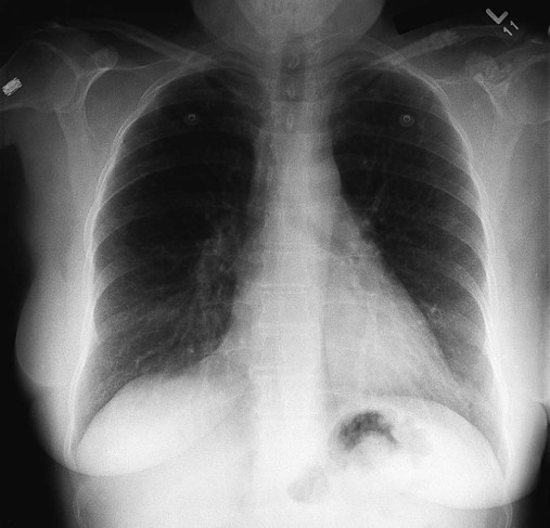
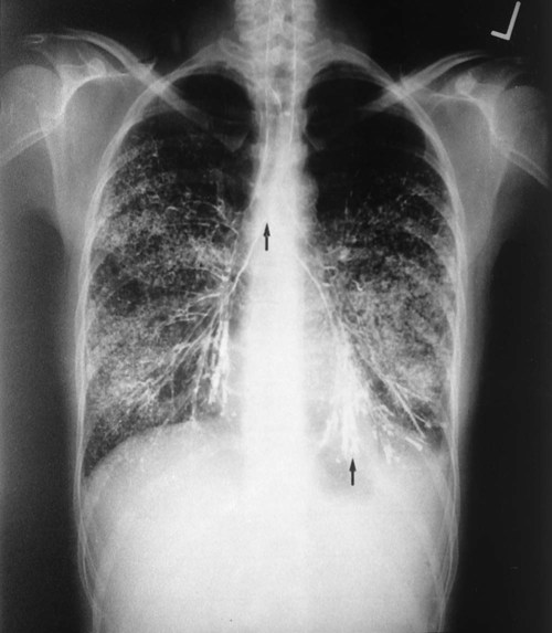
The x-ray examination is usually performed with the patient’s lungs in full inspiration to show the lung fields and related structures to their greatest possible extent. At full inspiration the diaphragm is lowered to approximately the level of the ninth to eleventh ribs posteriorly (Figure 7-1). For certain clinical conditions, radiographs are sometimes taken at the end of both inspiration and expiration. For example, in patients with obstructive lung disease an expiratory radiograph may be made to evaluate diaphragmatic excursion and the symmetry or asymmetry of such excursion (Figure 7-2).
Anteroposterior Radiograph
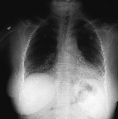
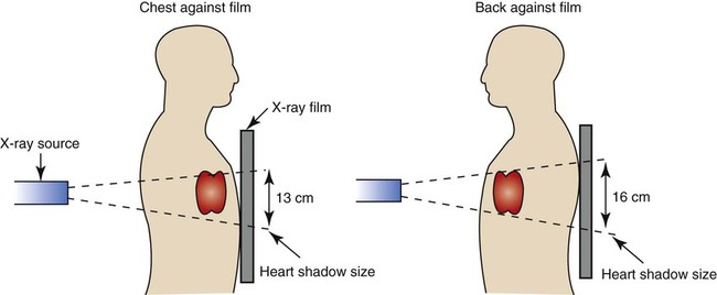
Compared with the PA radiograph, the AP radiograph has a number of disadvantages. For example, the heart and superior portion of the mediastinum are significantly magnified in the AP radiograph. This is because the heart is positioned in front of the thorax as the x-ray beams pass through the chest in the anterior-to-posterior direction, causing the image of the heart to be enlarged (Figure 7-3).
The AP radiograph also often has less resolution and more distortion. Because the patient is often unable to sustain a maximal inspiration, the lower lung lobes frequently appear hazy, erroneously suggesting pulmonary congestion or pleural effusion. Finally, because the AP radiograph is often taken in the intensive care unit, extraneous shadows, such as those produced by ventilator tubing and indwelling lines, are often present (Figure 7-4).
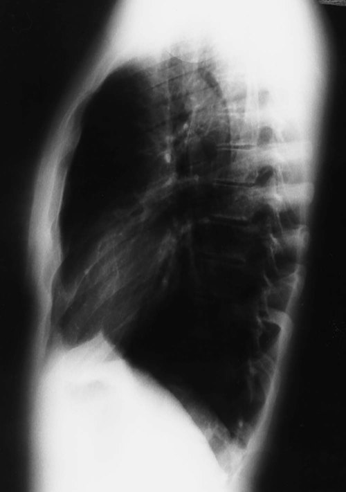
Lateral Radiograph
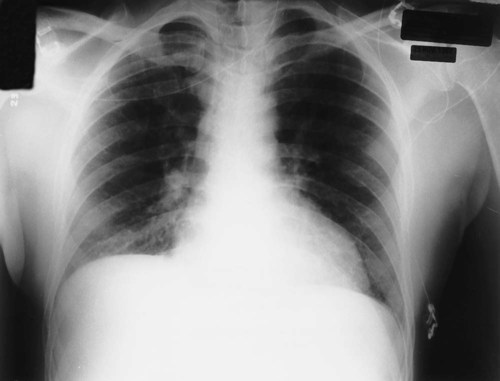
To view the right lung and heart, the patient’s right side is placed against the cassette. To view the left lung and heart, the patient’s left side is placed against the cassette. Therefore a right lateral radiograph would be selected to view a density or lesion that is known to be in the right lung. If neither lung is of particular interest, a left lateral radiograph is usually selected to reduce the magnification of the heart. The lateral radiograph provides a view of the structures behind the heart and diaphragmatic dome. It also can be combined with the PA radiograph to give the respiratory care provider a three-dimensional view of the structures or of any abnormal densities (Figure 7-5).
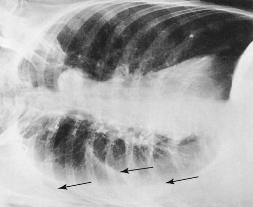
Lateral Decubitus Radiograph
The lateral decubitus radiograph is useful in the diagnosis of a suspected or known fluid accumulation in the pleural space (pleural effusion) that is not easily seen in the PA radiograph. A pleural effusion, which is usually more thinly spread out over the diaphragm in the upright position, collects in the gravity-dependent areas while the patient is in the lateral decubitus position, allowing the fluid to be more readily seen (Figure 7-6).
Inspecting the Chest Radiograph
Before the respiratory care practitioner can effectively identify abnormalities on a chest radiograph, he or she must be able to recognize the normal anatomic structures. Figure 7-7 represents a normal PA chest radiograph with identification of important anatomic landmarks. Figure 7-8 labels the anatomic structures seen on a lateral chest radiograph.
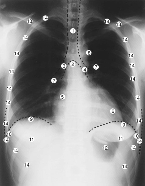
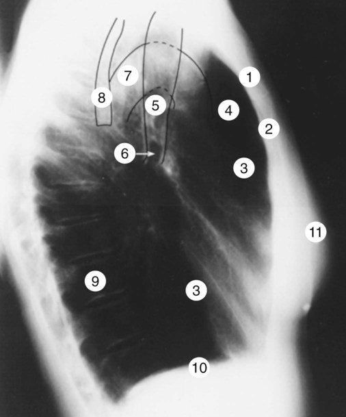
Table 7-1 lists some of the more important radiologic terms used to describe abnormal lung findings.
Table 7-1
| Term | Definition |
| Air cyst | A thin-walled radiolucent area surrounded by normal lung tissue |
| Bleb | A superficial air cyst protruding into the pleura; also called bulla |
| Bronchogram | An outline of air-containing bronchi beyond the normal point of visibility. An air bronchogram develops as a result of an infiltration or consolidation that surrounds the bronchi, producing a contrasting air column on the radiograph—that is, the bronchi appear as dark tubes surrounded by a white area produced by the infiltration or consolidation |
| Bulla | A large, thin-walled radiolucent area surrounded by normal lung tissue |
| Cavity | A radiolucent (dark) area surrounded by dense tissue (white). A cavity is the hallmark of a lung abscess. A fluid level may be seen inside a cavity |
| Consolidation | The act of becoming solid; commonly used to describe the solidification of the lung caused by a pathologic engorgement of the alveoli, as occurs in acute pneumonia |
| Homogeneous density | Refers to a uniformly dense lesion (white area); commonly used to describe solid tumors, fluid-containing cavities, or fluid in the pleural space |
| Honeycombing | A coarse reticular (netlike) density commonly seen in pneumoconiosis |
| Infiltrate | Any poorly defined radiodensity (white area); commonly used to describe an inflammatory lesion |
| Interstitial density | A density caused by interstitial thickening |
| Lesion | Any pathologic or traumatic alteration of tissue or loss of function of a part |
| Opacity | State of being opaque (white); an opaque area or spot; impervious to light rays, or by extension, X-rays; opposite of translucent or radiolucent |
| Pleural density | A radiodensity caused by fluid, tumor, inflammation, or scarring |
| Pulmonary mass | A lesion in the lung that is 6 cm or more in diameter; commonly used to describe a pulmonary tumor |
| Pulmonary nodule | A lesion in the lung that is less than 6 cm in diameter and composed of dense tissue; also called a solitary pulmonary nodule or “coin” lesion because of its rounded, coinlike appearance |
| Radiodensity | Dense areas that appear white on the radiograph; the opposite of radiolucency |
| Radiolucency | The state of being radiolucent; the property of being partly or wholly permeable to X-rays; commonly used to describe darker areas on a radiograph such as an emphysematous lung or a pneumothorax |
| Translucent | Permitting the passage of light; commonly used to describe darker areas of the radiograph |
Technical Quality of the Radiograph
Third, the level of inspiration at the moment the radiograph was taken should be evaluated. At full inspiration the diaphragmatic domes should be at the level of the ninth to eleventh ribs posteriorly. On radiographs taken during expiration, the lungs appear denser, the diaphragm is elevated, and the heart appears wider and enlarged (see Figure 7-2).
Sequence of Examination
Trachea
On the PA projection the trachea should appear as a translucent column overlying the vertebral column. The diameter of the bronchi progressively tapers a short distance beyond the carina and then disappears (see Figure 7-7). A number of clinical conditions can cause the trachea to shift from its normal position. For example, fluid or gas accumulation in the pleural space causes the trachea to shift away from the affected area. Lung collapse or fibrosis usually causes the trachea to shift toward the affected area. The trachea also may be displaced by tumors of the upper lung regions.
Anatomic structures in the chest (e.g., the trachea) move out of their normal position because they are either pushed or pulled in a given direction. In other words, they may be moved up or down or from side to side by lesions pulling or pushing in that direction. Table 7-2 lists examples of factors that push or pull the trachea out of its normal position in the chest radiograph.
Table 7-2
| Structure | Examples of Abnormal Position | Lesion |
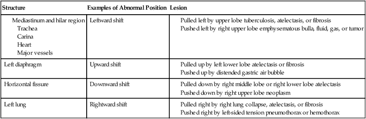
Heart
On the PA projection the ratio of the width of the heart to the thorax (the cardiothoracic ratio) is normally less than 1 : 2. A small portion of the heart should be visible on the right side of the vertebral column. Two bulges should be seen on the right border of the heart. The upper bulge is the superior vena cava; the lower bulge is the right atrium. Three bulges are normally seen on the left side of the heart. The superior bulge is the aorta, the middle bulge is the main pulmonary artery, and the inferior bulge is the left ventricle (see Figure 7-7). See Table 7-2 for examples of factors that push or pull the heart out of its normal position in the chest radiograph.
Hilar Region
The right and left hilar regions should be evaluated for change in size or position. Normally the left hilum is about 2 cm higher than the right (see Figure 7-7). An increased density of the hilar region may indicate engorgement of hilar vessels caused by increased pulmonary vascular resistance. Vertical displacement of the hilum suggests volume loss from one or more upper lobes of the lung on the affected side. In infectious lung disorders such as histoplasmosis or tuberculosis the lymph nodes around the hilar region are often enlarged, calcified, or both. Malignant pulmonary lesions, including hilar malignant lymphadenopathy, also may be seen. See Table 7-2 for additional factors that push or pull the hilar region out of its normal position in the chest radiograph.
Lung Parenchyma (Tissue)
The lungs parenchyma should be examined systematically from top to bottom, one lung compared with the other. Normally, tissue markings can be seen throughout the lungs (see Figure 7-7). The absence of tissue markings may suggest a pneumothorax, recent pneumonectomy, or chronic obstructive lung disease (e.g., emphysema) or may be the result of an overexposed radiograph. An excessive amount of tissue markings may indicate fibrosis, interstitial or alveolar edema, lung compression, or an underexposed radiograph. The periphery of the lung fields should be inspected for abnormalities that obscure the lung’s interface with the pleural space, mediastinum, or diaphragm. See Table 7-2 for additional examples of factors that push or pull the lung tissue out of its normal position in the chest radiograph.
Pleura
The peripheral borders of the lungs should be examined for pleural thickening, presence of fluid (pleural effusion) or air (pneumothorax) in the pleural space, or mass lesions (see Figure 7-7). The costophrenic angles should be inspected. Blunting of the costophrenic angle suggests the presence of fluid. A lateral decubitus radiograph may be required to confirm the presence of fluid (see Figure 7-6).
Diaphragms
Both the right and left hemidiaphragms should have an upwardly convex, dome-shaped contour. The right and left costophrenic angles should be clear. Normally, the right diaphragm is about 2 cm higher than the left because of the liver below it (see Figure 7-7). Chronic obstructive pulmonary diseases (e.g., emphysema) and diseases that cause gas or fluid to accumulate in the pleural space flatten and depress the normal curvature of the diaphragm. Abnormal elevation of one diaphragm may result from excessive gas in the stomach, collapse of the middle or lower lobe on the affected side, pulmonary infection at the lung bases, phrenic nerve damage, or spinal curvature. See Table 7-2 for additional examples of factors that push or pull the diaphragm out of its normal position in the chest radiograph.
Bony Thorax
The ribs, vertebrae, clavicles, sternum, and scapulae should be inspected. The intercostal spaces should be symmetric and equal over each lung field (see Figure 7-7). Intercostal spaces that are too close together suggest a loss of muscle tone, commonly seen in patients with paralysis involving one side of the chest. In chronic obstructive pulmonary disease the intercostal spaces are generally far apart because of alveolar hyperinflation. Finally, the ribs should be inspected for deformities or fractures. If a rib fracture is suspected but not seen on the standard chest radiograph, a special rib series (radiographs that focus on the ribs) may be necessary.
Extrathoracic Soft Tissues
The soft tissue external to the bony thorax should be closely inspected. If the patient is a female, the outer boundaries of the breast shadows should be identified (see Figure 7-7). If the patient has undergone a mastectomy, there will be a relative hyperlucency on the side of the mastectomy. Large breasts can create a significant amount of haziness over the lower lung fields, giving the false appearance of pneumonia or pulmonary congestion. Although nipple shadows are easily identified when they are bilaterally symmetric, one may become less visible when the patient is slightly rotated. The other nipple then appears abnormally opaque and may be mistaken for a pulmonary nodule. After a tracheostomy or pneumothorax, subcutaneous air bubbles (called subcutaneous emphysema) often form in the soft tissue, especially if the patient is on a positive-pressure ventilator.
Computed Tomography
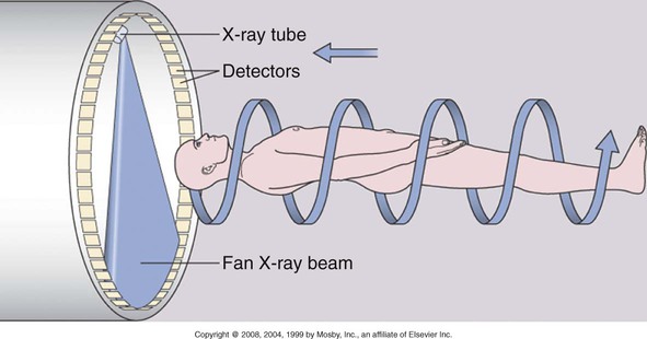
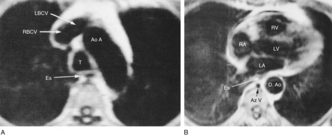
The same basic principles used in film radiography apply to computed tomography (CT) scanning—namely the absorption of x-rays by tissues that contain anatomic structures and organs of different atomic number. A CT scan provides a series of cross-sectional (transverse) pictures (called tomograms) of the structures within the body at numerous levels. The procedure is painless and noninvasive and requires no special preparation. The patient simply lies on the examination table, and this moves the patient through the opening of the CT scanner. The major components of a CT scanner are (1) an x-ray tube, which rotates in a continuous 360-degree motion around the patient to image the body in cross-sectional slices; (2) an array of x-ray detectors opposite the x-ray tube, which record the x-rays that pass through the body; and (3) a computer, which converts the different x-ray absorption levels to cross-sectional images based on the density of the structures being scanned. This cross-sectional slice is called an axial view, or computerized axial tomogram (Figure 7-9).
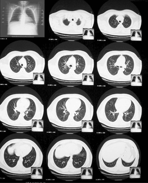
The resolution of a CT scan can be adjusted to primarily view (1) lung tissue—commonly called a lung window CT scan—or (2) bone and mediastinal structures—commonly called a mediastinal window CT scan. In a mediastinal window CT scan, the lung tissue is overexposed and appears mostly black; the bones and mediastinal organs appear mostly white. Figure 7-10 provides an overview of a normal lung window CT scan. Figure 7-11 shows a close-up of one “slice” of a normal lung window CT scan. Figure 7-12 provides a close-up view of one slice of a normal mediastinal window CT scan.
Positron Emission Tomography
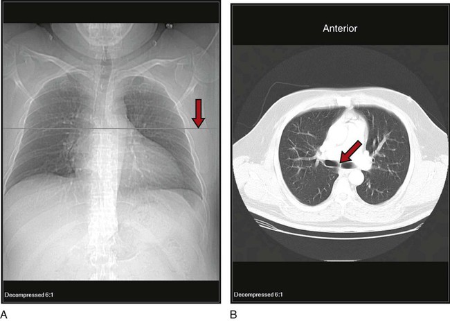
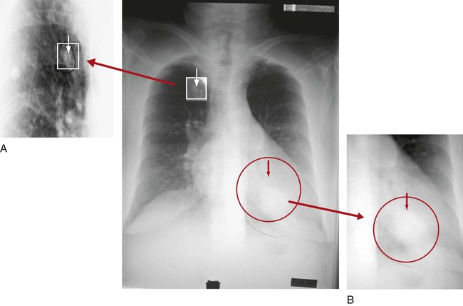
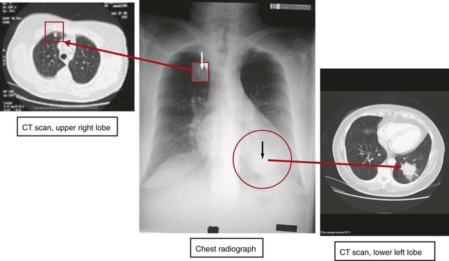
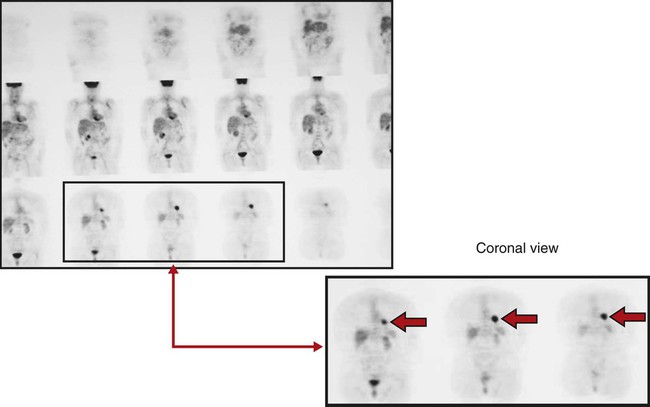
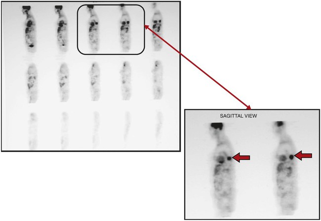
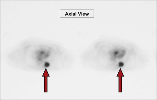
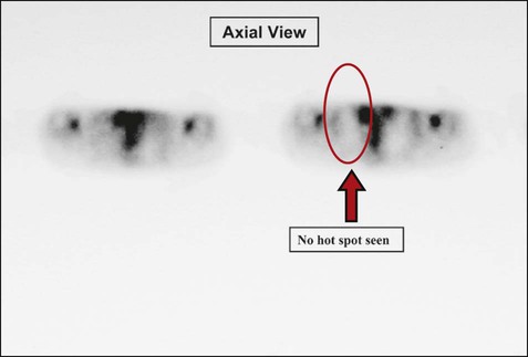
Clinically, a PET scan is an excellent tool to rule out suspicious findings (i.e., a possible cancerous area) that are identified on either the chest radiograph or CT scan. For example, Figure 7-13 shows a chest radiograph that identifies two suspicious findings—one small nodule in the right upper lung lobe and a larger density in the left lower lung lobe, just behind the heart. Figure 7-14 shows two CT scans that also identify the two suspicious findings and their precise location. Figures 7-15, 7-16 and 7-17 show PET scans that all confirm a hot spot (likely cancer) in the lower left lobe. However, the PET scan shown in Figure 7-18 confirms that the nodule in the right upper lobe is benign (i.e., no hot spot noted).
Positron Emission Tomography and Computed Tomography Scan
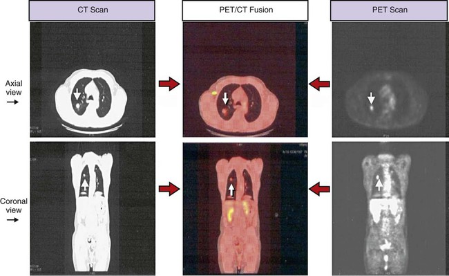
Technology has now been developed that allows both the PET scan and the CT scan to be merged together and performed at the same time. The image produced is called a positron emission tomography and computed tomography scan (PET/CT scan) scan (also known as a PET/CT fusion). The PET/CT scan provides an image far superior to that afforded by either technology independently. When combined, the CT scan provides the anatomic detail regarding the precise size, shape, and location of the tumor, and the PET scan provides the metabolic activity of the tumor or mass. The PET/CT image provides excellent image quality and high sensitivity and specificity in detecting malignant lesions in the chest. Figure 7-19 shows a PET/CT scan alongside a CT scan and a PET scan; all the images show the same malignant nodule in the right upper lung lobe.
Magnetic Resonance Imaging
MRI uses magnetic resonance as its source of energy to take cross-sectional (transverse, sagittal, or coronal) images of the body. It uses no ionizing radiation. The patient is placed in the cylindric imager, and the body part in question is exposed to a magnetic field and radiowave transmission. The MRI produces a high-contrast image that can detect subtle lesions (Figure 7-20).
Pulmonary Angiography
Pulmonary angiography is useful in identifying pulmonary emboli or arteriovenous malformations. It involves the injection of a radiopaque contrast medium through a catheter that has been passed through the right side of the heart and into the pulmonary artery. The injection of the contrast material into the pulmonary circulation is followed by rapid serial pulmonary angiograms. The pulmonary vessels are filled with radiopaque contrast material and therefore appear white. Figure 7-21 shows an abnormal angiogram in which the major blood vessels appear absent distal to pulmonary emboli in the left lung.
Ventilation-Perfusion Scan
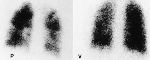
The perfusion scan is supplemented with a ventilation scan. During the ventilation scan the patient breathes a radioactive gas such as xenon-133 from a closed-circuit spirometer. A gamma camera is used to create a picture of the gas distribution throughout the lungs. A normal ventilation scan shows a uniform distribution of the gas, with the dark areas reflecting the presence of the radioactive gas and therefore good ventilation. White or light areas represent decreased or complete absence of ventilation. See Figure 7-22 for an abnormal perfusion scan and a normal ventilation scan of a patient with a severe pulmonary embolism. An abnormal ventilation scan also may be caused by airway obstruction (e.g., mucous plug or bronchospasm), loss of alveolar elasticity (e.g., emphysema), alveolar consolidation, or pulmonary edema.
Bronchography
Bronchography entails the instillation of a radiopaque material into the lumen of the tracheobronchial tree. A chest radiograph is then taken, providing a film called a bronchogram. The contrast material provides a clear outline of the trachea, carina, right and left main stem bronchi, and segmental bronchi. Bronchography is occasionally used to diagnose bronchogenic carcinoma and determine the presence or extent of bronchiectasis (Figure 7-23). CT of the chest has largely replaced this technique.
[/level-membership-for-pulmolory-and-respiratory-category][not-level-membership-for-pulmolory-and-respiratory-category]
Radiologic Examination of the Chest
After reading this chapter, you will be able to:
• Describe the fundamentals of radiography.
• Differentiate among the following standard positions and techniques of chest radiography:
• Lateral decubitus radiograph
• Define the following radiologic terms commonly used during inspection of the chest radiograph:
• Describe the three steps to evaluate technical quality of the radiograph.
• Describe the sequence of examination, and include the following:
• Describe the diagnostic values of the following radiologic procedures:
• Positron emission tomography (PET)
• Positron emission tomography and computed tomography scan (PET/CT scan)
• Magnetic resonance imaging (MRI)
• Define key terms and complete self-assessment questions at the end of the chapter and on Evolve.
Standard Positions and Techniques of Chest Radiography
Posteroanterior Radiograph
The x-ray examination is usually performed with the patient’s lungs in full inspiration to show the lung fields and related structures to their greatest possible extent. At full inspiration the diaphragm is lowered to approximately the level of the ninth to eleventh ribs posteriorly (Figure 7-1). For certain clinical conditions, radiographs are sometimes taken at the end of both inspiration and expiration. For example, in patients with obstructive lung disease an expiratory radiograph may be made to evaluate diaphragmatic excursion and the symmetry or asymmetry of such excursion (Figure 7-2).
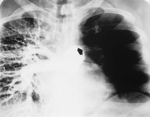
Anteroposterior Radiograph
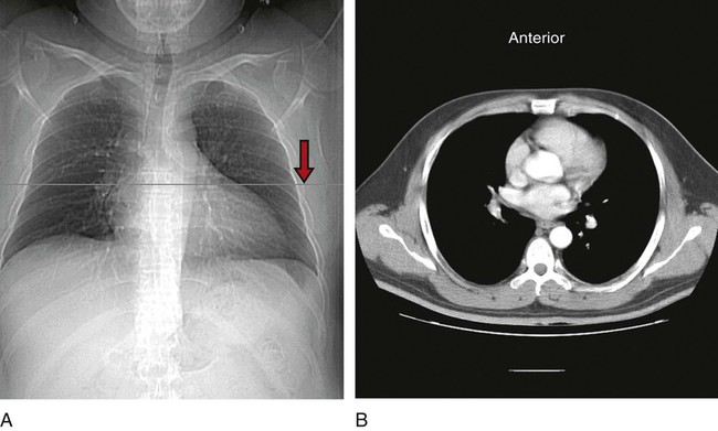
Compared with the PA radiograph, the AP radiograph has a number of disadvantages. For example, the heart and superior portion of the mediastinum are significantly magnified in the AP radiograph. This is because the heart is positioned in front of the thorax as the x-ray beams pass through the chest in the anterior-to-posterior direction, causing the image of the heart to be enlarged (Figure 7-3).
The AP radiograph also often has less resolution and more distortion. Because the patient is often unable to sustain a maximal inspiration, the lower lung lobes frequently appear hazy, erroneously suggesting pulmonary congestion or pleural effusion. Finally, because the AP radiograph is often taken in the intensive care unit, extraneous shadows, such as those produced by ventilator tubing and indwelling lines, are often present (Figure 7-4).
Lateral Radiograph
To view the right lung and heart, the patient’s right side is placed against the cassette. To view the left lung and heart, the patient’s left side is placed against the cassette. Therefore a right lateral radiograph would be selected to view a density or lesion that is known to be in the right lung. If neither lung is of particular interest, a left lateral radiograph is usually selected to reduce the magnification of the heart. The lateral radiograph provides a view of the structures behind the heart and diaphragmatic dome. It also can be combined with the PA radiograph to give the respiratory care provider a three-dimensional view of the structures or of any abnormal densities (Figure 7-5).
Lateral Decubitus Radiograph
The lateral decubitus radiograph is useful in the diagnosis of a suspected or known fluid accumulation in the pleural space (pleural effusion) that is not easily seen in the PA radiograph. A pleural effusion, which is usually more thinly spread out over the diaphragm in the upright position, collects in the gravity-dependent areas while the patient is in the lateral decubitus position, allowing the fluid to be more readily seen (Figure 7-6).
Inspecting the Chest Radiograph
Before the respiratory care practitioner can effectively identify abnormalities on a chest radiograph, he or she must be able to recognize the normal anatomic structures. Figure 7-7 represents a normal PA chest radiograph with identification of important anatomic landmarks. Figure 7-8 labels the anatomic structures seen on a lateral chest radiograph.
[/not-level-membership-for-pulmolory-and-respiratory-category]
