Chapter 18 Radiographic anatomy
Lateral views of the lumbar spine are relatively simple; few parts are superimposed, but anteroposterior (AP) views are complicated by multiple parts being superimposed. Under those conditions, interpretation is assisted by the use of anatomy by expectation (see Ch. 17). The reader should expect what should be present, and then determine if what they expect is, indeed, evident on the image.
Lateral views
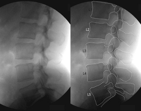
When viewing a lateral radiograph of the lumbar spine (Fig. 18.1), the reader should expect to see the osseous anatomy evident in a lateral view of an anatomical specimen (as described in Ch. 17) (Fig. 18.2). Soft tissues, such as the ligamentum flavum and spinal nerves will not be evident, but the vertebral bodies and posterior elements will be evident. The intervertebral discs will not be evident; they will appear as spaces between the vertebral bodies.
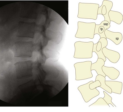
On the radiograph, select a vertebra image that is the least obscure: typically that of L3. The superior, anterior and inferior margins of the vertebral body should be evident, as they are not obscured by any overlying shadows. Trace those margins (Fig. 18.3). Continue the tracing onto the posterior margin until that margin meets the root of the pedicle. Continue the tracing onto the pedicle. Thereafter, the tracing may become difficult, but the reader is helped by looking for what they expect to see. Based on what they know to be the anatomy of the superior articular process (Fig. 18.2), the reader should expect that, from the posterior superior corner of the pedicle, the superior articular process would project dorsally and cephalad, like the rounded head of a small mushroom. Therefore, regardless of any other lines that might be evident, the reader should look to see if any lines correspond with such a rounded projection. From the superior border of the pedicle, the tracing should continue to circumscribe this rounded projection (Fig. 18.3).

Similarly, the reader should expect that, from the posterior inferior corner of the pedicle, a narrow lamina would project caudally and slightly dorsally, and eventually expand into a rounded mass that is the inferior articular process. As before, other lines should be disregarded, and only those that conform to this expectation should be traced to complete the inferior articular process (Fig. 18.3).
The reader should expect that the transverse process projects as an elliptical shadow at the junction between the pedicle and the superior articular process. Finding such an elliptical shadow locates the transverse process (Fig. 18.3).
For the spinous process, the reader should expect a projection, with the profile of the blade of an axe, arising from the back of the lamina. Finding and tracing the margin of the spinous process completes the identification of the posterior elements (Fig. 18.3).
Having accomplished this tracing of the L3 vertebra, the reader can repeat the process for all other vertebrae, until all lumbar vertebrae have been traced (Fig. 18.4). In this process, two details arise. Firstly, unlike those of typical lumbar levels, the transverse process of L5 has a large base that flows onto the pedicle and vertebral body of L5. Secondly, at all segmental levels, the superior articular processes cover the inferior articular processes of the vertebra above. The latter introduces a complexity.
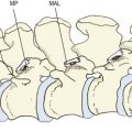
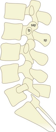
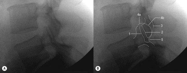
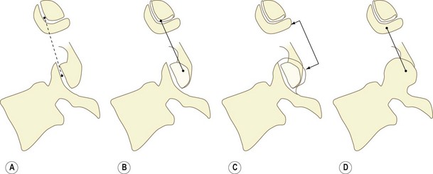
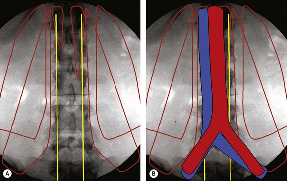
Because bones behave as if they are transparent under X-ray, multiple markings can appear in the zygapophysial joints. These markings may create the illusion that the joint space projects laterally (Fig. 18.5). This appearance arises when C-shaped or J-shaped joints are viewed from the side. What appear to be the joint margins in a radiograph (lines 1 and 2 in Fig. 18.5) are only the articular margins of the ventral portion of the joint (Fig. 18.6A); but this is not the entire joint. The inferior articular process also presents the remainder of its joint surface laterally (Fig. 18.6B). This surface will be covered laterally by the remainder of the superior articular process (Fig. 18.6C), and in an intact anatomical specimen the inferior articular process will no longer be visible (Fig. 18.6D). As a result of this arrangement, line 2 in Figure 18.5B is continuous with the rest of the inferior articular process (line 3); and lines 4a and 4b form the outer margin of the superior articular process, which becomes continuous with the lamina as line 5. Having identified the silhouettes of all the parts of the lumbar vertebrae, the reader should then be able to imagine the location of related structures that are not visible with X-rays.
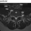
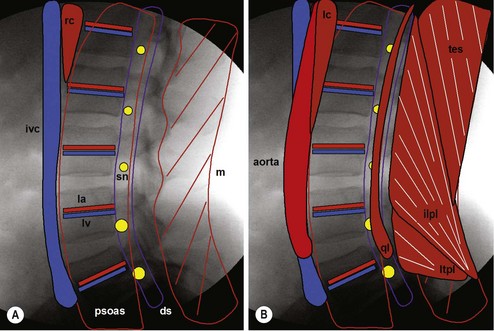
In the region of the vertebral bodies, the reader should expect: the dural sac behind the vertebral bodies; the spinal nerves in the intervertebral foramina; and the psoas major clamping the lumbar arteries and lumbar veins against the vertebral bodies (Fig. 18.7A). Anterior, towards the right, the reader should expect the right crus and the inferior vena cava (Fig. 18.7A). Posteriorly, behind the laminae and against the spinous processes, they should expect the multifidus muscle, with its fibres passing dorsally and cephalad (Fig. 18.7A). Superimposed on these structures the reader should expect various additional structures (Fig. 18.7B). Anteriorly, to the left of the inferior vena cava, they should expect the aorta and left crus. Centrally, they should expect the quadratus lumborum behind and lateral to the psoas. Posteriorly, they should expect the fibres of the lumbar and lower thoracic erector spinae, lateral to the multifidus. The fibres of these muscles would run cephalad and ventrally.
Anterior (or posterior) view
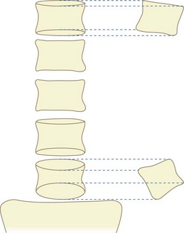
In anterior or posterior views, because of the lumbar lordosis, not every vertebral body will be seen as horizontal. Upper vertebrae will be tilted to face cephalad and forwards, while lower vertebrae will be tilted caudad and forwards. As a result, whereas the superior and inferior borders of middle lumbar vertebral bodies will present as transverse lines, those of upper and lower vertebrae will present as ellipses (Fig. 18.8). Because upper lumbar vertebrae are tilted upwards, the anterior margins of their superior and inferior surfaces lie higher than the posterior margins. Therefore, the more cephalad margin of the ellipse corresponds with the anterior margin of the body, while the more caudad margin corresponds with the posterior margin (Fig. 18.8). For lower vertebral bodies, the opposite applies. These vertebrae are tilted downwards, and the anterior margins of their superior and inferior surfaces are lower than the respective posterior margins. Therefore, the more cephalad margin of the ellipse corresponds with the posterior margin of the vertebral body, while the more caudad margin corresponds with the anterior margin (Fig. 18.8).
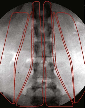
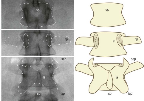
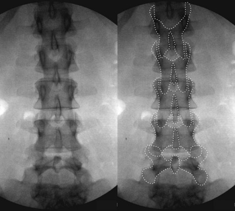
Readers should expect a rectangular shadow, with a scalloped waist, that corresponds to the vertebral body (Fig. 18.9). They should expect a pair of vertical ellipses that correspond to the pedicles, from which the transverse processes project laterally (Fig. 18.9). Finally, they should expect the rectangular plates of the laminae, from whose corners project the superior articular processes and inferior articular processes, and from the centre of which projects the spinous process (Fig. 18.9). Reading an anterior view then becomes an exercise of identifying these various lines for each vertebra, and adjusting for the tilt of the vertebrae in the lumbar lordosis. An efficient protocol follows.
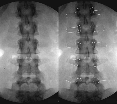
It is perhaps easiest to recognise first the pedicles and transverse processes, for these are least affected by tilt. Common radiologic teaching is to look for pedicles as if they were the ‘eyes’ of five vertebrae looking forwards (Fig. 18.10). The transverse processes should be evident as rectangular bars projecting laterally from the pedicles.
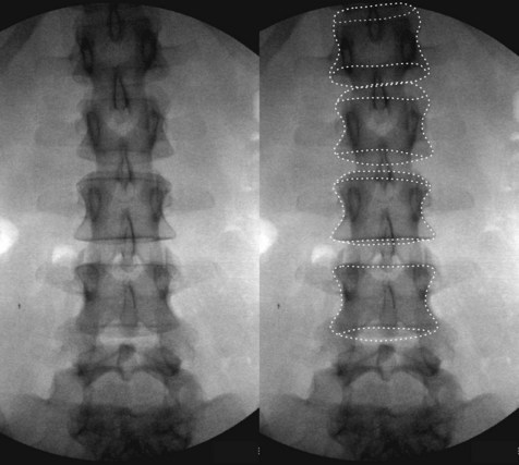
Next, the bodies of the typical lumbar vertebrae can be found and traced. Adjustments will need to be made for superior and inferior surfaces appearing as ellipses (Fig. 18.11). In some cases, the ellipses of superior surfaces may assume the appearance of muffin tops. In tracing a given vertebral body, it is perhaps best to find the inferior corners, and join them with the inferior surface or its ellipse. From each corner, trace the lateral margin cephalad, expecting that it will assume the shape of the scalloped waist of the vertebral body; and in most instances the lateral margin will run tangential, or near, to the lateral margin of the pedicle. The superior corners may be difficult to discern amongst the shadows of the pedicle and superior articular process. The distinguishing features of a superior corner are that it is the only marking, in that region, that assumes a curved, right-angle bend, and which is simultaneously continuous with the lateral margin and with the superior margin. The latter will be the only transversely running line, or ellipse, that passes medially.
In the example shown in Figure 18.11, the vertebral body of L5 is difficult to discern. This arises because the vertebra is severely tilted into lordosis, so much so that its vertebral body is below the level of most of its posterior elements. Also, the vertebral body itself is wedge-shaped. As a result, it does not present a rectangular outline. Largely, the vertebral body presents its inferior surface. Consequently, inferior corners are not evident. However, on the right of the radiograph, a superior corner is evident, and to a lesser extent a superior corner is evident, symmetrically, on the left (Fig. 18.12). From each of these corners, a scalloped margin of the lateral surface of the vertebral body is evident. Between the lower ends of these lateral margins, a broad ellipse is faintly present, which represents the inferior surface (Fig. 18.12). Between the superior corners, a dark transverse line is evident, joining the two corners, which corresponds to part of the superior surface. Otherwise, the remainder of the superior surface is faintly evident as a muffin top projecting cephalad, in a curve parallel to the posterior curvature of the inferior surface of L4 (Fig. 18.12). Once the vertebral body has been outlined, its steep inclination becomes evident.
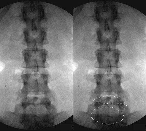
Figure 18.12 A pair of anteroposterior radiographs of the lumbar spine. On the right, the vertebral body of L5 has been outlined.
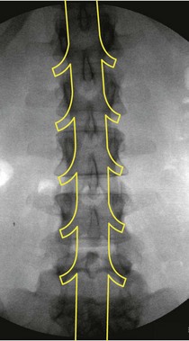
The final step in recognising the radiograph is to trace the posterior elements. A suitable starting point can be the articular margins of a zygapophysial joint where one is evident. Straight, vertical lines will correspond to the articular surfaces (Fig. 18.13). From these straight lines, the respective curvatures of the superior and inferior articular processes can be traced. The convexity of the outer margin of the superior articular process will curve medially and inferiorly, across the pedicle, to become continuous with the lateral margin of the lamina (Fig. 18.13). A confirmatory feature is that, typically, the inferior margin of the transverse process flows seamlessly into the lateral margin of the lamina, opposite the inferolateral corner of the pedicle. The curvature of the inferior articular process continues upwards to become the inferior margin of the lamina (Fig. 18.13). The superior margin of the lamina is usually clearly evident towards the midline. Laterally, however, the superior margin is obscured by the inferior articular process, and its continuity with the superior articular process cannot be defined with certainty.
At segments where joint spaces and articular margins are not evident, the reader should recognise that they are looking at zygapophysial joints that face coronally. At these sites, the opposing – and, therefore, overlapping – inferior and superior articular processes will take on a rounded appearance, instead of presenting sharp corners at the superior or inferior end of the joint (Fig. 18.13).
Having established the osseous anatomy of the lumbar spine, readers should then be prepared to imagine the location of the related soft tissues. Behind the lumbar vertebral bodies will run the dural sac and its contents, with the lumbar spinal nerves and their dural sleeves curving around the pedicles (Fig. 18.14).
Anterior to the vertebral column, the reader should expect the left crus and right crus, at upper lumbar levels, and the lumbar sympathetic trunks throughout the length of the column (Fig. 18.15A). Lateral to the vertebral column they should expect the quadratus lumborum covered by the psoas major (Fig. 18.15A). Subsequently, the reader should expect the inferior vena cava and aorta to cover the vertebral bodies, as far as L5 and L4, respectively (Fig. 18.15B).
Posterior to the vertebral column, the reader should expect the multifidus covering the laminae, the longissimus thoracic pars lumborum aiming for the accessory processes, and the iliocostalis lumborum pars lumborum aiming for the tips of the transverse processes (Fig. 18.16).