[level-membership-for-radiology-category]
Quality Acceptance Testing within Digital Projection Imaging
Objectives
On completion of this chapter, you should be able to:
• Discuss total quality management and its uses in digital projection imaging.
• Explain the importance of establishing a repeat analysis database with digital projection imaging.
• Become familiar with problem reporting responsibilities.
• Recognize the quality management (QM) and QC activities to be performed by the radiation physicist.
Key Terms
Total quality management (TQM)
Preventative maintenance (PM)
Total Quality Management
Maintenance of equipment, image acquisition, and processing standards are quality control issues that fit into the concept of total quality management (TQM) or continuous quality improvement (CQI), as discussed in Chapter 11. The overall efficiency and effectiveness of imaging systems are evaluated beyond the mechanics of producing radiographic images. This chapter introduces the concept of whole system evaluation, considering image acquisition, processing, and evaluation issues as well as examination repeat analysis, communication issues, and system problem identification.
Quality Control Standards
The American College of Radiology requires compliance with standards of practice to assure quality in any imaging system. Three general areas define digital image quality: contrast, resolution, and noise. These areas must be monitored to avoid unnecessary repeat examinations and overexposure to patients and staff. There are a number of system tests that must be performed by service personnel and/or radiologic technologists and radiation physicists. With the increased sophistication of digital radiographic equipment, it is critical that these tests be performed in a consistent and thorough manner.
The American Association of Physicists in Medicine publishes the following documents based on work accomplished by task groups:
• Task Group 116—An Exposure Indicator for Digital Radiography
• Task Group 150—Acceptance Testing and Quality Control of Digital Imaging Units
The following sections are in no way an exhaustive list of activities that should be performed. The manufacturer’s suggested list of systems tests should be performed as indicated in the equipment and service manuals.
Quality Control Schedules and Responsibilities
The radiologic technologist is the first line of defense in preventing, recognizing, and reporting quality control (QC) issues. Quality control is defined as a comprehensive set of activities designed to monitor and maintain a system or piece of equipment. The complicated and delicate nature of digital equipment necessitates frequent and consistent oversight to avoid image errors and unnecessary patient exposure. The following is a suggested schedule for proper digital system maintenance.
Technologist Responsibilities
Daily (Box 12-1)
• General system inspection including the following:
• Laser-generated sensitometry strip; film densities measurement
• Dust particles, scratches, mechanical friction marks
• Send images to picture archiving and communication system (PACS)
• Verification of digital interfaces and network transmission
Weekly (Box 12-2)
• Equipment manufacturers should provide lists of appropriate system tests to be performed by the technologists. This type of testing may be performed by a designated QC technologist rather than by each individual technologist. All problems must be recorded and reported immediately. Examples of this type of test include the following:
• Image acquisition testing with phantoms
• Cassette integrity testing with special, standardized cassettes
• Clean the air intakes on the image plate reader.
Monthly (Box 12-3)
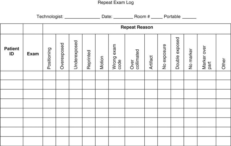
• It is critical that repeat exposures are identified so that data concerning repeat reason, number of repeats, and the technologist responsible for the repeat can be analyzed. One issue is that whereas digital systems with integrated generator consoles record the milliampere-seconds (mAs) and kilovoltage peak (kVp) values directly on the film, nonintegrated systems do not. In cases where the department does not require manual technologist identification input, it is strongly recommended that a personal repeat rate log be kept by each technologist (see sample in Figure 12-1). This will allow the technologist to see possible trends in exposure, positioning, and procedural errors. For example, if the repeat reason is underexposure, the cause could be poor calibration of the automatic exposure control (AEC), or it could be poor imaging skills. Either way, identification of this trend will allow the technologist to improve imaging procedures and better protect the patient. This can be accomplished to a certain extent with a software program. Many vendors have software to automatically keep repeats in a folder for the QC technologists to review, eliminating the issue of technologists deleting repeat exposure images.
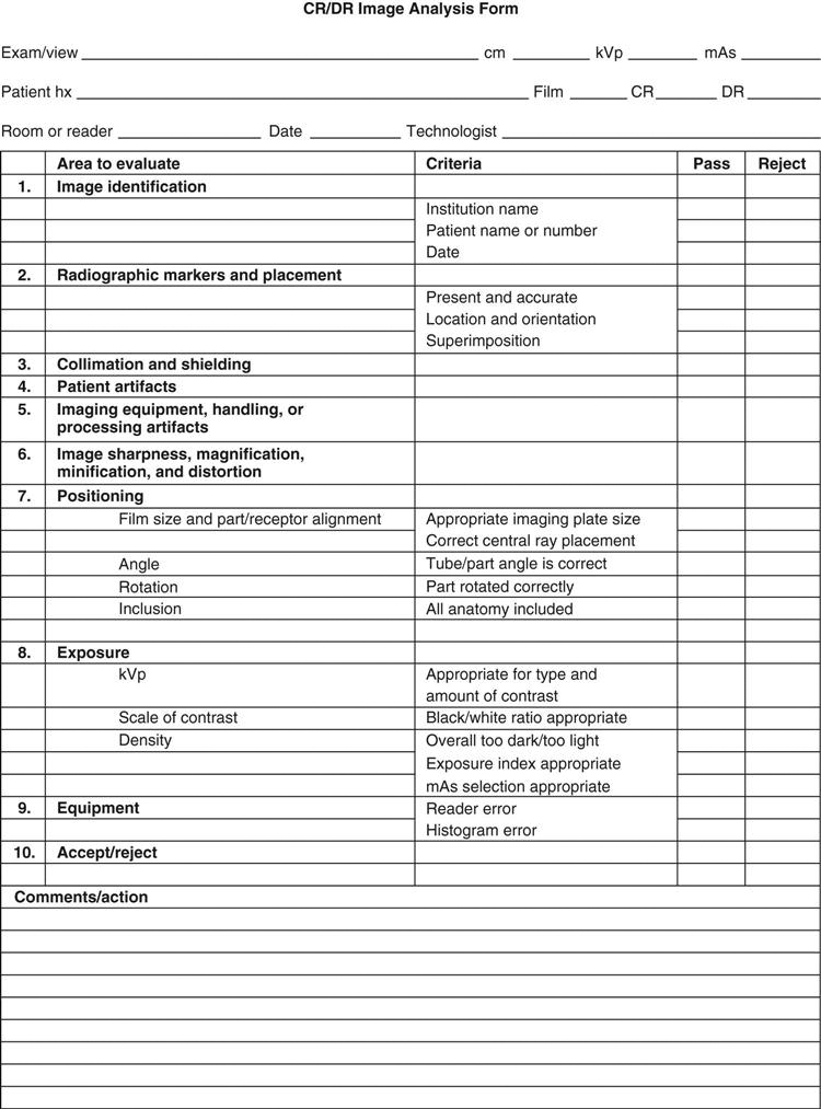
Typically, a technologist is assigned the responsibility of coordinating analysis of images of suboptimal quality. This may be done in concert with a radiation physicist, the purpose being to identify equipment and technologist performance errors (see sample reject analysis form in Figure 12-2). This type of analysis helps determine the following:
Disposal must be handled by a licensed disposal company; no other means of disposal, such as putting it in trash cans, is acceptable. This type of disposal requires an EPA identification number, which is assigned by the state. Be sure to be familiar with disposal regulations.
Service Personnel Responsibilities
Although specific responsibilities will vary from manufacturer to manufacturer and vendor to vendor, generally speaking service personnel have a duty to the consumer to ensure that equipment is being maintained properly. This is accomplished through a program of preventative maintenance that typically takes place semiannually. Preventative maintenance (PM) consists of a series of equipment tests that are performed by a service engineer. This engineer may be employed by the hospital or the equipment manufacturer.
Physicist Responsibilities for PSP Systems
Schedules for physicist review of photostimulable phosphor (PSP) digital imaging systems may vary depending on availability (see Box 12-4). One physicist may handle multiple medical facilities, visiting each one on a weekly or monthly basis. Others may be employed by only one facility and be much more active in determining review procedures. Typical responsibilities include the following:
The standard QC tests for filtration, collimation, focal-spot size, kVp calibration, exposure timer accuracy, exposure linearity, exposure reproducibility, and protective apparel will remain the same, but the American Association of Physicists in Medicine has established a set of QC parameters to be followed for PSP systems in AAPM Report #93. This report details the tests and reports to be performed. Consult the AAPM website for the most up-to-date QC procedures for digital projection radiography systems.
Summary
Chapter Review Questions
1. What organization developed the standards for acceptance testing and quality control of photostimulable storage phosphor (PSP) imaging systems?
a. American College of Radiologists
b. American Society of Radiologic Technologists
c. American Association of Physicists in Medicine
2. Which of the following are daily QC duties of a technologist?
c. Image inspection for artifacts
3. An imaging plate should be erased when it has not been used for an extended period of time.
a. True
b. False
4. Which of the following are weekly QC duties of a technologist?
5. The EPA regulates the disposal of PSP imaging plates.
a. True
b. False
6. The physicist is responsible for performing the preventative maintenance on the digital imaging systems.
a. True
b. False
7. How often does a physicist perform an accuracy test between the exposure indices and the ion chamber?
a. Monthly
b. Quarterly
c. Semiannually
d. Annually
8. Which of the following should not be used to clean the PSP imaging plates?
9. The display monitors should be cleaned on a monthly basis.
a. True
b. False
10. Whose responsibility is it to maintain the quality of digital images?
a. Technologist
b. Radiologist
c. Physicist
[/level-membership-for-radiology-category][not-level-membership-for-radiology-category]
Quality Acceptance Testing within Digital Projection Imaging
Objectives
On completion of this chapter, you should be able to:
• Discuss total quality management and its uses in digital projection imaging.
• Explain the importance of establishing a repeat analysis database with digital projection imaging.
• Become familiar with problem reporting responsibilities.
• Recognize the quality management (QM) and QC activities to be performed by the radiation physicist.
Key Terms
Total quality management (TQM)
Preventative maintenance (PM)
Total Quality Management
Maintenance of equipment, image acquisition, and processing standards are quality control issues that fit into the concept of total quality management (TQM) or continuous quality improvement (CQI), as discussed in Chapter 11. The overall efficiency and effectiveness of imaging systems are evaluated beyond the mechanics of producing radiographic images. This chapter introduces the concept of whole system evaluation, considering image acquisition, processing, and evaluation issues as well as examination repeat analysis, communication issues, and system problem identification.
Quality Control Standards
The American College of Radiology requires compliance with standards of practice to assure quality in any imaging system. Three general areas define digital image quality: contrast, resolution, and noise. These areas must be monitored to avoid unnecessary repeat examinations and overexposure to patients and staff. There are a number of system tests that must be performed by service personnel and/or radiologic technologists and radiation physicists. With the increased sophistication of digital radiographic equipment, it is critical that these tests be performed in a consistent and thorough manner.
The American Association of Physicists in Medicine publishes the following documents based on work accomplished by task groups:
• Task Group 116—An Exposure Indicator for Digital Radiography
• Task Group 150—Acceptance Testing and Quality Control of Digital Imaging Units
The following sections are in no way an exhaustive list of activities that should be performed. The manufacturer’s suggested list of systems tests should be performed as indicated in the equipment and service manuals.
Quality Control Schedules and Responsibilities
The radiologic technologist is the first line of defense in preventing, recognizing, and reporting quality control (QC) issues. Quality control is defined as a comprehensive set of activities designed to monitor and maintain a system or piece of equipment. The complicated and delicate nature of digital equipment necessitates frequent and consistent oversight to avoid image errors and unnecessary patient exposure. The following is a suggested schedule for proper digital system maintenance.
Technologist Responsibilities
Daily (Box 12-1)
• General system inspection including the following:
• Laser-generated sensitometry strip; film densities measurement
• Dust particles, scratches, mechanical friction marks
• Send images to picture archiving and communication system (PACS)
• Verification of digital interfaces and network transmission
Weekly (Box 12-2)
[/not-level-membership-for-radiology-category]
