[level-membership-for-pulmolory-and-respiratory-category]Chapter 11
Pulmonary Function Testing Equipment
1. Describe two types of volume-displacement spirometers.
2. List at least two principles used by flow-sensing spirometers to measure volume.
3. Select a directional breathing valve for a specific testing situation.
4. Identify the types of gas analyzers used for diffusing capacity and dilutional lung volume tests.
5. Describe the function of commonly used gas conditioning devices.
1. Select and set up the basic components of a body plethysmograph.
2. Contrast and compare measurement of oxygen saturation by multiwavelength and pulse oximeters.
3. Identify the measurement principles of pH, Pco2, and Po2 blood gas devices.
4. Describe the important characteristics of an “office” spirometer.
5. Discuss various types of data storage applicable to pulmonary function data.
VOLUME-DISPLACEMENT spirometers
Water-Seal Spirometers
For more than 100 years, the water-seal spirometer was the basic tool used to measure lung volumes and flows. The spirometer consists of a large bell (7–10 L) suspended in a container of water with the open end of the bell below the surface of the water (Figure 11-1, A and B). A breathing circuit inserted into the interior of the bell allows for accurate measurement of gas volumes. The patient breathes into the spirometer, moving the bell up during expiration and down with inspiration. Each spirometer bell has a “bell factor” relating the vertical distance moved to a specific volume (milliliters or liters). For many years, movement of the bell was recorded using a pen to make a tracing on a rotating drum, called a kymograph. Volumes were measured from the kymograph tracing by using paper that incorporated the bell factor for the spirometer. Volumes measured in this way reflect the gas in the spirometer that is at keytermambient temperature, pressure, and saturation (ATPS). These volumes, such as vital capacity (VC), had to be corrected to body temperature, pressure and saturation (BPTS).
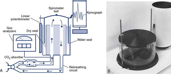
For simple spirometry, a single large-bore tube can be used for both inspiration and expiration. For rebreathing studies, the breathing circuit incorporates a carbon dioxide (CO2) absorber/scrubber (usually soda lime). Inspiratory and expiratory circuits are separated with one-way valves to reduce dead space. Water-seal spirometers are typically used for spirometry. They may also be used to measure ventilation, including  , VT, and respiratory rate. Water-seal spirometers can be used to obtain flow-volume (F-V) curves, although their frequency response may be limited by their physical characteristics. By including the rebreathing apparatus described (see Figure 11-1), lung volumes by helium dilution can be obtained. In combination with an appropriate reservoir for the test gas, water-sealed spirometers can be used to perform diffusing capacity tests, both single-breath and rebreathing. The water-seal spirometer can be used as a reservoir for special gas mixtures such as those used for Dlco tests.
The Stead-Wells water-seal or dry-seal spirometer is still used, although not commonly. The Stead-Wells spirometer uses a lightweight plastic bell (Figure 11-1, B). The water-sealed bell “floats” in the water well, rising and falling with breathing excursions. In the dry-seal version, a rubberized seal connects the bell to the internal wall of the spirometer well. The rubber seal then “rolls” over itself, much the same as the dry rolling seal spirometer (see next section). The Stead-Wells bell is usually attached to a linear potentiometer that provides analog signals proportional to volume and flow. These signals are passed to a computer through an A/D converter. The Stead-Wells design is capable of meeting the minimum requirements for flow and volume accuracy recommended by the American Thoracic Society and European Respiratory Society (ATS-ERS) (see Chapter 12).
Dry Rolling Seal Spirometers
Another type of volume-displacement spirometer is the dry rolling seal spirometer. A typical unit consists of a lightweight piston mounted horizontally in a cylinder. A rod that rests on frictionless bearings supports the piston (Figure 11-2, A and B). The piston is coupled to the cylinder wall by a flexible plastic seal. The seal rolls on itself rather than sliding as the piston moves. A similar type of rolling seal may also be used with a vertically mounted, lightweight piston that rises and falls with breathing (as in the dry-seal Stead-Wells described in the preceding section). The maximum volume of the cylinder with the piston fully displaced is usually 10–12 L. The piston has a large diameter so that excursions of just a few inches are all that is necessary to record large volume changes. The piston is normally constructed of lightweight aluminum to reduce inertia. Mechanical resistance is kept to a minimum by the bearings supporting the piston rod and by the rolling seal itself.
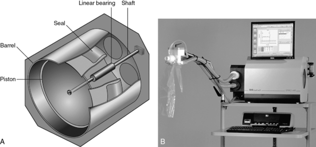
The piston of the standard dry rolling seal spirometer (Figure 11-2, B) travels horizontally, eliminating the need for counterbalancing. The vertically mounted version (see Figure 11-1, B) depends on a lightweight piston and the rolling seal to reduce resistance to breathing. Temperature corrections (from ATPS to BTPS) are made by applying a correction factor to the digital value stored in the computer. A one-way breathing circuit and CO2 scrubber may be added so that dry rolling seal spirometers can be used for rebreathing tests in much the same way as water-seal spirometers.
To perform studies such as the open-circuit nitrogen washout test, a “dumping” mechanism is attached to the spirometer. The dumping device empties the spirometer after each breath or after a predetermined volume has been reached. Addition of an automated valve and alveolar sampling device allows the dry rolling seal spirometer to be used for single-breath diffusion studies. Dry rolling seal spirometers are typically capable of meeting the minimum standards recommended by the ATS-ERS (see Chapter 12).
Bellows-Type Spirometers
A third type of volume-displacement spirometer is the bellows or wedge bellows spirometer. Both devices consist of a collapsible bellows that folds or unfolds in response to breathing excursions. The conventional bellows design is a flexible accordion-type container. One end is stationary and the other end is displaced in proportion to the volume inspired or expired. The wedge bellows operates similarly except that it expands and contracts like a fan (Figure 11-3, A and B) One side of the bellows remains stationary; the other side moves with a pivotal motion around an axis through the fixed side. Displacement of the bellows by a volume of gas is translated either to movement of a pen on chart paper or to a potentiometer. For mechanical recording, chart paper moves at a fixed speed under the pen while a spirogram is traced. For computerized testing, displacement of the bellows is transformed into a DC voltage by a linear or rotary potentiometer. The analog signal is routed to an A/D converter and then to a computer.
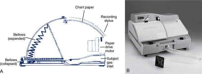
Both bellows-type spirometers (see Figure 11-3, A and B) can be used to measure vital capacity and its subdivisions, as well as FVC, FEV1, expiratory flows, and MVV. Some bellows-type spirometers, especially those that are mounted vertically, are designed to measure expiratory flows only. These types expand upward when gas is injected, then empty spontaneously under their own weight. Horizontally mounted bellows can usually be set in a mid-range to record both inspiratory and expiratory maneuvers. This allows F-V loops to be recorded. With appropriate gas analyzers and breathing circuitry, bellows systems may be used for gas dilution FRC determinations and Dlco measurements. Most bellows-type spirometers meet ATS recommendations for flow and volume accuracy.
Flow-sensing spirometers
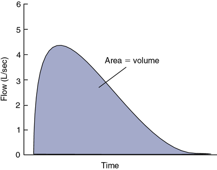
In contrast to the volume-displacement spirometer is the flow-sensing spirometer, or pneumotachometer. The term pneumotachometer describes a device that measures gas flow. Flow-sensing spirometers use various physical principles to produce a signal proportional to gas flow. This signal is then integrated to measure volume in addition to flow. Integration is a process in which flow (volume per unit of time) is divided into a large number of small intervals (time). The volume from each interval is summed (Figure 11-4). Integration can be performed easily by an electronic circuit or by computer software. Accurate volume measurement by flow integration requires an accurate flow signal, accurate timing, and sensitive detection of low flow.
One type of device that responds to bulk flow of gas is the turbine or impeller. Integration may be unnecessary because the turbine directly measures gas volumes. Some turbine spirometers produce volume pulses in which each “pulse” equals a fixed volume. These spirometers count pulses very accurately. Most flow-sensing spirometers use tubes through which laminar airflow is possible (see Evolve website (http://evolve.elsevier.com/Mottram/Ruppel/)). Five basic types of flow sensors are commonly used:
Turbines
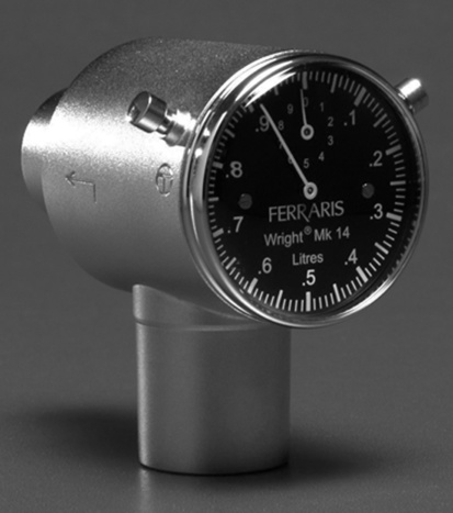
The simplest type of flow-sensing device is the turbine, or respirometer. This instrument consists of a vane connected to a series of precision gears. Gas flowing through the body of the instrument causes the vane to rotate, registering a volume (Figure 11-5). The respirometer can be used to measure slow vital capacity (VC). It can also be used for ventilation tests such as VT and  . One such device is the Wright respirometer. This respirometer can measure volumes accurately at flows between 3 and 300 L/min. At flows greater than 300 L/min (5 L/sec), the vane is subject to distortion. Because of this limitation, it should not be used to measure FVC when the patient is capable of flows greater than 300 L/min. At low flows (less than 3 L/min), inertia of the vane-gear system may underestimate volume.
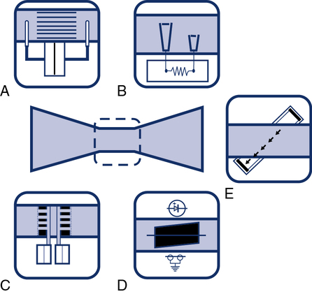
An adaptation of the turbine flow device includes a photo cell and light source that is interrupted by the movement of the vane or impeller (Figure 11-6, D). Rotation of the vane interrupts a light beam between its source and the photo cell. This produces a pulse, with each pulse equivalent to a fixed gas volume. The pulse count is summed to obtain the volume of gas flowing through the device. The signal produced may not be linear across a wide range of flows because of inertia or distortion of the rotating vane.
Pressure Differential Flow Sensors
Pressure differential flow sensors are among the most common implementations of flow sensing. They consist of a tube containing a resistive element. The resistive element allows gas to flow through it but causes a pressure drop (see Figure 11-6, A). The pressure difference across the resistive element is measured by means of a sensitive pressure transducer. The transducer usually has pressure taps on either side of the element (Figure 11-7, A). The pressure differential across the resistive element is proportional to gas flow as long as flow is laminar. This flow signal is integrated to measure volume (see Figure 11-4). Turbulent gas flow upstream or downstream of the resistive element may interfere with the development of true laminar flow. Most pneumotachometers attempt to reduce turbulent flow by tapering the tubes in which the resistive elements are mounted.
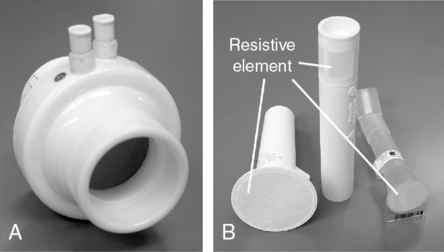
Some flow-sensing spirometers use resistive elements such as porous paper, rendering the flow sensor disposable (see Figure 11-7, B). These devices usually have a single pressure tap upstream of the resistive element. Pressure measured in front of the resistive element is referenced against ambient pressure. This design requires that the flow sensor be carefully “zeroed” before making any flow measurements. These types of flow sensors may be more susceptible to moisture or debris on the resistive element causing volumes and flows to increase with each successive blow. The flow sensor will need to be replaced if the technologist notices this occurring. The accuracy of spirometers using this type of flow sensor often depends on how carefully the disposable resistive elements are manufactured. If the resistance varies widely from sensor to sensor, each unit may need to be calibrated before use to ensure accuracy. Some manufacturers calibrate their disposable sensors and then provide a calibration code with each sensor. This code is used to identify a particular sensor by the software in the spirometer. One method of identifying the correct calibration factor for individual flow sensors is to imprint the sensor with a bar code (see Figure 11-7, B). The spirometer then includes a simple bar code reader to identify the appropriate calibration factors. Some portable spirometer systems that use precalibrated flow sensors do not provide for user calibration. However, verification of accuracy (using a 3-L syringe) is usually possible, even if the manufacturer has not provided for this in the software accompanying the spirometer.
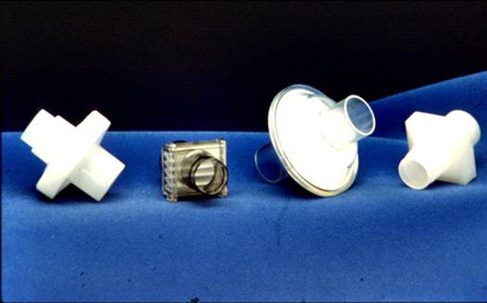
Infection control of pressure-differential flow sensors depends on their placement in the spirometer. In open-circuit systems in which only exhaled gas is measured, only the mouthpiece needs to be changed between patients. If inspiratory and expiratory flows are measured, the flow sensor itself may need to be disinfected between patients. Disassembly and cleaning of flow sensors usually require that the spirometer be recalibrated. Disposable or single-use sensors avoid this problem. In-line bacteria filters may be used to isolate the pneumotachometer from potential contamination. The spirometer should meet all ATS-ERS requirements for range, accuracy, and flow resistance with the filter in place (see Chapter 12). (See Figure 11-8.) If a filter is used, calibration with the filter in-line is usually required. The effect of bacteria filters on spirometric measurements has been reported to cause small errors in measured flows and volumes (30-50 mLs). Use of in-line filters can be an efficient and effective component of the PF laboratory’s infection control program.
Heated-Wire Flow Sensors
Heated-wire flow sensors are a third type of flow-sensing spirometer. They are based on the cooling effect of gas flow. A heated element, usually a thin platinum wire, is situated in a laminar flow tube (see Figure 11-6, B). Gas flow past the wire causes a temperature decrease so that more current must be supplied to maintain a preset temperature. The current needed to maintain the temperature is proportional to gas flow. The heated element usually has a small mass so that slight changes in gas flow can be detected. The flow signal is integrated electronically or by software to obtain volume measurements. The heated wire is usually protected behind a screen to prevent impaction of debris on the element. Debris or moisture droplets on the element can change its thermal characteristics. Some systems use two wires (Figure 11-9). One measures gas flow, and the second serves as a reference. Most heated-wire flow sensors maintain a temperature higher than 37°C. Heating prevents condensation from expired air that might interfere with sensitivity of the element.
Pitot Tube Flow Sensors
Pitot tube flow sensors are a fourth type of flow sensor. They use the Pitot tube principle. The pressure of gas flowing against a small tube is related to the gas’s density and velocity. Flow can be measured by placing a series of small tubes in a flow sensor and connecting them to a sensitive pressure transducer (see Figure 11-6, C). The pressure signal must be linearized and integrated as described for other flow-sensing devices. In practice, two sets of Pitot tubes are mounted in the same sensor so that bidirectional flow can be measured (Figure 11-10). A wide range of flows can be accommodated by using two or more pressure transducers with different sensitivities. Because this type of flow-sensing device is affected by gas density, software correction for different gas compositions is necessary. This is accomplished by sampling the gas, analyzing O2 and CO2, and applying the necessary correction factors. Software corrections for test gases used for various pulmonary function tests (e.g., Dlco) can be easily applied.
Ultrasonic Flow Sensors
Gas flow can be detected and measured by passing high-frequency sound waves across the stream of gas. Ultrasonic transducers on either side of the flow tube transmit sound waves alternately across the tube. By passing the sound waves at an angle to the flow of gas in two different directions, bidirectional flow can be measured (see Figure 11-6, E). The sound waves are sped up by gas flowing in one direction and slowed down by gas flowing in the opposite direction. By measuring the “transit time” of the pulses with a very accurate digital clock, flow can be integrated to measure volume. Analyzing the change in frequency of the sound waves passing through the flowing gas has the advantage of not being affected by the gas composition, temperatures, or humidity. In addition, there are no moving parts or elements to become occluded when measuring exhaled gas.
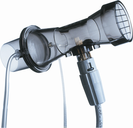
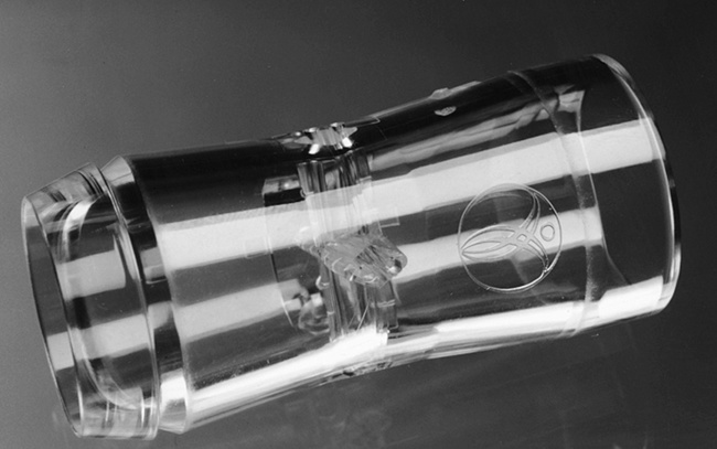
A distinct advantage of measuring gas flow by means of ultrasonic pulses is that a disposable flow tube can be inserted between the transducers, thus eliminating problems with cross-contamination between subjects. A further advantage of this design is that the disposable flow tube does not require calibration because it simply acts as a transparent barrier separating exhaled gas from the sensing transducers (Figure 11-11).
Flow Sensor Summary
Most types of the flow sensors produce a signal that is not linear across a wide range of flows. Some systems use two separate flow sensors (or variable orifices) to accommodate both low and high flows. Better accuracy can be obtained for flow and volume by matching the flow range of the sensor to the physiologic signal. Most flow-based spirometers “linearize” the flow signal electronically or by means of software corrections. In many systems, a simple “look-up table” is stored in the computer. The flow signal is continuously checked against the table and corrected. By combining a calibration factor (see Chapter 12) with the look-up table corrections, very accurate flow and integrated volume measurements are possible. Flows and volumes are corrected before variables such as FEV1 are measured.
Problems related to electronic “drift” require flow sensors to be “zeroed” frequently. Zeroing is simply a one-point calibration in which the output of the transducer is set to zero under a condition of no flow. Many systems “zero” the flow signal immediately before a measurement. Zeroing corrects for much of the electronic drift that occurs. A true zero requires no flow through the flow sensor. Thus, the flow sensor must be held still or occluded during the zero maneuvers. Most flow-based systems use a 3-L syringe for calibration. By calibrating with a known volume signal, the accuracy of the flow sensor and the integrator can be checked with one input. Calibration and quality-control techniques for volume-displacement and flow-sensing spirometers are included in Chapter 12.
Portable (Office) Spirometers
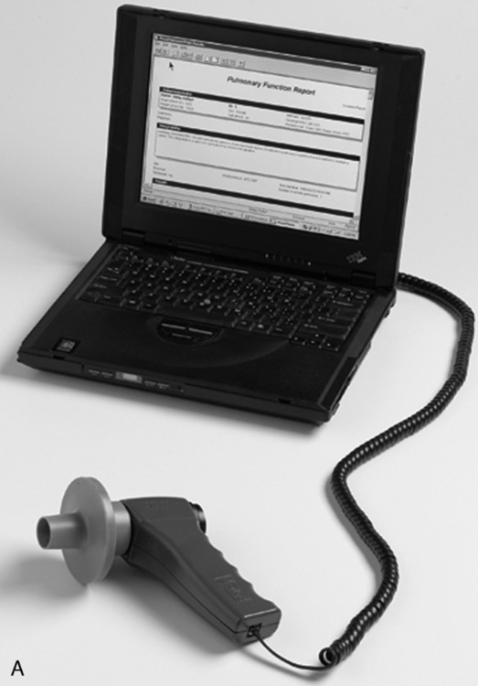
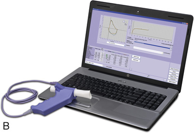
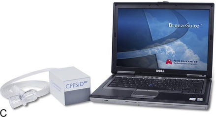
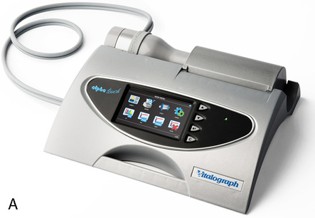
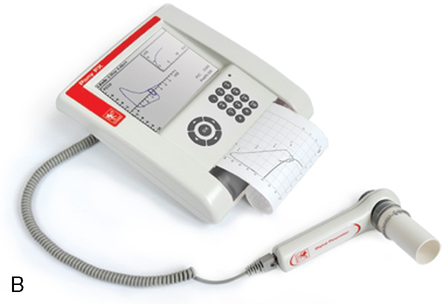
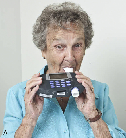
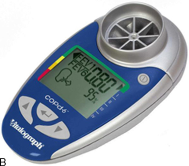
Many flow-sensing spirometers interface directly with personal computers (Figure 11-12, A-C), typically a laptop computer. Other spirometers use an interface card that plugs directly into a personal computer (PC). With the appropriate software installed on the PC, spirometry can be performed. Other spirometers place the necessary electronic components in the flow sensor head or in an external adapter. This implementation allows the flow sensor to be connected to a serial port or USB (universal serial bus) port, both of which are standard on most computers. The pressure transducer and electronics for flow-based spirometry can also be mounted on a removable card. These cards allow spirometry to be performed with handheld computers, laptop computers, or personal digital assistants (PDAs). Many flow-based spirometers use dedicated microprocessors (Figure 11-13). Some of these are very compact so that the entire device is not much larger than a calculator. These designs allow the units to be handheld and portable.
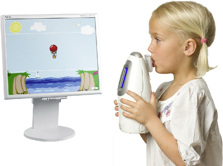
The National Lung Health Education Program (NLHEP) provides recommendations for office spirometers to be used in primary care settings (Box 11-1). The goal of these recommendations is to standardize spirometry to promote early detection of chronic obstructive pulmonary disease (see Figure 11-14). Office spirometers should be simple and designed to measure three important parameters: FEV1, FEV6, and the FEV1/FEV6 ratio. To provide accurate measurements, office spirometers should display automated messages describing the acceptability and repeatability of efforts. Automated interpretation of simple spirometry can be performed if test quality is acceptable and appropriate reference values are used. Display or printouts of spirograms are optional. Office spirometers should meet the accuracy recommendations of the ATS-ERS (see Chapter 12).
Peak flowmeters
Most peak flowmeters use similar designs. The patient expires forcefully through a resistor or flow tube that has a movable indicator attached (Figure 11-15). An orifice provides the resistance in most devices. The movable indicator is deflected in proportion to the velocity of air flowing through the device. PEF is then read directly from a calibrated scale. Because these devices are nonlinear, different flow ranges are usually available. High-range peak flowmeters typically measure flows as high as 850 L/min. Low-range meters measure up to 400 L/min (Table 11-1). Low-range peak flowmeters are useful for small children or for patients who have marked obstruction.
Table 11-1
Peak Flowmeter Recommended Ranges
| Children | Adults | |
| National Asthma Education Program | 100–400 L/min ± 10% | 100–700 L/min ± 10% |
| American Thoracic Society (1994) | 60–400 L/min ± 10% or 20 L/min, whichever is greater | 100–850 L/min ± 10% or 20 L/min, whichever is greater |
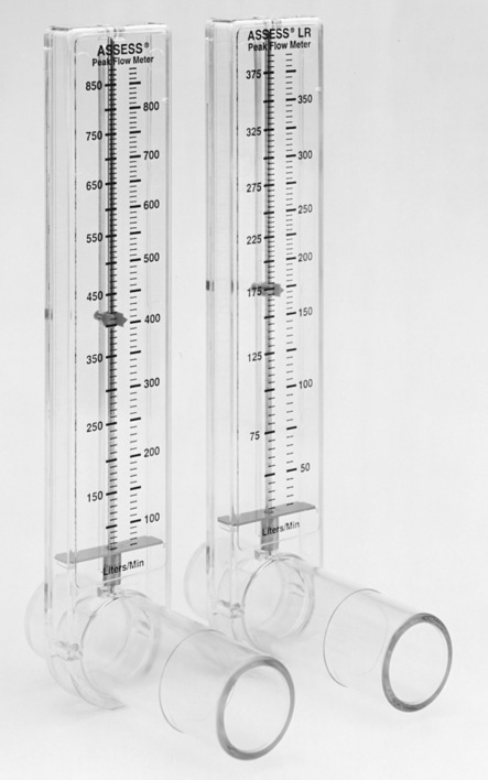
Although the simple design of portable peak flowmeters allows them to be used repeatedly, moisture or other debris can cause sticking of the movable parts. This can be problematic because it may suggest that the patient’s asthma has worsened. Some instruments can be cleaned but may need to be replaced periodically. Because portable peak flowmeters may have a limited life span, variability between same-model instruments should be 10% or 20 L/min as noted. This allows the patient to continue monitoring with a new device. Clear instructions on how to use and maintain the peak flowmeter should come with each device. Most peak flowmeters comply with the National Asthma Education Program’s “color zone” scheme for identifying clinically significant changes (see Chapter 2).
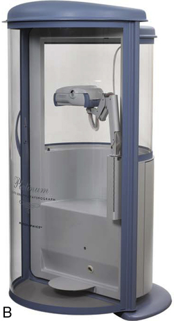
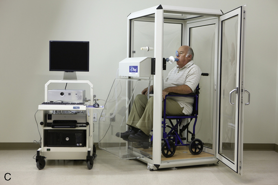
Body plethysmographs
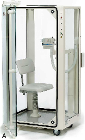
Body plethysmographs (Figure 11-16, A-C) are used in many pulmonary function laboratories. Body plethysmographs are also called body boxes. Two types of plethysmographs are available: the constant-volume, variable-pressure plethysmograph, and the flow or variable-volume plethysmograph. These are sometimes called the pressure plethysmograph and flow plethysmograph, respectively. Pressure-type plethysmographs are more commonly used than flow types. Both designs are used to measure thoracic gas volume (VTG) and airway resistance (Raw) and its derivatives (see Chapter 4). Both types of box use some type of pneumotachometer to measure flow, as well as a mouth pressure transducer with a shutter to measure alveolar pressure. They differ in the method used to measure volume change in the box, and therefore in the lungs.
 max Wheelchair box. (A: Courtesy nSpire Inc., Longmont, CO. B: Courtesy Medgraphics, Cardiopulmonary Diagnostics, St. Paul, MN. C: CareFusion Healthcare Critical Care Division, Palm Springs, CA.)
Pressure Plethysmographs
The pressure plethysmograph is based on an adaptation of Boyle’s law (see Evolve site http://evolve .elsevier.com/Mottram/Ruppel/). Volume changes in a sealed box are inversely related to pressure changes if temperature is constant. A sensitive pressure transducer monitors box pressure changes. Pressure change is related to volume change by calibration (see Chapter 12 for calibration techniques). Pressure changes result from compression and decompression of gas within both the patient’s chest and the box. If box temperature remains constant, each unit of pressure change equals a specific volume change. For example, a volume change of 15 mL may result in a pressure change of 1 cm H2O. After the box has been calibrated empty, the calibration factor changes slightly when a patient enters the plethysmograph. This change is easily corrected using an estimate of the volume displaced by the patient (based on the patient’s weight).
Flow Plethysmographs
In both types of plethysmograph, a flow sensor (i.e., pneumotachometer) is needed to measure airflow at the mouth (Figure 11-17). Flow measurement is required to compute Raw. The flow signal is also used to determine end-expiration for shutter closure in VTG measurements. The pneumotachometer must be linear across the range of flows encountered in spontaneous breathing and panting (±2 L/sec) and should meet all ATS-ERS requirements for spirometers (e.g., range, accuracy, frequency response) for measurement of VC and/or FVC. Heated Fleisch or Silverman types of pressure-differential pneumotachometers are often used in the plethysmograph. Pitot tube or heated-wire flow transducers can also be used.
Recording of plethysmographic maneuvers is usually performed by a computer. Breathing efforts are displayed in real time, allowing the technologist to elicit proper maneuvers from the patient. The real-time display assists in ensuring that panting maneuvers are performed correctly; some systems display prompts or flags so that the patient can be coached to pant at the correct frequency. The computer then stores the data and performs the necessary calculations to compute thoracic gas volume and airway resistance. Because the computer can track volume changes in the body box, VTG and airway resistance are sometimes measured from the same maneuver. The patient breathes normally to establish the end-expiratory level, the shutter is closed and then the patient pants. When the pre-set number of seconds has elapsed, the shutter opens (see Chapter 4). The volume change between the established end-expiratory level and the point at which the shutter was closed is then used to “correct” the measured VTG so that it equals the patient’s FRC. If VTG is measured at lung volumes other than FRC, the alveolar pressure should also be corrected for any difference from ambient pressure (i.e., PB).
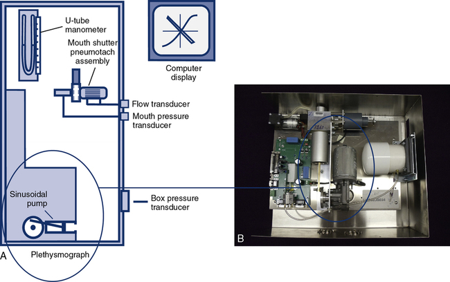
Most plethysmographs include the necessary signal-generating devices to perform physical calibration (see Chapter 12). A pressure manometer (or fluid-filled U-tube) may be mounted on the box for calibration of the mouth pressure transducer. Some systems provide a fixed pressure signal for mouth pressure calibration. A small syringe (30–50 mL) driven by an electric motor allows calibration of the box pressure transducer. The motorized syringe usually produces a sine-wave flow with frequency that can be varied. This allows checking of box pressure calibration at various frequencies. Most computerized plethysmographs use a standard 3-L syringe to calibrate the pneumotachometer or flow sensor. However, a flow generator and rotameter (i.e., a flowmeter) may be included for flow calibration. Computerized plethysmograph systems provide automated calibration of transducers. The output of the transducer (i.e., its amplified signal) is measured, and the computer generates a software correction factor. This correction is then applied to every measurement made with the transducer. Some manufacturers also supply quality control (QC) devices such as an isothermal lung analog (see Chapter 12). These devices provide QC to verify calibration of transducers and appropriateness of software correction factors.
The ease with which a patient can enter the plethysmograph and perform the required maneuvers is an important feature. Some patients may experience claustrophobia when inside the plethysmograph. Older boxes used a plywood cabinet to provide the necessary rigidity so that pressure changes were not attenuated. Boxes made of durable plastics are largely transparent and less confining for the patient (see Figure 11-16) while maintaining the necessary rigidity. Most plethysmographs contain 500–700 L of volume and can accommodate even large patients. Careful design allows the patient to easily enter the box. Some plethysmographs are large enough to accommodate patients in wheelchairs. Others use a clamshell design so that the patient may be seated and the box closed around him or her. Most plethysmographs provide an internal switch or mechanism that allows patients to open the box from inside if they become uncomfortable.
Breathing valves
Directional Valves
Another common valve design is that used to separate inspired from expired gas, often called a two-way nonrebreathing valve. This type of directional valve consists of a T-shaped body with three ports and two separate diaphragms (Figure 11-18). The diaphragms allow gas to flow in one direction only. The patient connection is between the diaphragms, effectively separating inspired from expired gas. Two-way nonrebreathing valves are used in exercise testing, metabolic studies, or any procedure requiring collection, measurement, or analysis of exhaled gas. The valve body may contain a tap for the connection of gas sample tubing. This tap is typically placed between the diaphragms so that both inspired and expired gas can be sampled.
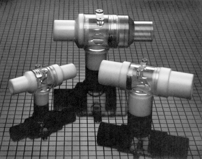
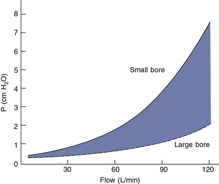
Low resistance to flow is also a critical characteristic of one-way and two-way valves. Resistance to flow through most valves is nonlinear and depends on the cross-sectional area of valve leaflets or diaphragms (Figure 11-19). Resistance is usually not critical for tests in which flows of less than 1 L/sec occur. Small-bore (15–22 mm) directional valves can be selected based on an appropriate dead space volume. Most small-bore nonrebreathing valves have a resistance in the range of 1–2 cm H2O/L/sec at flows of up to 1 L/sec (60 L/min). However, if the patient breathes through the valve for long intervals, even a small resistance may result in respiratory muscle fatigue and changes in the ventilatory pattern. Applications such as exercise testing typically involve increased flows. Large-bore, two-way valves are indicated when flows greater than 1 L/sec (60 L/min) can be expected to develop. Pressures less than 3 cm H2O can be maintained even at flows of 5 L/sec (300 L/min) with large-bore valves. Saliva and moisture may collect in valves during prolonged tests (e.g., exercise or eucapnic hyperventilation). Valves with “saliva traps” may be needed for these procedures. If a valve is used in a spirometry circuit, it must have very low resistance to meet the ATS-ERS recommendation of less than 1.5 cm H2O/L/sec at flows of 12 L/sec. Valves used in a Dlco circuit should produce a total resistance of less than 1.5 cm H2O/L/sec at flows of 6 L/sec.
Pulmonary gas analyzers
Oxygen Analyzers
Oxygen analysis can be performed by several different methods. Table 11-2 lists some types of O2 analyzers available. Two types are used for rapid analysis of O2 such as breath-by-breath exercise tests: the polarographic electrode and zirconium fuel cell. The other O2 analyzers listed are used for specialized applications, including patient monitoring.
Table 11-2
| Type | Applications | Advantages/Disadvantages |
| Paramagnetic | Monitoring | Discrete sampling only |
| Polarographic electrode | Monitoring, exercise testing, metabolic studies | Discrete or continuous sampling; requires special electronic circuitry for fast response (200 ms) |
| Galvanic cell (fuel cell) | Monitoring | Continuous sampling; similar to polarographic but does not require polarizing voltage |
| Zirconium cell | Breath-by-breath exercise and metabolic studies | Heated (650°C–800°C) electrochemical sensor; fast response useful for continuous sampling; thermal stabilization required |
| Gas chromatograph | Exercise testing, monitoring, metabolic measurements | Discrete sampling; response time approx. 30 sec; very accurate; multiple gas analysis |
Infrared Absorption (CO2, CO) Analyzers
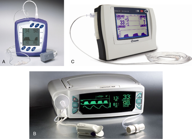
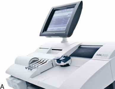
Several types of respiratory gas analyzers are based on absorption of infrared radiation to measure gas concentrations. Infrared absorption is used in CO analyzers for Dlco tests. Infrared CO2 analyzers are used for exercise testing, metabolic studies, and bedside monitoring (capnography) in critical care (Figure 11-20, A-C).
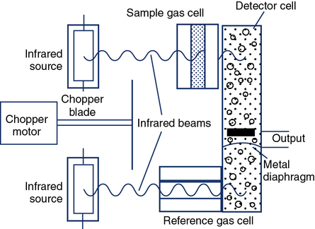
Certain gases (e.g., CO2 and CO) absorb infrared radiation. A common type of infrared analyzer uses two beams of infrared radiation directed through parallel cells. One cell contains sample gas, while the other contains a reference gas. The two beams converge on a single infrared detector (Figure 11-21). A small motor rotates an interrupter or “chopper” between the infrared source and the cells. The chopper blades alternately interrupt the infrared radiation passing through the sample and reference cells. If the sample and reference gases have the same concentration, the radiation reaching the detector is constant. However, when a sample with a different gas concentration is introduced, the radiation reaching the detector varies in a rhythmic fashion. This causes a vibration in the detector that is translated into a pulsatile signal proportional to the difference between the two beams.
Infrared analyzers used to measure CO (and, in some cases, tracer gas) during the Dlco test need to have a linear output because the calculation of Dlco commonly uses the ratio of CO to tracer gas (see Chapter 3). The analyzer should display nonlinearity of 0.5% or less of full scale across the range of gas concentrations typically used (approximately 0.3% for CO). Although the output of the infrared detector may be nonlinear, it can be easily corrected electronically or by means of a look-up table in software. For measuring CO and tracer gases during Dlco tests, the analyzer needs to be stable (i.e., no drift) for at least as long as the test may last (typically 30 seconds). Because water vapor and CO2 affect the measurement of CO, these gases need to be removed (“scrubbed”) before reaching the infrared detector.
Emission Spectroscopy Analyzers
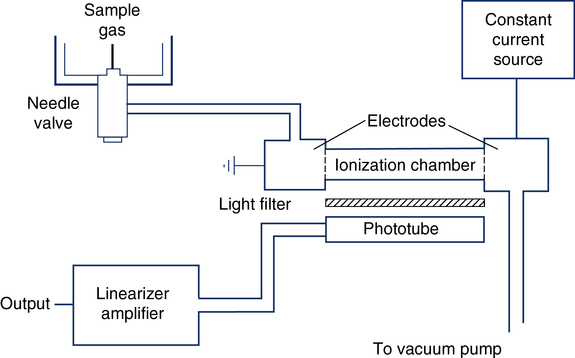
The single-breath and multiple-breath N2-washout tests (open-circuit FRC determination) use N2 analysis. The Geissler tube ionizer is an N2 analyzer based on the principle of emission spectroscopy (Figure 11-22). This instrument consists of an enclosed ionization chamber that contains two electrodes and a photo cell. A vacuum pump creates a constant low pressure in the ionization chamber by bleeding gas through a needle valve. The needle valve draws gas to be sampled from the breathing circuit. When current is supplied to the electrodes, the N2 between them is ionized and emits light. After being filtered, this light is monitored by a photo detector. The intensity of the light is directly proportional to the concentration of N2 in the sample. The current, distance between electrodes and gas pressure must remain constant. The photo detector converts the light signal into a DC voltage. This analog signal is then amplified, linearized, and directed to an appropriate meter or analog-to-digital converter. The Geissler tube ionizer allows continuous and rapid analysis of N2 with response times typically less than 100 msec.
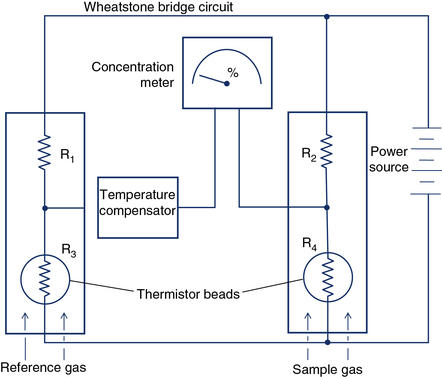
Thermal Conductivity Analyzers
Measurement of FRC by the closed-circuit method requires He analysis. Some Dlco systems also analyze helium as the tracer gas. Thermal conductivity analyzers measure gas concentrations in a sample by detecting the rate at which different gases conduct heat. Heated wires or beads (thermistors) are exposed to the gas sample. The concentration of a specific gas can be detected by measuring the change in electrical resistance of the thermistors. Two glass-coated thermistors serve as sensing elements connected by a Wheatstone bridge circuit (Figure 11-23). Thermistors change temperature and electrical resistance as a function of the molecular weight of the gases surrounding them. One thermistor serves as a reference. A difference in the concentration of gases between two thermistors can be detected because differences in heat conducted away alter the electrical resistance in the circuit. He analyzers use a reference cell containing no helium (He). Other gases can be analyzed by means of thermal conductivity if no interfering gases are present. Thermal conductivity analyzers are used in conjunction with gas chromatography (see the section on gas chromatography). Water vapor and CO2 must be removed before He analysis. Thermal conductivity analyzers can be used for continuous or discrete measurements but have response times in the range of 10–20 seconds. Thermal conductivity analyzers cannot be used to detect rapid changes in gas concentration.
Gas Chromatography
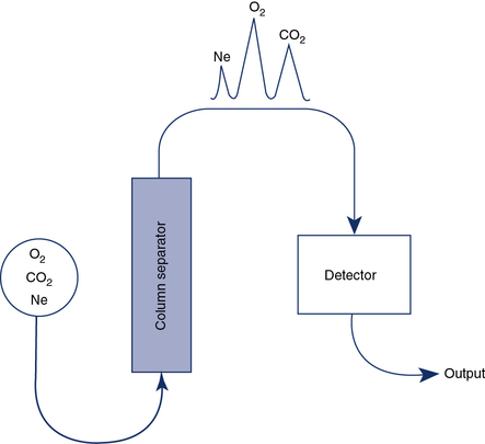
Gas chromatography combines a means of separating a sample into component gases and a detector for measuring concentrations of the components. The detector is usually a thermal conductivity analyzer as previously described. Most chromatographs use the principle of column separation to segregate the component gases of the sample (Figure 11-24). The chromatograph column contains a packing material that impedes movement of gas molecules, depending on their size. The material is usually a high-surface-area inorganic or polymer packing. Some columns also use materials that combine chemically with specific gases. A combination of columns allows a wide range of gases to be analyzed with a single detector. He is used as a carrier gas because of its high thermal conductivity. The sample gas, along with the He carrier gas, is injected into the column. Component gases exit the column at varying rates and are detected by a thermal conductivity analyzer. The concentrations of each gas can be determined by comparing the output of the thermal conductivity analyzer with a known calibration gas. When He is used as the carrier gas, it cannot be used as an inert indicator for lung volume determinations or diffusing capacity measurements. Neon, which is relatively insoluble, may be substituted for He in these tests. Water vapor and CO2 are usually removed from the sample to prevent contamination of the separator column.
Chemoluminescence Analyzers
Chemoluminescence analyzers are based on the principle that when two reactants are mixed to form an excited intermediate state, the intermediate may emit light as it decays back to a lower energy level. Chemoluminescence is routinely used to measure nitric oxide (see FeNO in Chapter 10) to assess airway inflammation. Ozone may be combined with NO to form NO2 (nitrogen dioxide) in an excited state:
< ?xml:namespace prefix = "mml" />

[◊] = represents decay to a lower energy state
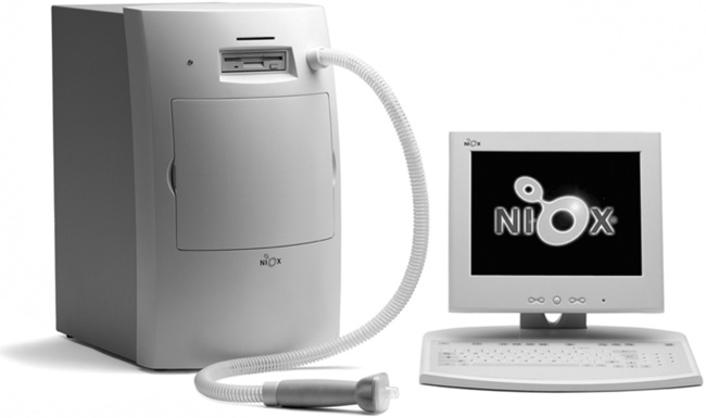
The activated NO2 luminesces (i.e., emits light) in visible and infrared wavelengths as it decays to a lower energy state. A photomultiplier or charge-coupled device (CCD) counts photons emitted at a specific wavelength, which are proportional to the amount of NO in the sample. Figure 11-25 shows an example of one commercially available chemoluminescence analyzer for measurement of NO.
Specific recommendations for chemoluminescence NO analyzers have been published by the ATS-ERS (Table 11-3). Calibration of NO analyzers is critical because of the small gas concentrations typically involved (parts per billion [ppb]). Chemoluminescence analyzers used to measure FeNO should be calibrated with gases that span the range of values encountered in clinical practice. These ranges differ depending on whether airway or nasal NO is being measured. In addition to appropriate calibration gases, a zero gas that is free of NO is also required. Ambient air can be drawn through an NO scrubber to provide the zero gas. Chemoluminescence analyzers are sensitive to changes in ambient conditions, especially temperature, and may require recalibration if conditions change. Sample inlet flow also affects the temperature of the reaction chamber and must be carefully controlled.
Table 11-3
Specifications for Nitric Oxide Analyzers
| FeNO | Portable FeNO* | Nasal NO | |
| Range | 1–500 ppb | 5–300 ppb | 10 ppb–50 ppm |
| Sensitivity | 1 ppb | 3 ppb | 10 ppb |
| Accuracy | Better than 1 ppb | ± 5 ppb or max 10% | Better than 10 ppb |
| Response time (90%) | <500 ms | 2 min | <500 ms |
| Drift | <1% full scale/24 hr | NK | <1% full scale/24 hr |
| Reproducibility | Better than 1 ppb | Better than 5 ppb | Better than 10 ppb |
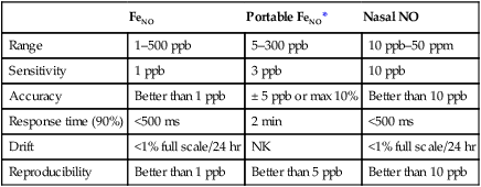
*NIOX MINO Product Specifications.
Modified from ATS-ERS recommendations for standardized procedures for the on-line and off-line measurement of exhaled lower respiratory nitric oxide and nasal nitric oxide. Am J Respir Crit Care Med. 2005; 171:912-930. (Courtesy Aerocrine Inc., New York, NY.)
An electrochemical sensor has been developed, based on the amperometric technique that can measure exhaled nitric oxide. The technique uses the production of a current when a voltage potential is applied between two electrodes (basic principle used in the PO2 electrode). The utilization of this analyzer allowed for the development of a hand-held (portable) exhaled nitric oxide device (Figure 11-26).
Blood gas analyzers, oximeters, and related devices

pH Electrodes
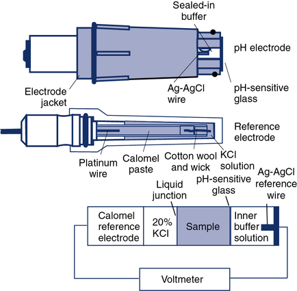
The traditional glass pH electrode contains a solution of constant pH on one side of a glass membrane. The sample to be analyzed is brought into contact with the other side of the pH-sensitive glass (Figure 11-27). The difference in pH on either side of the glass causes a potential difference, or voltage. To measure this potential, two half-cells are used: one for the constant solution and one for the sample. The constant solution half-cell (i.e., the measuring electrode) is usually a silver–silver chloride wire. The external half-cell is usually a saturated calomel (i.e., approximately 20% KCl) electrode called the reference electrode. The reference electrode makes contact with the unknown solution by means of a permeable membrane or a liquid junction. These half-cells are connected to a voltmeter calibrated in pH units. The voltage difference between the two electrodes is proportional to the pH difference of the solutions. Because the pH of one solution is constant, the developed potential is a measure of the pH of the sample. This type of analysis is thus referred to as a potentiometric because a potential is measured. Potentiometric electrodes are widely used in instruments with permanent electrodes as well as in some disposable cartridge–based systems.
Protein contamination of the pH-sensitive glass is a common problem that increases with the number of specimens analyzed. Routine cleaning with a proteolytic agent (e.g., bleach) reduces buildup of protein on the electrode tip. KCl depletion or blockage of the reference junction can also cause pH electrode malfunction. Contamination of reagents used for pH electrode calibration may also result in measurement errors. Daily (or more frequent) use of suitable quality control (QC) materials can detect these and other problems (see Chapter 12). pH measurements made with optical methods are dependent on how well the sample is mixed. Poorly mixed specimens may result in absorbances that do not accurately reflect the acid-base status of the patient. Fluorescent optodes are designed to separate the blood specimen from the sensor itself using an isolation layer to prevent contaminants from affecting the sensor.
Pco2 Electrodes
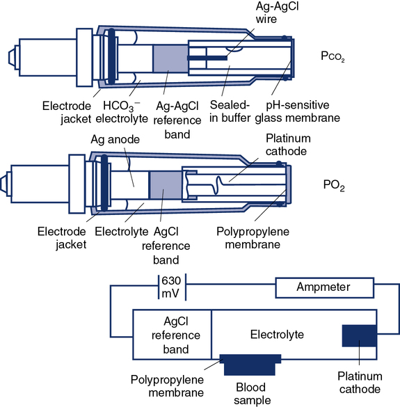
Traditional Pco2 electrodes (Severinghaus electrodes) measure Pco2 potentiometrically using an adaptation of the pH electrode (Figure 11-28). A combined pH-reference electrode is placed inside of a membrane-tipped plastic jacket. The jacket is filled with a bicarbonate electrolyte. The membrane is usually Teflon or a similar material permeable to CO2 molecules. A spacer or wick made of nylon is sometimes placed between the pH-sensitive glass and the membrane. The spacer ensures that a thin layer of bicarbonate electrolyte is in contact with the electrode. When the blood sample is introduced at the tip of the electrode, CO2 diffuses across the membrane. CO2 is hydrated in the electrolyte according to the following equation:

Analyzers that use the infrared photometric methodology typically use single-use measurement cuvettes, eliminating problems of contamination of the measuring chamber. However, photometric absorption measurements require that the specimen be well mixed. Fluorescent optode analyzers use an optical isolation layer to prevent contaminants and stray light from entering the optode. Guidelines for QC of blood gas electrodes are included in Chapter 12.
PO2 Electrodes
The standard PO2 electrode (Clark electrode) consists of a platinum cathode that is usually a thin wire encased in plastic or glass, together with a silver–silver chloride (Ag-AgCl) anode (see Figure 11-28.) Both anode and cathode are placed inside a plastic jacket that is tipped with a polypropylene or polyethylene membrane. This membrane is semipermeable and allows diffusion of oxygen molecules. The jacket is filled with phosphate–potassium chloride buffer. A polarizing voltage of approximately 630 mV is applied to the electrode. The cathode is slightly negative with respect to the anode. Because the electrode is polarized, it is referred to as a polarographic electrode. Oxygen is reduced (i.e., takes up electrons) at the cathode according to the following equation:

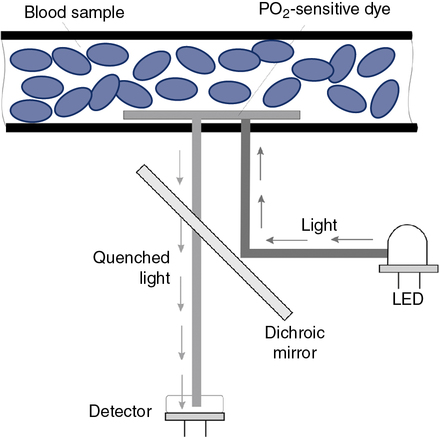
Optical methods of measuring PO2 include phosphorescence and fluorescence quenching. In each of these methods, a dye that emits light and is sensitive to the presence of O2 is used (Figure 11-29). The higher the PO2 is in the sensor or optode, the lower the phosphorescence or fluorescence (i.e., increased quenching of emitted light).
Laboratory Analyzers
Although the gas-measuring (PO2 and Pco2) electrodes and the pH electrode system can each be used separately, all three are usually implemented together in a blood gas analyzer (Figure 11-30). The three electrodes are mounted in a single measuring chamber. This allows a small blood sample (≤200 μl) to be analyzed. Most blood gas analyzers are microprocessor controlled. Sample aspiration, rinsing, and calibration can all be done automatically with program control. Standardization of these functions, especially calibration, reduces measurement error and improves precision. The microprocessor can calculate other blood gas values derived from pH, Pco2, and PO2, including  , total CO2, and base excess (BE). In addition to pH, Pco2, and PO2, most modern laboratory analyzers incorporate a hemoximeter to provide total Hb and its derivatives (e.g., O2Hb, COHb). Computerized analyzers can monitor automated calibrations and electrode performance to alert the technologist of existing or impending problems. The computer can monitor the level of reagents and calibrating solutions/gases as well. Some analyzers automatically perform quality control runs (i.e., auto QC) and monitor the results.


Point-of-Care Analyzers
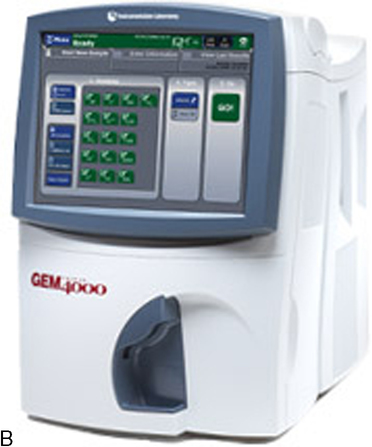
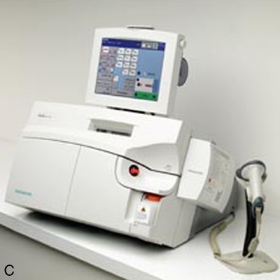
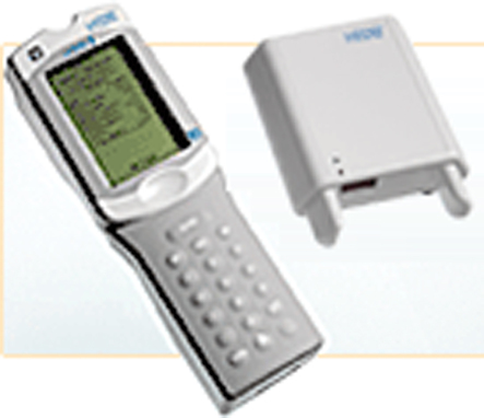
To provide rapid results of critical analytes (e.g., blood gases and electrolytes), portable or bedside analyzers (i.e., point-of-care [POC]) have become widely available (Figure 11-31). These devices are typically designed for use in the emergency department, critical care unit, or outpatient clinic. Most can be battery-operated, but some POC instruments require standard power. Blood gas measurement techniques differ slightly among models. Some POC blood gas analyzers use microelectrodes similar to those described previously, whereas others use spectrophotometry, infrared spectroscopy, or fluorescence quenching methods. Reagents, calibration materials, and waste containers are usually contained in disposable cartridges. Some POC systems use cartridges that allow a fixed number of analyses, whereas others use a single-patient sample chamber. Calibrations for POC systems that use multiple-specimen cartridges are usually performed in the traditional manner (see Chapter 12). These POC instruments use aqueous buffers in the single-patient chamber to perform calibration immediately before sample analysis. Single-use devices often have the sample chamber precalibrated by the manufacturer. Many POC instruments include ion-specific electrodes for analysis of electrolytes (e.g., K+, Na+, and Ca+) along with other metabolites and hematocrit. A few POC analyzers also incorporate hemoximetry in addition to pH, Pco2, and PO2.
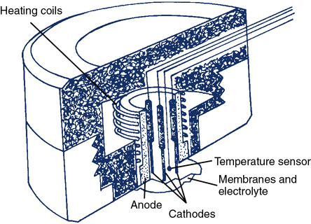
Transcutaneous PO2 and Pco2 Electrodes
The transcutaneous O2 electrode (tcPO2) operates on a principle similar to that of the polarographic electrode. The tcPO2 electrode typically consists of a ring-shaped silver anode heated by a coil to increase blood flow at the skin placement site. Inside the circular anode is a platinum cathode (Figure 11-32). All elements are enclosed in a plastic case. The face of the sensor is covered by a Teflon membrane. Electrolyte (KCl) is placed between the membrane and the sensor. A second layer of electrolyte and a cellophane membrane are added to form a double membrane. The current between the silver anode and platinum cathode is proportional to the PO2 diffusing through the skin and membrane. A feedback controller keeps the temperature constant at the skin site. This also compensates for changes in capillary blood flow and stabilizes the measurement.
Spectrophotometric Oximeters
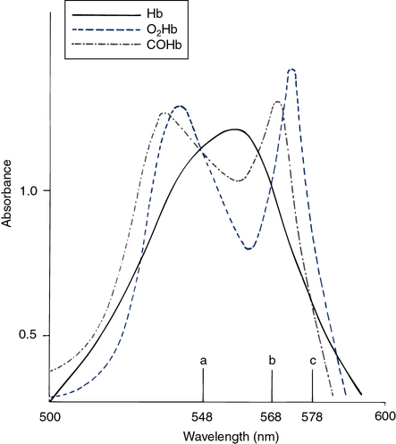
The hemoximeter analyzes the absorption of light in a blood sample at multiple wavelengths. At certain wavelengths, two or more forms of Hb have similar absorbances (Figure 11-33). These common wavelengths are termed isobestic points. An isobestic point for oxyhemoglobin (O2Hb), reduced Hb (RHb), and COHb is 548 nm. At this wavelength, the absorbance of a mixture of the three pigments is directly proportional to the total concentration of Hb. An isobestic point for O2Hb and RHb is 568 nm. The absorbance of COHb at this point is considerably higher. A change in absorbance at 568 nm compared with 548 nm indicates a change in the concentration of COHb relative to the sum of the concentrations of the other two species. The isobestic point for RHb and COHb is 578 nm, with O2Hb absorbance being considerably greater. The difference in absorbance at 578 nm indicates the concentration of O2Hb relative to the other two pigments. The total Hb concentration, O2Hb, COHb, and methemoglobin (MetHb) saturation can be determined by analyzing absorbances and solving simultaneous equations.
The hemoximeter provides the true O2Hb saturation (see the section on oxygen saturation in Chapter 6). This is particularly important if increased concentrations of COHb, MetHb, or other abnormal hemoglobins are present. Some automated blood gas analyzers calculate O2Hb saturation. Calculated saturation is based on the measured PO2 and pH at 37°C. This calculation assumes that the Hb has a normal P50 (see Chapter 6). Calculated O2Hb may significantly overestimate true saturation in the presence of increased levels of COHb or methemoglobin. The hemoximeter provides the most accurate estimate of the actual O2 saturation. Most laboratory blood gas analyzers and some POC analyzers combine blood gases and hemoximetry. These instruments provide pH, PCO2, PO2 and spectrophotometric measurements of Hb saturation, all performed with the same blood sample.
Hemoximeters may give erroneous Hb, O2Hb, or COHb readings if forms of hemoglobin are present that the instrument does not recognize. For example, blood from a newborn (e.g., containing fetal Hb) will give erroneous values if analyzed by an oximeter set up for adult blood. Substances that cause light scattering in the specimen (e.g., lipids resulting from lipid therapy) may also cause false readings. To function properly, the hemoximeter must hemolyze the sample so that Hb molecules are suspended in solution rather than contained within the red cells. Hemolysis is accomplished by chemical or mechanical disruption of red cell membranes. Incomplete hemolysis results in light scattering within the sample rather than simple absorption. Sickle cells are not easily disrupted, particularly by chemical lysis, and may result in false readings for O2Hb and COHb. Incomplete hemolysis may be difficult to detect unless whole-blood QC or proficiency testing is performed (see Chapter 12). Blood specimens used for hemoximetry must be well mixed or the concentration of Hb (i.e., total Hb) may be incorrect. Most hemoximeters report errors such as incomplete hemolysis or light scattering.
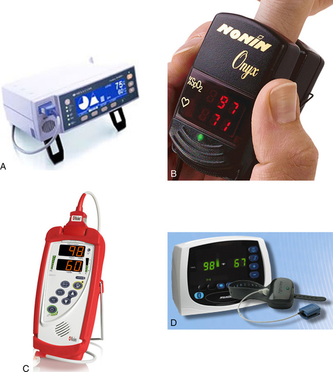
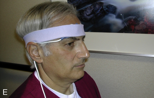
Pulse Oximeter
Pulse oximeters (Figure 11-34) are commonly used to assess oxygenation noninvasively. Pulse oximeters treat Hb as a filter that allows only red and near-infrared light to pass. The Lambert-Beer law relates total absorption in a system of absorbers to the sum of their individual absorptions.

The transmitted light at each wavelength consists of two components, the AC and DC components (Figure 11-35). The AC component varies with the pulsation of blood. The DC component represents light absorbed by tissue and venous blood. The DC component is larger than the AC and is relatively constant. The amplitude of both AC and DC levels depends on the intensity of the incident light. The AC component represents the arterial blood because the arterioles pulsate in the light path. By dividing the AC level by the DC level at each of the two wavelengths, the AC component is effectively corrected. The AC component then becomes a function of the extinction of O2Hb and RHb. The ratio just described then becomes:

2 = near-infrared wavelength (940 nm)
Most pulse oximeters use the AC signal from one channel (660 nm or 940 nm) to calculate pulse rate. An algorithm implemented by the microprocessor locates peaks in the waveform of the AC signal and counts them (see Figure 11-35). Some oximeters use this signal to display graphic representations of pulse waveforms. Pulse oximeters that measure absorption at multiple wavelengths (see Figure 11-34) can detect Hgb (SpHb), COHb (SpCO), and MetHb (SpMet), in addition to the standard SpO2.
Reflective Spectrophotometers

A specially designed pulmonary artery (Swan-Ganz) catheter contains fiberoptic bundles (Figure 11-36). This catheter has regular pressure-sensing ports, a balloon tip for flotation through the right side of the heart, and capability for cardiac output determinations. Three LEDs similar to those used in pulse oximeters illuminate blood flowing past the tip of the catheter via one of the optical fibers. A photodetector senses the reflected light and converts its intensity into a signal. A microprocessor calculates two independent ratios of reflected light intensities from the three wavelengths. Combining two reflected light intensity ratios reduces the instrument’s sensitivity to pulsatile blood flow or changing hematocrit. This design also minimizes changes caused by light scattering from red cell surfaces and the walls of the blood vessel. S o2 is calculated from the light ratios using programmed calibration curves, similar to those used for a pulse oximeter. As in a pulse oximeter, saturation measured is the saturation of functional Hb (see Chapter 6). S
 o2 determination by this method tends to be higher than that measured by a hemoximeter, especially if large amounts of COHb or MetHb are present. S
 o2 is then displayed and may be printed using a trend recorder (Figure 11-37).
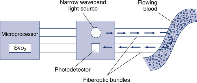
 o2. LEDs provide a narrow-waveband light source. Light is transmitted along one fiberoptic filament to blood flowing past the tip of the catheter. Light reflected from the blood is transmitted back to a photodiode by the second fiberoptic bundle. The light intensity signals are then evaluated by a microprocessor to calculate light intensity ratios. These ratios (usually two ratios are determined from three wavelengths) determine the S
 o2. The principle of reflective absorption can also be used for pulse oximetry.
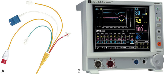


Computers for pulmonary function testing
All modern pulmonary function equipment uses computers in one form or another. Many spirometers use either a dedicated microprocessor (see Figure 11-13) or are interfaced to a desktop or laptop (Figure 11-12 and 11-38). Computerized pulmonary function systems allow sophisticated data handling and storage, accurate calculations, graphic display of maneuvers, and enhanced reporting capabilities. Some laboratories use networked computers in which each pulmonary function system has a dedicated workstation. Networked systems allow rapid exchange of information and centralized data storage and retrieval.
Data Acquisition and Instrument Control
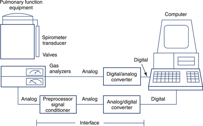
Computerized pulmonary function systems process analog signals from spirometers, plethysmographs, and gas analyzers. Equally important is the computer’s capacity to control instrument functions, such as switching valves or recording signals. Computer control allows the technologist to manage complex test maneuvers. Data acquisition and instrument control are implemented with an interface (Figure 11-39) between the computer and pulmonary function equipment. Similar principles are applied in large laboratory systems and in small handheld spirometers.
Pulmonary Function Data Storage and Programs
Database Storage
• Serial comparisons of multiple tests on a single patient may be extracted to plot a trend.
• Data from longitudinal studies on groups of patients may be extracted for statistical analysis or exported to an external program.
• Queries may be performed to extract data that match selected criteria.
• An unlimited number of report formats may be generated.
• Reference equations may be stored in a database format. This structure allows input of user-defined equations for predicting normal values.
Summary
• Spirometers that use either volume-displacement or flow-sensing principles are used for many different pulmonary function tests.
• Small computerized spirometers (office spirometers) are often used for testing in many areas outside of the traditional pulmonary function laboratory.
• Small, portable peak flow devices have been developed and are widely used in clinical and home settings.
• Body plethysmography, using either a pressure box or flow box, is commonly used for measuring lung volumes and airway resistance. Its design and ease of use have benefited from advances in electronics and computerization.
• Various types of pulmonary gas analyzers and their principles of operation are discussed along with how they are used for pulmonary function testing.
• Breathing valves and gas conditioning devices are described, with particular attention to selection and maintenance.
• Blood gas electrodes, along with other technologies used for blood gas analysis, are reviewed. Spectrophotometric oximeters, pulse oximeters, and related monitors are illustrated.
• Information on the components of computer systems, data acquisition and storage, and specific interfaces to pulmonary function equipment are presented.
[/level-membership-for-pulmolory-and-respiratory-category][not-level-membership-for-pulmolory-and-respiratory-category]Chapter 11
Pulmonary Function Testing Equipment
1. Describe two types of volume-displacement spirometers.
2. List at least two principles used by flow-sensing spirometers to measure volume.
3. Select a directional breathing valve for a specific testing situation.
4. Identify the types of gas analyzers used for diffusing capacity and dilutional lung volume tests.
5. Describe the function of commonly used gas conditioning devices.
1. Select and set up the basic components of a body plethysmograph.
2. Contrast and compare measurement of oxygen saturation by multiwavelength and pulse oximeters.
3. Identify the measurement principles of pH, Pco2, and Po2 blood gas devices.
4. Describe the important characteristics of an “office” spirometer.
5. Discuss various types of data storage applicable to pulmonary function data.
VOLUME-DISPLACEMENT spirometers
Water-Seal Spirometers
For more than 100 years, the water-seal spirometer was the basic tool used to measure lung volumes and flows. The spirometer consists of a large bell (7–10 L) suspended in a container of water with the open end of the bell below the surface of the water (Figure 11-1, A and B). A breathing circuit inserted into the interior of the bell allows for accurate measurement of gas volumes. The patient breathes into the spirometer, moving the bell up during expiration and down with inspiration. Each spirometer bell has a “bell factor” relating the vertical distance moved to a specific volume (milliliters or liters). For many years, movement of the bell was recorded using a pen to make a tracing on a rotating drum, called a kymograph. Volumes were measured from the kymograph tracing by using paper that incorporated the bell factor for the spirometer. Volumes measured in this way reflect the gas in the spirometer that is at keytermambient temperature, pressure, and saturation (ATPS). These volumes, such as vital capacity (VC), had to be corrected to body temperature, pressure and saturation (BPTS).
For simple spirometry, a single large-bore tube can be used for both inspiration and expiration. For rebreathing studies, the breathing circuit incorporates a carbon dioxide (CO2) absorber/scrubber (usually soda lime). Inspiratory and expiratory circuits are separated with one-way valves to reduce dead space. Water-seal spirometers are typically used for spirometry. They may also be used to measure ventilation, including , VT, and respiratory rate. Water-seal spirometers can be used to obtain flow-volume (F-V) curves, although their frequency response may be limited by their physical characteristics. By including the rebreathing apparatus described (see Figure 11-1), lung volumes by helium dilution can be obtained. In combination with an appropriate reservoir for the test gas, water-sealed spirometers can be used to perform diffusing capacity tests, both single-breath and rebreathing. The water-seal spirometer can be used as a reservoir for special gas mixtures such as those used for Dlco tests.
The Stead-Wells water-seal or dry-seal spirometer is still used, although not commonly. The Stead-Wells spirometer uses a lightweight plastic bell (Figure 11-1, B). The water-sealed bell “floats” in the water well, rising and falling with breathing excursions. In the dry-seal version, a rubberized seal connects the bell to the internal wall of the spirometer well. The rubber seal then “rolls” over itself, much the same as the dry rolling seal spirometer (see next section). The Stead-Wells bell is usually attached to a linear potentiometer that provides analog signals proportional to volume and flow. These signals are passed to a computer through an A/D converter. The Stead-Wells design is capable of meeting the minimum requirements for flow and volume accuracy recommended by the American Thoracic Society and European Respiratory Society (ATS-ERS) (see Chapter 12).
Dry Rolling Seal Spirometers
Another type of volume-displacement spirometer is the dry rolling seal spirometer. A typical unit consists of a lightweight piston mounted horizontally in a cylinder. A rod that rests on frictionless bearings supports the piston (Figure 11-2, A and B). The piston is coupled to the cylinder wall by a flexible plastic seal. The seal rolls on itself rather than sliding as the piston moves. A similar type of rolling seal may also be used with a vertically mounted, lightweight piston that rises and falls with breathing (as in the dry-seal Stead-Wells described in the preceding section). The maximum volume of the cylinder with the piston fully displaced is usually 10–12 L. The piston has a large diameter so that excursions of just a few inches are all that is necessary to record large volume changes. The piston is normally constructed of lightweight aluminum to reduce inertia. Mechanical resistance is kept to a minimum by the bearings supporting the piston rod and by the rolling seal itself.
The piston of the standard dry rolling seal spirometer (Figure 11-2, B) travels horizontally, eliminating the need for counterbalancing. The vertically mounted version (see Figure 11-1, B) depends on a lightweight piston and the rolling seal to reduce resistance to breathing. Temperature corrections (from ATPS to BTPS) are made by applying a correction factor to the digital value stored in the computer. A one-way breathing circuit and CO2 scrubber may be added so that dry rolling seal spirometers can be used for rebreathing tests in much the same way as water-seal spirometers.
To perform studies such as the open-circuit nitrogen washout test, a “dumping” mechanism is attached to the spirometer. The dumping device empties the spirometer after each breath or after a predetermined volume has been reached. Addition of an automated valve and alveolar sampling device allows the dry rolling seal spirometer to be used for single-breath diffusion studies. Dry rolling seal spirometers are typically capable of meeting the minimum standards recommended by the ATS-ERS (see Chapter 12).
Bellows-Type Spirometers
A third type of volume-displacement spirometer is the bellows or wedge bellows spirometer. Both devices consist of a collapsible bellows that folds or unfolds in response to breathing excursions. The conventional bellows design is a flexible accordion-type container. One end is stationary and the other end is displaced in proportion to the volume inspired or expired. The wedge bellows operates similarly except that it expands and contracts like a fan (Figure 11-3, A and B) One side of the bellows remains stationary; the other side moves with a pivotal motion around an axis through the fixed side. Displacement of the bellows by a volume of gas is translated either to movement of a pen on chart paper or to a potentiometer. For mechanical recording, chart paper moves at a fixed speed under the pen while a spirogram is traced. For computerized testing, displacement of the bellows is transformed into a DC voltage by a linear or rotary potentiometer. The analog signal is routed to an A/D converter and then to a computer.
Both bellows-type spirometers (see Figure 11-3, A and B) can be used to measure vital capacity and its subdivisions, as well as FVC, FEV1, expiratory flows, and MVV. Some bellows-type spirometers, especially those that are mounted vertically, are designed to measure expiratory flows only. These types expand upward when gas is injected, then empty spontaneously under their own weight. Horizontally mounted bellows can usually be set in a mid-range to record both inspiratory and expiratory maneuvers. This allows F-V loops to be recorded. With appropriate gas analyzers and breathing circuitry, bellows systems may be used for gas dilution FRC determinations and Dlco measurements. Most bellows-type spirometers meet ATS recommendations for flow and volume accuracy.
Flow-sensing spirometers
In contrast to the volume-displacement spirometer is the flow-sensing spirometer, or pneumotachometer. The term pneumotachometer describes a device that measures gas flow. Flow-sensing spirometers use various physical principles to produce a signal proportional to gas flow. This signal is then integrated to measure volume in addition to flow. Integration is a process in which flow (volume per unit of time) is divided into a large number of small intervals (time). The volume from each interval is summed (Figure 11-4). Integration can be performed easily by an electronic circuit or by computer software. Accurate volume measurement by flow integration requires an accurate flow signal, accurate timing, and sensitive detection of low flow.
One type of device that responds to bulk flow of gas is the turbine or impeller. Integration may be unnecessary because the turbine directly measures gas volumes. Some turbine spirometers produce volume pulses in which each “pulse” equals a fixed volume. These spirometers count pulses very accurately. Most flow-sensing spirometers use tubes through which laminar airflow is possible (see Evolve website (http://evolve.elsevier.com/Mottram/Ruppel/)). Five basic types of flow sensors are commonly used:
Turbines
The simplest type of flow-sensing device is the turbine, or respirometer. This instrument consists of a vane connected to a series of precision gears. Gas flowing through the body of the instrument causes the vane to rotate, registering a volume (Figure 11-5). The respirometer can be used to measure slow vital capacity (VC). It can also be used for ventilation tests such as VT and . One such device is the Wright respirometer. This respirometer can measure volumes accurately at flows between 3 and 300 L/min. At flows greater than 300 L/min (5 L/sec), the vane is subject to distortion. Because of this limitation, it should not be used to measure FVC when the patient is capable of flows greater than 300 L/min. At low flows (less than 3 L/min), inertia of the vane-gear system may underestimate volume.
An adaptation of the turbine flow device includes a photo cell and light source that is interrupted by the movement of the vane or impeller (Figure 11-6, D). Rotation of the vane interrupts a light beam between its source and the photo cell. This produces a pulse, with each pulse equivalent to a fixed gas volume. The pulse count is summed to obtain the volume of gas flowing through the device. The signal produced may not be linear across a wide range of flows because of inertia or distortion of the rotating vane.
Pressure Differential Flow Sensors
Pressure differential flow sensors are among the most common implementations of flow sensing. They consist of a tube containing a resistive element. The resistive element allows gas to flow through it but causes a pressure drop (see Figure 11-6, A). The pressure difference across the resistive element is measured by means of a sensitive pressure transducer. The transducer usually has pressure taps on either side of the element (Figure 11-7, A). The pressure differential across the resistive element is proportional to gas flow as long as flow is laminar. This flow signal is integrated to measure volume (see Figure 11-4). Turbulent gas flow upstream or downstream of the resistive element may interfere with the development of true laminar flow. Most pneumotachometers attempt to reduce turbulent flow by tapering the tubes in which the resistive elements are mounted.
Some flow-sensing spirometers use resistive elements such as porous paper, rendering the flow sensor disposable (see Figure 11-7, B). These devices usually have a single pressure tap upstream of the resistive element. Pressure measured in front of the resistive element is referenced against ambient pressure. This design requires that the flow sensor be carefully “zeroed” before making any flow measurements. These types of flow sensors may be more susceptible to moisture or debris on the resistive element causing volumes and flows to increase with each successive blow. The flow sensor will need to be replaced if the technologist notices this occurring. The accuracy of spirometers using this type of flow sensor often depends on how carefully the disposable resistive elements are manufactured. If the resistance varies widely from sensor to sensor, each unit may need to be calibrated before use to ensure accuracy. Some manufacturers calibrate their disposable sensors and then provide a calibration code with each sensor. This code is used to identify a particular sensor by the software in the spirometer. One method of identifying the correct calibration factor for individual flow sensors is to imprint the sensor with a bar code (see Figure 11-7, B). The spirometer then includes a simple bar code reader to identify the appropriate calibration factors. Some portable spirometer systems that use precalibrated flow sensors do not provide for user calibration. However, verification of accuracy (using a 3-L syringe) is usually possible, even if the manufacturer has not provided for this in the software accompanying the spirometer.
Infection control of pressure-differential flow sensors depends on their placement in the spirometer. In open-circuit systems in which only exhaled gas is measured, only the mouthpiece needs to be changed between patients. If inspiratory and expiratory flows are measured, the flow sensor itself may need to be disinfected between patients. Disassembly and cleaning of flow sensors usually require that the spirometer be recalibrated. Disposable or single-use sensors avoid this problem. In-line bacteria filters may be used to isolate the pneumotachometer from potential contamination. The spirometer should meet all ATS-ERS requirements for range, accuracy, and flow resistance with the filter in place (see Chapter 12). (See Figure 11-8.) If a filter is used, calibration with the filter in-line is usually required. The effect of bacteria filters on spirometric measurements has been reported to cause small errors in measured flows and volumes (30-50 mLs). Use of in-line filters can be an efficient and effective component of the PF laboratory’s infection control program.
Heated-Wire Flow Sensors
Heated-wire flow sensors are a third type of flow-sensing spirometer. They are based on the cooling effect of gas flow. A heated element, usually a thin platinum wire, is situated in a laminar flow tube (see Figure 11-6, B). Gas flow past the wire causes a temperature decrease so that more current must be supplied to maintain a preset temperature. The current needed to maintain the temperature is proportional to gas flow. The heated element usually has a small mass so that slight changes in gas flow can be detected. The flow signal is integrated electronically or by software to obtain volume measurements. The heated wire is usually protected behind a screen to prevent impaction of debris on the element. Debris or moisture droplets on the element can change its thermal characteristics. Some systems use two wires (Figure 11-9). One measures gas flow, and the second serves as a reference. Most heated-wire flow sensors maintain a temperature higher than 37°C. Heating prevents condensation from expired air that might interfere with sensitivity of the element.
Pitot Tube Flow Sensors
Pitot tube flow sensors are a fourth type of flow sensor. They use the Pitot tube principle. The pressure of gas flowing against a small tube is related to the gas’s density and velocity. Flow can be measured by placing a series of small tubes in a flow sensor and connecting them to a sensitive pressure transducer (see Figure 11-6, C). The pressure signal must be linearized and integrated as described for other flow-sensing devices. In practice, two sets of Pitot tubes are mounted in the same sensor so that bidirectional flow can be measured (Figure 11-10). A wide range of flows can be accommodated by using two or more pressure transducers with different sensitivities. Because this type of flow-sensing device is affected by gas density, software correction for different gas compositions is necessary. This is accomplished by sampling the gas, analyzing O2 and CO2, and applying the necessary correction factors. Software corrections for test gases used for various pulmonary function tests (e.g., Dlco) can be easily applied.
Ultrasonic Flow Sensors
Gas flow can be detected and measured by passing high-frequency sound waves across the stream of gas. Ultrasonic transducers on either side of the flow tube transmit sound waves alternately across the tube. By passing the sound waves at an angle to the flow of gas in two different directions, bidirectional flow can be measured (see Figure 11-6, E). The sound waves are sped up by gas flowing in one direction and slowed down by gas flowing in the opposite direction. By measuring the “transit time” of the pulses with a very accurate digital clock, flow can be integrated to measure volume. Analyzing the change in frequency of the sound waves passing through the flowing gas has the advantage of not being affected by the gas composition, temperatures, or humidity. In addition, there are no moving parts or elements to become occluded when measuring exhaled gas.
A distinct advantage of measuring gas flow by means of ultrasonic pulses is that a disposable flow tube can be inserted between the transducers, thus eliminating problems with cross-contamination between subjects. A further advantage of this design is that the disposable flow tube does not require calibration because it simply acts as a transparent barrier separating exhaled gas from the sensing transducers (Figure 11-11).
Flow Sensor Summary
Most types of the flow sensors produce a signal that is not linear across a wide range of flows. Some systems use two separate flow sensors (or variable orifices) to accommodate both low and high flows. Better accuracy can be obtained for flow and volume by matching the flow range of the sensor to the physiologic signal. Most flow-based spirometers “linearize” the flow signal electronically or by means of software corrections. In many systems, a simple “look-up table” is stored in the computer. The flow signal is continuously checked against the table and corrected. By combining a calibration factor (see Chapter 12) with the look-up table corrections, very accurate flow and integrated volume measurements are possible. Flows and volumes are corrected before variables such as FEV1 are measured.
Problems related to electronic “drift” require flow sensors to be “zeroed” frequently. Zeroing is simply a one-point calibration in which the output of the transducer is set to zero under a condition of no flow. Many systems “zero” the flow signal immediately before a measurement. Zeroing corrects for much of the electronic drift that occurs. A true zero requires no flow through the flow sensor. Thus, the flow sensor must be held still or occluded during the zero maneuvers. Most flow-based systems use a 3-L syringe for calibration. By calibrating with a known volume signal, the accuracy of the flow sensor and the integrator can be checked with one input. Calibration and quality-control techniques for volume-displacement and flow-sensing spirometers are included in Chapter 12.
Portable (Office) Spirometers
Many flow-sensing spirometers interface directly with personal computers (Figure 11-12, A-C), typically a laptop computer. Other spirometers use an interface card that plugs directly into a personal computer (PC). With the appropriate software installed on the PC, spirometry can be performed. Other spirometers place the necessary electronic components in the flow sensor head or in an external adapter. This implementation allows the flow sensor to be connected to a serial port or USB (universal serial bus) port, both of which are standard on most computers. The pressure transducer and electronics for flow-based spirometry can also be mounted on a removable card. These cards allow spirometry to be performed with handheld computers, laptop computers, or personal digital assistants (PDAs). Many flow-based spirometers use dedicated microprocessors (Figure 11-13). Some of these are very compact so that the entire device is not much larger than a calculator. These designs allow the units to be handheld and portable.
The National Lung Health Education Program (NLHEP) provides recommendations for office spirometers to be used in primary care settings (Box 11-1). The goal of these recommendations is to standardize spirometry to promote early detection of chronic obstructive pulmonary disease (see Figure 11-14). Office spirometers should be simple and designed to measure three important parameters: FEV1, FEV6, and the FEV1/FEV6 ratio. To provide accurate measurements, office spirometers should display automated messages describing the acceptability and repeatability of efforts. Automated interpretation of simple spirometry can be performed if test quality is acceptable and appropriate reference values are used. Display or printouts of spirograms are optional. Office spirometers should meet the accuracy recommendations of the ATS-ERS (see Chapter 12).
Peak flowmeters
Most peak flowmeters use similar designs. The patient expires forcefully through a resistor or flow tube that has a movable indicator attached (Figure 11-15). An orifice provides the resistance in most devices. The movable indicator is deflected in proportion to the velocity of air flowing through the device. PEF is then read directly from a calibrated scale. Because these devices are nonlinear, different flow ranges are usually available. High-range peak flowmeters typically measure flows as high as 850 L/min. Low-range meters measure up to 400 L/min (Table 11-1). Low-range peak flowmeters are useful for small children or for patients who have marked obstruction.
Table 11-1
Peak Flowmeter Recommended Ranges
| Children | Adults | |
| National Asthma Education Program | 100–400 L/min ± 10% | 100–700 L/min ± 10% |
| American Thoracic Society (1994) | 60–400 L/min ± 10% or 20 L/min, whichever is greater | 100–850 L/min ± 10% or 20 L/min, whichever is greater |
Although the simple design of portable peak flowmeters allows them to be used repeatedly, moisture or other debris can cause sticking of the movable parts. This can be problematic because it may suggest that the patient’s asthma has worsened. Some instruments can be cleaned but may need to be replaced periodically. Because portable peak flowmeters may have a limited life span, variability between same-model instruments should be 10% or 20 L/min as noted. This allows the patient to continue monitoring with a new device. Clear instructions on how to use and maintain the peak flowmeter should come with each device. Most peak flowmeters comply with the National Asthma Education Program’s “color zone” scheme for identifying clinically significant changes (see Chapter 2).
Body plethysmographs
Body plethysmographs (Figure 11-16, A-C) are used in many pulmonary function laboratories. Body plethysmographs are also called body boxes. Two types of plethysmographs are available: the constant-volume, variable-pressure plethysmograph, and the flow or variable-volume plethysmograph. These are sometimes called the pressure plethysmograph and flow plethysmograph, respectively. Pressure-type plethysmographs are more commonly used than flow types. Both designs are used to measure thoracic gas volume (VTG) and airway resistance (Raw) and its derivatives (see Chapter 4). Both types of box use some type of pneumotachometer to measure flow, as well as a mouth pressure transducer with a shutter to measure alveolar pressure. They differ in the method used to measure volume change in the box, and therefore in the lungs.
[/not-level-membership-for-pulmolory-and-respiratory-category]
