6 Power Systems for Implantable Pacemakers, Cardioverters, and Defibrillators
 Batteries


Major Components Of Batteries
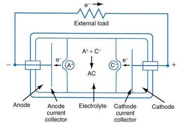
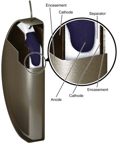
Figure 6-1 shows a simple battery; the major parts are the anode, cathode, and electrolyte. The anode and cathode must be physically separated, and both must be in contact with the electrolyte.
Functional Characteristics Of Batteries
Capacity
The fundamental unit of battery capacity is the coulomb (C), or ampere-second (A-sec). This is the amount of charge delivered by one ampere (1 A) of current in 1 second. In the context of implantable devices, it is customary to express battery capacity in terms of ampere-hours (A-hr), which represents the charge carried by a current of 1 A flowing for 1 hour; 1 A-hr = 3600 C. A battery for an implantable medical device usually has a capacity rating of  to 2 A-hr. The methods for determining and specifying the capacity of a medical battery produce numbers ranging from upper-limit theoretical values that can never be achieved in the field to realistic values based on detailed models or accelerated testing.1–3 More sophisticated methods account for limited availability of the components within the battery, kinetic limitations on the chemical reaction, and losses to side-reactions over time.
Estimating the deliverable capacity of implantable medical batteries is especially difficult because of their long service life. The time frame for the operation of most implantable medical devices is so long (5-10 years) that real-time measurements of capacity are not practical. Therefore, accelerated tests and models are typically used to estimate the amount of deliverable capacity in these batteries. Technology in this area is now highly developed, and it is possible to make highly accurate projections of deliverable battery capacity under a range of usage conditions.4–6
Cell Voltage and Current
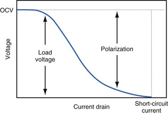
The open-circuit voltage of a battery can be calculated from the thermodynamic free energy for the discharge reaction. This is the voltage that will be measured when there are no kinetic limitations, a condition that occurs only when an insignificant amount of current is being drawn from the battery. With the onset of current flow, the voltage at the battery terminals will be smaller than the open-circuit value. Both chemistry and battery design determine the relationship between voltage and current drawn from the battery. For example, a lead-acid battery for automotive use is constructed of very conductive materials and is designed with large-surface-area electrodes so that extremely high currents can be drawn from it to run an engine’s starter motor. On the other hand, a transistor radio battery is designed with small electrodes because relatively low currents are typically needed to power small portable electronic devices. Figure 6-2 shows a typical current-voltage relationship in which the load voltage approaches the open-circuit voltage (OCV) as the current approaches zero. At the other extreme, the maximum (short-circuit) current is observed when the load voltage approaches zero.
Non-Ideal Battery Behavior
Polarization
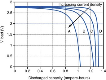
Polarization is any process that causes the voltage at the terminals of a battery to drop below its open-circuit value when it is providing current. The internal resistance of the battery is one important cause. This is well illustrated in Figure 6-3 for the lithium/iodine battery, but the same is true for all batteries to some degree. The differences in the curves for discharge voltage versus capacity at four rates of constant current discharge are mainly caused by the voltage drop associated with internal resistance of the battery. Other contributing elements of voltage loss when a battery provides current are concentration polarization, which is associated with concentration gradients that may develop in the electrolyte or the active electrode materials, and activation polarization, which is associated with the kinetics of the electron-transfer reactions at the electrode/electrolyte interfaces.
Self-Discharge
Self-discharge is the spontaneous discharge of a cell or battery by an internal chemical reaction rather than through useful electrochemical discharge. We have all seen the effects of self-discharge, such as the flashlight that does not work when needed after prolonged storage. One mechanism of self-discharge involves a slow, direct reaction between the anode and cathode; for example, if one or both of the active electrode materials are slightly soluble in the electrolyte. Other self-discharge processes may involve reactions between anode or cathode and another substance in the battery, such as the solvent in the electrolyte; for example, the typical reaction between the anode and the electrolyte solvent to form a passive film on the lithium anode or a gas that pressurizes the battery case. These parasitic reactions are usually very slow, but because medical batteries are expected to operate for many years, their accumulated effects can be appreciable. Although it is difficult to measure the very slow rate of self-discharge reactions, techniques such as microcalorimetry can detect the small amounts of heat involved.7,8 The heat generated can be used to calculate the rate of self-discharge by applying thermodynamic principles. Accurate assessment of self-discharge is an important element in predictive models of battery performance used in both device design and longevity estimation.
Batteries in Implantable Cardiac Rhythm Management Devices
Size, Energy Density, and Current Drain
The relationship between battery size and average current is not one of direct proportionality. For example, decreasing the average current by 50% will not permit a 50% reduction in battery size without compromising longevity because of the inactive materials in a battery (e.g., case, electrolyte, current collectors). Likewise, the usable energy density is also a function of the current demand on the cell. As the current from the cell is increased, the resulting voltage drops significantly (see Fig. 6-3), which reduces the time during which the cell can provide current at or above the minimum voltage necessary to operate the electronic circuits. Thus, usable energy density, which is directly proportional to the area under the discharge (voltage vs. capacity) curve, is also reduced. For very-high-rate batteries such as those used to power ICDs, this is not such an issue because their internal resistance is extremely low.
The Battery and Longevity of Pulse Generator

Effect of Pulse Width on Pacing Current
Increasing the pacing rate, pulse width, or pulse amplitude increases the average pacing current. The average pacing current, excluding static current, is directly proportional to the pacing rate. Recall that the pacing pulse results from the discharge of a capacitor through the electrode-heart interface. This capacitor produces a pulse in which the current decays exponentially with time, as shown for two different pulse widths in Figure 6-4.
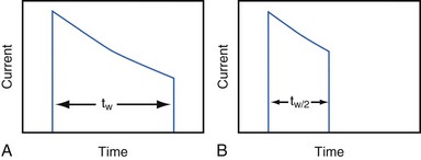
where VA is the amplitude at the beginning of the pacing pulse, RH is the impedance of the lead plus the heart (discussed later), C is the value of the capacitor that delivers the pacing pulse, and t is the time since the beginning of the pacing pulse. In Figure 6-4, A and B, the pulse width is tw and tw/2, respectively. The area under each current-time curve gives the total charge delivered during the pulse. Although the width of the pulse in B is half that of the pulse in A, the charge delivered by this pulse is considerably more than half that of the longer pulse. The exact ratio of the charge delivered in the two cases depends on the values of RH and C. Nevertheless, reducing the pulse width by a given fraction will always reduce the average pacing current by a substantially smaller fraction because of the exponentially decaying shape of the pacing stimulus current curve.
Effect of Lead Impedance on Pacing Current
It is also important to consider the effect of RH on the average pacing current. RH is sometimes called “lead impedance,” but this is a misnomer. The impedance of the lead, itself, is mainly a resistance and it is relatively small (50-100 ohms). Most of the “lead” impedance actually arises at the electrode-tissue interface (500-1000 ohms or more). The factors affecting the impedance of this interface are discussed in Chapter 1. In general, the average pacing current is approximately inversely proportional to the sum of the actual lead and tissue interface impedances. Thus, there is a substantial interest in technologies that can increase RH at the electrode-tissue interface (without increasing the lead conductor resistance), thereby decreasing the pacing current while maintaining a constant or even reduced pacing threshold voltage.
Battery End-of-Service Indication
Methods for Monitoring State of Battery Discharge
Battery Voltage
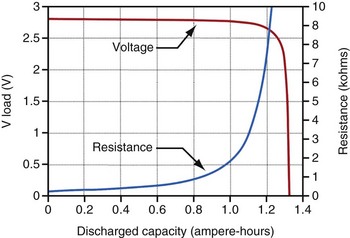
For lithium/iodine batteries, the battery voltage remains relatively constant throughout most of its discharge under low load conditions, as shown in the voltage versus capacity curve in Figure 6-5. This figure also shows the resistance of this battery as it discharges. Note that the resistance changes from a modest value at the beginning of service to a quite large value when it is almost depleted.
Battery Impedance
Battery impedance is another parameter used to signal the elective replacement point. Battery impedance is generally much less dependent on current than battery voltage and may convey more information about the battery’s state of discharge. For example, although the voltage of an Li/I2 battery remains relatively constant through most of its discharge, its impedance increases continuously, and especially rapidly as the battery approaches depletion (see Fig. 6-5). At depletion, battery impedance is not only useful for signaling the elective replacement point but may also provide an estimate of remaining service life. This feature has been incorporated into some pacemaker designs. Battery impedance is usually determined from the open-circuit and load-circuit voltages (or two different load-circuit voltages) of the battery by measuring the voltage drop across a known resistor within the pulse generator, then assuming Ohm’s law can be applied.
Clinical Indicators of Battery Replacement Time
Battery Chemistries Used in Pacemakers
Lithium/Iodine Battery
The lithium/iodine battery is probably the most well known implantable battery because it has been used in the vast majority of cardiac pacemakers. The first implant of a pacemaker powered by an Li/I2 occurred in 1972.5,6,9 At least 13 million Li/I2-powered pacemakers have now been implanted. Many factors favor the use of this battery system. When the current demand is low, it is difficult to improve on the performance of Li/I2 batteries; their high energy density and low rate of self-discharge result in good longevity and small size. The inherently high impedance of the Li/I2 battery has not been a major disadvantage up to now because the current required by modern pacemaker circuits is low, typically about 10 µA. Note that the much larger current delivered during a (short duration) pacing pulse is drawn from a capacitor, which can charge between pacing pulses. The voltage and impedance characteristics of the Li/I2 cell also allow the clinician to monitor the approaching end-of-service indication. This battery system is simple, elegant in concept and is inherently resistant to many common modes of failure, as will be discussed below. As a result, Li/I2 batteries have attained a record of reliability unsurpassed among electrochemical power sources.
Cell Structure
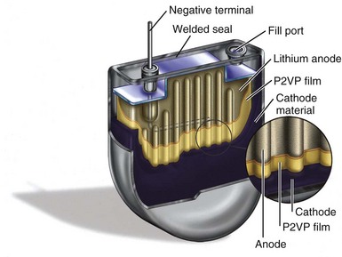
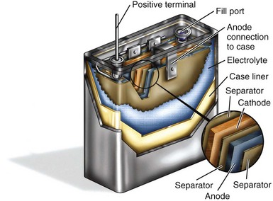
Figure 6-6 shows a cutaway view of a typical Li/I2 battery. In general, Li/I2 batteries have a single, central lithium anode that is surrounded by cathode material, which is at least 96% iodine and has been thermally reacted with a polymer material to render a conductive mixture. The central anode is seen with an embedded current collector wire, and the iodine cathode fills much of the volume inside the battery. Figure 6-6 also shows several other important structures, including the electrical feedthrough that connects the anode to the outside of the cell. The case serves as the site of the electrical connection to the cathode, which is in direct contact with the inside of the container. Another visible feature is the fill port, the means by which the cathode mixture is introduced into the cell, after which the fill port is hermetically sealed.
Discharge Curve
Figure 6-5 shows the characteristic shapes of the voltage and resistance curves as a function of discharge for a typical Li/I2 battery. During most of the battery life, the voltage is stable near 2.8 V, and the resistance change is gradual and dominated by the growing electrolyte (LiI) thickness. Near the end of battery life, the cathode resistance rapidly dominates the resistance of the cell, as the cathode becomes lower in iodine content and less conductive. The region of discharge dominated by cathode resistance and declining cell voltage is used to signal the approaching “end of service” for most pacemakers powered by Li/I2 batteries.10
Effects of Current Drain on Deliverable Capacity
Unfortunately, the high energy density of the Li/I2 battery may be negated if the application requires frequent periods of high current drain. This is caused by the high internal resistance of the battery, which results in voltage losses due to polarization (see Figs. 6-2 and 6-3). The Li/I2 battery system provided small, simple, highly reliable power sources with power characteristics almost ideally suited to the requirements of cardiac pacing for more than 3 decades. In the late 1990s, however, several device features that required higher power began to emerge. In many cases, these peak power requirements are beyond the capability of Li/I2 batteries. These new features include increased use of addressable memory to capture and store information about the electrical activity of the heart, the need for faster and longer-range telemetry to transmit this information outside the body, new physiologic sensors, and new therapies with higher power requirements, such as cardiac resynchronization and treatment of atrial fibrillation. These higher-power features are now being supported by new battery chemistries with similar energy density to lithium/iodine, but a much higher power capability.
Lithium/Carbon Monofluoride Battery
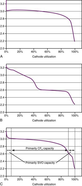
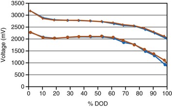
Lithium/carbon monofluoride (Li/CFx) batteries were introduced in commercial coin-type batteries in 1976. Carbon monofluoride (also known as CFx) is a cathode material with very high capacity and moderate power capability. The CFx material is a powder that is mixed with carbon as a conductivity enhancer plus a polymer binder and then pressed into a porous pellet. The battery comprises of a lithium anode, porous polymer separator material, and porous pressed-powder cathode pellet that are inserted into a case and hermetically sealed, similar to an Li/I2 battery. In contrast to the Li/I2 battery, however, the Li/CFx battery uses a liquid electrolyte composed of a lithium salt dissolved in an organic solvent (or solvent mixture). The energy density of this battery is similar to that of the Li/I2 battery, but it delivers significantly higher power. A typical discharge curve is shown in Figure 6-7, A.
Lithium/Hybrid Cathode Battery
New lithium battery chemistry with a cathode consisting of silver vanadium oxide (SVO) plus CFx has been developed to meet the needs of implantable devices with higher rate therapies and features.11,12 SVO has high power capability and is the same cathode material used to power ICDs. As previously described, CFx has modest power capability and more abrupt end-of-service characteristics, but a very high capacity. The blend of the two cathode materials, called a hybrid cathode, yields a primary battery that has an energy density equal to that of a lithium/iodine battery with approximately 100 times more power capability. It can support the new device features and also has good end-of-service detection because of the SVO. Hybrid cathode batteries have been used in implantable cardiac devices since 1999. Cumulative implants through 2009 total about 300,000.
Plots of voltage versus percent of discharged capacity for SVO and CFx batteries are shown in Figure 6-7, A and B. The voltage curve of hybrid cathode behaves like a superposition of the two in proportion to the starting composition of the mixture (Fig. 6-7, C).
Two basic hybrid cathode battery designs have been used in implantable pacemakers. Both types use lithium anodes, a porous polymer separator, a porous pressed-powder cathode pellet, and a liquid electrolyte of lithium salt dissolved in an organic solvent blend. The differences in the two designs are related to the construction of the cathode pellet, either a mixture of the SVO and CFx active materials or the CFx and SVO in separate layers, with the SVO layer adjacent to the lithium anode. In both cases the cathodes also contain a polymer binder and carbon as a conductivity enhancer. Although the methods of construction are different, the discharge behavior of either design is similar to that in Figure 6-7, C.
Battery Chemistries Used in Defibrillators
Comparison of Pacemaker and Defibrillator Batteries
The high power required of defibrillator batteries dictates a different design than used for pacemaker batteries. Figure 6-6 shows a cutaway view of a typical battery used to power a pacemaker, with small and rather thick electrodes. Contrast this with Figure 6-8, which shows an analogous cutaway for a typical defibrillator battery, with very different construction. The long, thin anode and cathode, with two layers of separator film in between, are rolled into a flattened coil. Alternatively, either or both of the electrodes of ICD batteries can be individual flat-plate electrodes electrically connected to each other. Either method provides the high-power electrode area necessary for ICD batteries. The electrolyte in the defibrillator battery is a highly conductive solution of a lithium salt in organic solvents. The design with large, thin electrodes and liquid electrolyte gives the defibrillator battery the high power needed for quickly charging the high-voltage capacitors in the defibrillator. As mentioned, however, these same characteristics also reduce the energy density of the battery.
Types of Batteries Used in Icds
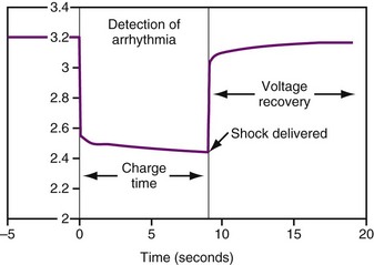
Three different types of battery chemistries are in use currently in ICDs: lithium/silver vanadium oxide, lithium/manganese dioxide, and lithium/layered SVO-CFx (also called “dual cathode”). The shapes of the discharge curves, resistance of the battery, and effects of time since implant vary among battery types. Regardless of the battery chemistry, all ICD batteries are used in much the same way. Most of the time the battery delivers a low current drain as required for sensing and pacing, which has negligible effect on the battery voltage. When it is necessary to charge the high-voltage capacitors, whether for capacitor formation (see Capacitors) or to deliver a therapeutic shock, the voltage drops quickly by about 1 V, then, after the capacitors are charged, recovers quickly to near the previous value (Fig. 6-9).
Lithium/Silver Vanadium Oxide
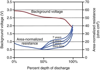
The first ICD battery chemistry put into widespread use was Li/SVO.11–17 These batteries have a distinctive discharge curve, with a slightly sloping voltage at about 3 V in the first third of discharge, followed by a decline in voltage to a flat region with about 2.6 V, and ending in a short region of declining voltage, as seen in Figure 6-10. The uppermost curve represents the battery voltage during normal sensing and bradycardia pacing operations (also called the “background” voltage). It is this background voltage that is typically monitored by the ICD and reported via telemetry. The “load” voltage is the voltage measured during charging of the defibrillation capacitors, and it is typically much lower than the background voltage.
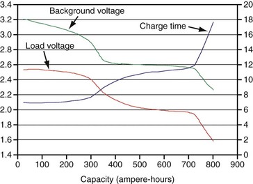
Figure 6-10 Typical plot of discharge characteristics of the lithium/silver vanadium oxide ICD battery.
After many years of laboratory testing and experience in the field, it is apparent that the performance of Li/SVO batteries depends on how rapidly the battery is depleted. When the battery is depleted over a longer period, its internal impedance is higher in the latter half of the discharge curve. Figure 6-11 illustrates this phenomenon, with background voltage and internal impedance of Li/SVO batteries discharged over 3, 5, and 7 years. The internal impedance is unaffected by the discharge rate until midway through discharge. After that point the internal impedance always increases, but to a larger degree for slower discharge rates (i.e., longer discharge times). The higher internal resistance results in longer charge times, especially for the longest discharge periods.
Charge Time–Optimized Li/SVO ICD Batteries
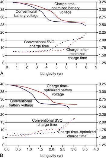
Figure 6-12 compares the voltage and charge time of conventional SVO ICD batteries with charge time–optimized batteries that occupy the same volume in an ICD. For example, when discharged over 7 years, the charge time is considerably lower starting after 4 years for the charge time–optimized battery than the conventionally balanced battery (Fig. 6-12, A). The charge time–optimized battery maintains a much lower charge time in the latter half of ICD life, without substantially sacrificing longevity.18 The difference in charge time is much less when the battery is depleted over a shorter time, such as 3 years (Fig. 6-12, B).
Lithium/Manganese Dioxide
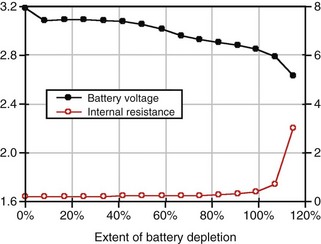
Another ICD manufacturer uses manganese dioxide batteries for use in ICDs. Lithium/manganese dioxide (Li/MnO2) batteries have been used in consumer and military batteries since the 1980s. For example, high-power Li/MnO2 batteries used for photoflash applications have similar electrical characteristics to those used in ICDs. Figure 6-13 provides a graph of Li/MnO2 battery performance. During the first half of battery life, the voltage remains almost constant at 3.1 V. In the second half of battery life, the voltage gradually slopes downward. This characteristic of the battery voltage, along with charge time and the amount of battery energy consumed, allows the clinician to judge how much longer the battery may last. The internal resistance and thus the charge time of Li/MnO2 batteries remain relatively constant until battery replacement is indicated by the ICD.19
Lithium/Layered Silver Vanadium Oxide–Carbon Monofluoride
Another manufacturer of ICD batteries has combined the properties of two cathode materials, silver vanadium oxide and carbon monofluoride, to create a novel ICD battery that exploits the best features of those two materials. SVO provides high power while CFx contributes high capacity per unit volume. The construction of the cathode portion of the battery is rather complex, with a central CFx cathode sandwiched between two metallic current collectors, with SVO electrodes on each side. This arrangement of electrodes allows the SVO, which can discharge at very high rates, to be preferentially discharged when high current is needed to charge the capacitors. Over time the extra lithium ions that accumulate in the SVO part of the electrode equalize with the CFx part, so that the lithium ions become distributed equally within both parts of the cathode. The voltage curve starts at about 3.2 V, stays almost flat from about 20% to 50%, and then gradually declines. Figure 6-14 shows a typical discharge curve.20
 Emerging Power Sources
Rechargeable Lithium-Ion Batteries
Possible modes of lithium-ion battery application include the following:
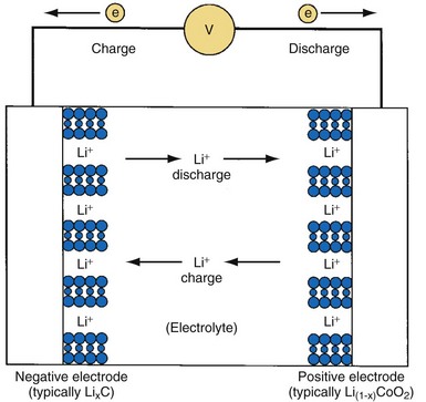
Principles of Operation
The defining feature of a lithium-ion battery is that it contains no metallic lithium. Instead, lithium ions (Li+) are shuttled back and forth between the positive and negative electrodes during charge and discharge, as shown in Figure 6-15. The most common electrode materials are lithium cobalt oxide (LiCoO2) for the positive cathode material and a graphitic carbon to contain the intercalated lithium for the negative anode material. Many alternative materials are being developed and introduced in commercial batteries and will eventually migrate to batteries for implantable medical devices. The general cell construction is similar to that shown for the Li/SVO battery. However, lithium-ion batteries are manufactured in their discharged state (e.g., using LiCoO2 and graphite) and then charged (or “formed”) after the cell is fully assembled.
End of Service Life
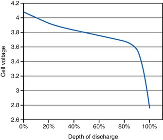
Lithium-ion batteries typically exhibit a gradually declining voltage during discharge that can be used as a “gas gauge” to indicate the state of discharge at a given time (Fig. 6-16). Information about the voltage can be telemetered to a patient controller or a monitor to alert the patient of the need to recharge the battery. However, the end of service for a device powered by a lithium-ion battery is not as readily apparent as for one powered by a primary battery. Because the lithium-ion battery slowly loses capacity as a function of both time and the total number of charge/discharge cycles, the patient may eventually experience a reduced interval between recharge sessions becomes too short to be acceptable to the patient. However, because rechargeable batteries can, in principle, provide unlimited energy, the eventual end of service may be determined by the lifetime of some other component of the implanted device.
Capacitors
Capacitance

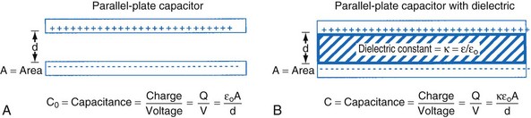
The simplest model of a capacitor is shown in Figure 6-17, A, in which the plates are separated in a vacuum. The conductors (or electrodes) consist of two parallel plates of area (A) separated by a distance (d). The capacitance, or ability to store charge as a function of voltage, is equal to A/d multiplied by a fundamental constant, ε0, the permittivity of free space, which is related to the energy required to separate charge in a vacuum. The value of the capacitance can be increased by inserting insulating materials, known as dielectrics, between the electrodes. The factor by which these materials increase the capacitance is called the dielectric constant, k, which is the ratio of the permittivity of the material to the permittivity of free space, ε/ε0. A simple capacitor containing a dielectric material is shown in Figure 6-17, B. Various materials are used as dielectrics the properties of which largely determine the properties of the capacitor.
Energy Delivery
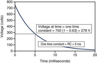
When an ideal capacitor is discharged through a constant resistance, R, the voltage decays with time in an exponential manner, as seen in Figure 6-18. For an ideal capacitor discharged to 0 volts, the delivered energy would equal the stored energy. In ICDs the amount of energy delivered from the capacitor is less than the amount stored. One reason is that the therapy delivery is truncated before the capacitor is completely discharged, and the remaining energy is discarded. A truncated waveform is used because it defibrillates the heart more effectively than a waveform that is allowed to decay to 0 V, despite less energy being delivered to the heart. Other inefficiencies associated with the capacitor, device circuit, and delivery system also reduce the amount of stored energy delivered to the heart, as discussed later.
ICD Capacitor Types
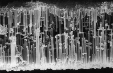
The defibrillation capacitors used in past and current ICDs are called electrolytic capacitors, most often based on aluminum or tantalum electrode materials. The metal electrode materials are processed so they have a very large surface area, which allows for a high capacitance. For aluminum electrolytic capacitors, the positive electrode (anode in a capacitor) starts as a thin foil that has been etched to create a large number of tunnels. Figure 6-19 shows a scanning electron micrograph of a cross section of a highly etched anode foil. For tantalum electrolytic capacitors, the anode is made from tantalum metal powder pressed into a porous pellet and heated to a high enough temperature to make the metal particles bond to one another (called sintering) while still remaining porous. For either material, an oxide film is electrochemically grown (called forming) on the exposed surfaces of the metal electrode. The oxide serves as the capacitor dielectric. Aluminum anodes are typically formed to support charging to about 400 V. Two capacitors are connected in series in the ICD to provide sufficient voltage for defibrillation. Tantalum anodes are typically formed to support charging to 175 to 250 V with three or four capacitors connected in series.
ICD Capacitor Construction
Early ICD devices used commercially produced, cylindrically wound, aluminum electrolytic capacitors developed for flash photography applications. The need for smaller, thinner capacitors and specialized shapes led ICD manufacturers to develop stacked-plate aluminum electrolytic capacitors and custom tantalum electrolytic capacitors.21,22
Cylindrical Aluminum Electrolytic Construction
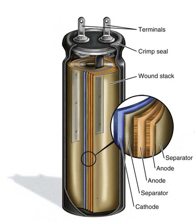
Most commercially produced aluminum electrolytic capacitors employ wound electrodes in a cylindrical shape. Strips of anode and cathode foil, spaced apart by a paper separator, are wound into a coil. Figure 6-20 shows a cutaway view of an aluminum electrolytic photoflash capacitor of the type typically used in the first few generations of ICDs.
Stacked-plate Aluminum Electrolytic Construction
ICD manufacturers have developed stacked-plate aluminum electrolytic capacitor technology to improve the energy density, minimize the thickness, and allow a variety of shapes compared with cylindrically wound capacitors. The details of construction vary among manufacturers, but several design themes are common. Foils and separators are cut to a specific geometry and layered such that multiple anode plates are sandwiched between cathodes and layers of porous separator paper. The geometry of the plates is selected so that the finished capacitor fits efficiently in the ICD. The energy density of stacked-plate capacitors can approach 4 J/cc versus the 2.5 J/cc typical of the coiled configuration. Figure 6-21 shows a cutaway view of a stacked-plate aluminum electrolytic capacitor similar to those used in current ICDs.
Tantalum Electrolytic Capacitor Construction
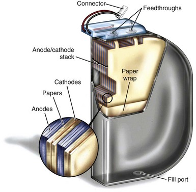
Tantalum electrolytic capacitors have the same basic elements as aluminum electrolytic capacitors. In tantalum capacitors the anode is made using pressed, sintered, and formed tantalum pellet. The cathode in a tantalum capacitor is typically deposited directly on the inside of the capacitor case, making it the negative terminal of the capacitor. Tantalum capacitors have similar benefits to stacked-plate aluminum capacitors but provide higher energy and simpler construction than aluminum capacitors. Rather than layered anode foils, tantalum capacitors have a single anode pellet. The simple and efficient construction minimizes the volume of materials that do not contribute to energy storage (cathode, separator, encasement), thus maximizing energy density. Tantalum capacitors used in current ICDs have an energy density of 5 J/cc or more. The primary drawback of tantalum capacitors is their mass. Because tantalum is very dense, tantalum capacitors are approximately 50% heavier than aluminum capacitors with equivalent energy. Figure 6-22 shows a cutaway view of a tantalum electrolytic capacitor similar to those used in some current ICDs.
Non-Ideal Behavior in Capacitors
Deformation
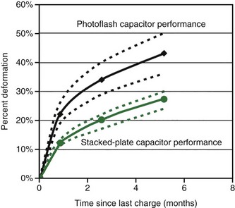
The non-ideal process that is most apparent is called deformation. As previously explained, the dielectric material in electrolytic capacitors is created by “forming,” immediately after which the dielectric is almost free of defects. Over time, the chemical environment within the capacitor or relaxation of residual stress will cause microscopic imperfections in the oxide film on the anode. When the capacitor is charged to a high voltage after a long period of disuse, additional energy is required to regrow oxide in these areas to heal the defects.23 This process is known as re-formation. The additional energy needed to re-form the dielectric results in longer charge times in ICDs. In a typical aluminum capacitor, 25% or more additional energy (and time) may be required to charge the capacitor if it has been many months since the last charge. The amount of additional energy drops to about 15% for capacitors not charged for about a month. Tantalum capacitors perform similarly, although the rate of deformation may be somewhat slower. Figure 6-23 shows capacitor deformation in typical aluminum capacitors for various charging intervals.
 Effects of Batteries and Capacitors on Defibrillation Performance
1 Brennen KR, Fester KE, Owens BB, Untereker DF. Pacemaker battery capacity: a consideration of the manufacturer’s problem. Proceedings of the VIth World Symposium on Cardiac Pacing. Montreal: Pacesymp; 1979.
2 Brennen KR, Fester KE, Owens BB, Untereker DF. A capacity rating system for cardiac pacemaker batteries. J Power Sources. 1980;5:25.
3 Broadhead J. Electrochemical principles and reactions. In Linden D, editor: Handbook of batteries and fuel cells, ed 2, New York: McGraw-Hill, 1994.
4 Holmes CF. An approach to the reliability of implantable lithium batteries. J Power Sources. 1989;26:185.
5 Schmidt CL, Skarstad PM. Impedance behavior in lithium iodine batteries. In: Abraham KM, Solomon M, editors. Proceedings of the Symposium on Primary and Secondary Lithium Batteries, PV91 3. Electrochemical Society; 1991:75-85.
6 Schmidt CL, Skarstad PM. Development of a physically based model for the lithium iodine battery. In: Keily T, Baxter BW, editors. Power sources 13. Leatherhead, England: International Power Sources Committee; 1991:347-361.
7 Untereker DF, Owens BB. Microcalorimetry: a tool for the assessment of self-discharge processes in batteries. Gaithersburg, Md: National Bureau of Standards Workshop; 1977.
8 Untereker DF. The use of a microcalorimeter for analysis of load dependent processes occurring in a primary battery. J Electrochem Soc. 1978;125:1907.
9 Owens BB, editor. Batteries for implantable biomedical devices. New York: Plenum, 1986.
10 Antonioli G, Baggioni F, Consiglio F, et al. Stimulatore cardiaco implantible con nuova battaria a sato solido al litio. Minerva Med. 1973;64:2298.
11 Weiss DJ, Cretzmeyer JW, Crespi AM, et al. Electrochemical cells with end-of-service indicator. US Patent. 1993;5:180. 642
12 Schmidt CL, Skarstad PM. The future of lithium and lithium-ion batteries in implantable medical devices. J Power Sources. 2001;97/98:742-746.
13 Takeuchi ES, Quattrini JP. Batteries for implantable defibrillators. Med Electronics. 1989;119:114-117.
14 Liang CC, Bolster E, Murphy RM: Metal oxide cathode material for high energy density batteries. US Patents 4:310, 609_1982 and 4,391,729_1983.
15 Holmes CF, Keister P, Takeuchi E. High rate lithium solid cathode battery for implantable medical devices. Prog Batteries Solar Cells. 1987;6:64.
16 Crespi AM. Silver vanadium oxide cathode material and method of preparation. US Patent. 1993;5:221. 453
17 Crespi A, Schmidt C, Norton J, et al. Modeling and characteristics of the resistance of lithium/SVO batteries for implantable cardioverter defibrillators. J Electrochem Soc.. 2001;148:A30-A37.
18 Medtronic. Tachyarrhythmia technical concept paper. Vol V, No 1. Marquis ICD Battery Technology.
19 Root MJ. Lithium-manganese dioxide cells for implantable defibrillator devices: discharge voltage models. J Power Sources 2008. 2009;12:083. doi:10.1016/j.jpowsour
20 Gan H, Rubino RS, Takeuchi ES. Dual-chemistry cathode system for high-rate pulse applications. J Power Sources. 2005;146:101-106.
21 Strange TF, Graham TV. Beyond photoflash; development of a polyanode capacitor. CARTS 2000, Huntington Beach, Calif. Proceedings of the 20th Capacitor and Resistor Technology Symposium. 16-21:2000.
22 Breyen MD, Rorvick AW, Skarstad PM. Efficiently packaged aluminum electrolytic capacitors for implantable cardioverter-defibrillators. CARTS 2002, New Orleans. Proceedings of the 22nd Capacitor and Resistor Technology Symposium. 197-202:2002.
23 Norton J, Anderson C. Energy management in aluminum electrolytic capacitors. CARTS 2003, Scottsdale, Ariz. Proceedings of the 23rd Capacitor and Resistor Technology Symposium. 269-277:2003.