CHAPTER 299 Posterior Subaxial and Cervicothoracic Instrumentation
The posterior approach to cervical spine instrumentation was pioneered by B. E. Hadra in 1891 when he wrapped loops of silver wire around the spinous processes of the cervical spine for stabilization.1 Hadra treated chronic fractures, kyphotic deformities, and Pott’s disease with this technique. Fusion of the cervical spine was first described in 1911 by Hibbs and Albee in independent publications.2,3 Hibbs’ method of stripping the periosteum from spinous processes, detaching them from the laminae, and placing them in direct contact with a decorticated surface established the ultimate goal of spinal fusion surgery—solid bony arthrodesis. Today, techniques of posterior cervical instrumentation have advanced considerably from simple wiring of the spinous processes to constructs that impart immediate stability to the cervical spine. Despite technologic advances, bony fusion is still the end goal of instrumentation in the majority of cases, with the hardware serving to stabilize the spine and promote fusion.
Indications
The goal of posterior cervical spine instrumentation is to provide immediate stability, promote fusion, prevent neurological compromise, and allow early mobilization of the patient. Cervical instability is the primary indication for posterior instrumentation of the subaxial cervical spine. Instability has been defined as loss of the ability of the spine, under physiologic loading, to maintain its displacement pattern and prevent increased deformity or neurological deficit (or both).4 Therefore, injury to or destruction of the bony structures or ligaments may introduce instability. This description includes anatomic alterations that occur as a result of operative decompression. Such alterations and their resultant effects on stability must be taken into account when considering the placement of instrumentation. Frequently, fusion and instrumentation are indicated preemptively to treat anticipated postoperative instability or to prevent anticipated postoperative deformity. Fusion with concurrent instrumentation may be required as part of the treatment of a variety of disease processes, including trauma, degenerative disease, congenital anomalies, neoplasm, infection, or inflammatory conditions such as rheumatoid arthritis or ankylosing spondylitis.
Anatomy/Exposure
Dissection should begin in the midline over the level of intended fusion and continue through the nuchal fascia while being careful to stay in the relatively avascular midline raphe. Subperiosteal dissection of the spinous processes, laminae, facets, and lateral masses to their lateral edges should be performed. Interspinous ligaments should be left intact when possible, as well as the muscular attachments and nuchal ligament to C2. It has been suggested that exposure of the C7 transverse processes aids in identification of the entry point for placement of pedicle screws.5
The nerve root exits the neural foramen at the anterolateral aspect of the superior facet.6 Viewed from a posterior exposure, the nerve root is located at the level of the articular line.7 The vertebral arteries are directly anterior to the depression formed between the posterior surface of the lateral mass and the lamina.7 The pedicle forms a bridge from the posterolateral portion of the vertebral body to the anteromedial aspect of the lateral mass, midway between the superior and inferior articular surfaces. The mean mediolateral pedicle angle, measured from the midline sagittal plane, ranges from 39 degrees at C2 to a maximum of 48 degrees at C4 and C5. The mean width of the pedicle measured from the outer cortices ranges from 4.8 mm at C3 to 6.9 mm at C7.8
Techniques of Instrumentation
The bony posterior elements that are available to anchor instrumentation include the spinous processes, laminae, facets, and lateral masses, depending on the patient’s anatomy and pathology. The pedicles are also available for instrumentation, although the small diameter of the C3, C4, and C5 pedicles frequently precludes safe screw placement.8 The individual patient’s pathology, the suitability of the bony structures to accept hardware, the biomechanics of each construct, and the surgeon’s experience should be considered when selecting the method of instrumentation.
Interspinous Wiring
Interspinous wiring is technically simple to perform and generally safe, with minimal risk to the neural elements. Limitations include the necessity of having intact posterior elements for fixation and the occasional necessity of incorporation of uninjured segments into the construct for adequate stabilization. Osteopenic bone is not well suited to this technique secondary to focal forces exerted by wire or cables under tension. Multistranded cables made of stainless steel, titanium, or polyethylene are biomechanically superior to monofilament stainless steel in their ability to resist fatigue.9 Monofilament wire is tightened and secured by twisting, whereas cable is tensioned and crimped according to the manufacturer’s recommendations. Numerous interspinous wiring techniques have been described.
Rogers’ Technique
The Rogers technique may be used for injuries to the posterior ligamentous complex or facet capsule, or both, in the absence of bony injury.10,11 At surgery, a transverse hole is made with a small bur at the base of the spinous processes to be instrumented. Wire or cable is passed through the hole of the superior spinous process, looped around the spinous process superiorly, and then passed back through the hole. The wire is next passed through the hole of the inferior spinous process, looped around the spinous process inferiorly, and then passed back through the hole. The wire or cable is secured under tension. Fusion is achieved with bone graft placed between decorticated laminar surfaces. The procedure is relatively fast and simple to perform and provides a posterior tension band, if needed, to resist flexion forces and to supplement the strength of anterior cervical instrumentation.12
Bohlman’s Triple-Wiring Technique
The Bohlman triple-wiring technique was developed as an evolution of the Rogers interspinous wiring technique to impart greater biomechanical stability.13 First, Rogers’ interspinous wiring is performed. Then, two additional wires are passed through the spinous processes and looped around each respective spinous process, if space permits. Each cable is next passed through corresponding holes in two corticocancellous autologous bone grafts placed on either side of the spinous processes.14 The ends of each wire or cable are then secured under tension (Fig. 299-1).
Dewar’s Technique
Another variation of interspinous wiring is the Dewar procedure (or tension band configuration).15 Two corticocancellous strips of bone are placed on the lateral surfaces of the spinous processes and medial laminae of the vertebrae to be fused. Threaded Kirschner wires (K-wires) are introduced percutaneously to affix the bone grafts to the spinous processes and cut with 1 cm of overhang laterally. Wire is threaded around the K-wires in a Gallie-type fashion. Cervical flexion therefore causes medially directed pressure on the bone graft. The posterior elements must be intact to use this technique.
Facet Wiring
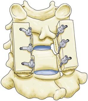
Facet wiring, originally described by Robinson and Southwick,16,17 may be used for unilateral or bilateral facet dislocations or in instances in which the posterior neural arch has been damaged or surgically removed. Holes are drilled in the inferior facet processes at a 90-degree angle relative to the articular surface while protecting the superior facet processes with a Penfield dissector. Wire or cable is then passed through each hole and tightened around longitudinal strut grafts for fusion (Fig. 299-2).
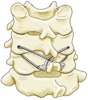
For improved stiffness in axial rotation, Cahill and colleagues introduced a technique wherein the facets are secured to the spinous processes.18 The inferior facet processes are drilled in a fashion similar to that described by Robinson and Southwick, and wire or cable is passed from the facet to the spinous process of the level below (Fig. 299-3). Wire or cable is then wrapped around the spinous process or looped through a hole drilled at the base of the spinous process of the vertebra below. This technique affords improved stiffness in axial rotation over interspinous wiring or the Robinson and Southwick facet wiring technique.
Sublaminar Wiring (Cabling) Techniques
Sublaminar wires have been used extensively for instrumentation of the subaxial cervical spine. Braided cable is the preferred material to use for passing wire into the neural canal because of its increased flexibility and lesser likelihood of being passed anteriorly into the spinal canal.19 Braided cable may be doubled over on itself and the blunt end passed more safely beneath the laminae. After bilateral cable placement, a bone graft is placed in the interspinous space or along the laminar surface and the cable is tightly secured by crimping. Sublaminar wiring has demonstrated stiffness characteristics in flexion and extension and in flexion with fatigue testing similar to Rogers’ and Bohlman’s triple-wiring techniques in a bovine model.20 Placement of sublaminar wires or cables is associated with a 7% risk for neural injury.13,21,22
Sublaminar cables may be used as fixation points for segmental instrumentation. The prototypical device is the Luque rectangle.23 This is a variant of Robinson and Southwick’s facet wiring and consists of a metal rod in the shape of a rectangle that is affixed to the facets in a manner similar to the Robinson and Southwick facet wiring technique. Sublaminar wires are then placed one level cephalad and one level caudal to the levels of fusion and tightened to the horizontal portion of the metal rod. When compared with Robinson and Southwick’s facet wiring technique, this method has improved biomechanical stiffness and decreased range of motion.23,24 It may be used after surgical decompression with laminectomies that span multiple levels.
Lateral Mass Screw Fixation
Lateral mass screw placement was first described by Roy-Camille in 1964 and has undergone numerous refinements since that time.6,7,25–28 Placement of screws in the lateral mass is technically simple, although a potential for neurovascular injury exists because of the proximity of the vertebral artery and cervical nerve root. Careful preoperative consideration of patient anatomy is warranted, especially in those with severe degenerative disease, in whom erosive arthropathy may reduce the size and distort the shape of the lateral masses considerably.
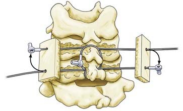
Lateral mass screws were first used with plates for fixation as early as 1979.29 These constructs, however, were constrained by variable patient anatomy and the inability to easily extend existing constructs cranially or caudally.30 Screw and rod–based systems were subsequently developed and allowed easier adaptation to patient anatomy and extension of existing constructs (Fig. 299-4). Although the biomechanics of individual screws is similar to that of screws used in lateral mass plating techniques, the flexibility of screw and rod–based systems allows each to be placed in an optimal location at an optimal trajectory. In addition, many systems permit individual screws to be locked to the rod-based longitudinal element to prevent screw backout. Lateral mass screw-based methods of fixation offer general applicability but are particularly useful in cases in which the spinous processes and laminae are compromised or absent and fixation of the posterior neural arch is not possible with interspinous wiring or other techniques.
The boundaries of the posterior surface of the lateral mass serve as a guide to the screw entry point. These boundaries are the lateral facet edge, the medial facet line, and the articular lines superiorly and inferiorly. Any one of several lateral mass screw placement techniques may be used, each with a different entry point and trajectory. The Roy-Camille method begins with an entry point at the center of the lateral mass.29 The screw is placed with 10 degrees of lateral angulation and 0 degrees of cephalad angulation (Fig. 299-5). The Magerl technique uses an entry point 2 to 3 mm medial and cephalad to the midpoint of the lateral mass.28 The screw is placed with 25 degrees of lateral angulation and a cephalad angulation that is parallel to the articular surface of the facet joint (Fig. 299-5). An and coauthors described a modified technique using an entry point located 1 mm medial to the midpoint of the lateral mass.6 The screw is placed with 30 degrees of lateral angulation and 15 degrees of cephalad angulation. These differences lead to unique risks to the neurovascular structures. Heller and coworkers conducted a study of the trajectories of screws placed by the Magerl and Roy-Camille techniques and found that screws placed by the Roy-Camille technique had a 2% rate of injured nerve roots as opposed to 6% with the Magerl technique. The Roy-Camille technique resulted in a 34% rate of facet joint violation, whereas the Magerl technique resulted in a 0% rate.31
Lateral mass screws ranging in diameter from 2.7 to 4.5 mm may be used. Screws less than 3.2 mm in diameter or larger than 3.5 mm in diameter have lower pullout resistance than do screws within this range.32 The technique of Magerl is associated with higher resistance to pullout, probably because of the ability of the screw to engage a greater length of bone in the lateral mass.33,34 Screw length may be 10 to 16 mm, with 14-mm screws achieving bicortical purchase approximately 92% of the time as reported by Sekhon.26
Fusions supplemented with lateral mass screws and rods or plates are associated with an overall fusion rate of 80% to 95%.25 This figure varies with the indication for fusion. Sekhon reported a 1.4% rate of instrumentation failure and a 2.1% rate of kyphosis with a mean follow-up period of 22 months.26 In a series of 221 patients, Roy-Camille and associates showed 85% without secondary kyphosis, 8.8% with 5 degrees of kyphosis, 3% with 5 to 10 degrees of kyphosis, and 3% with 10 to 20 degrees of kyphosis.7
Failure of lateral mass screw–based instrumentation most commonly occurs at the bone-screw interface.32 The highest pullout resistance occurs at C4, with strength decreasing about 30% at the second and seventh cervical vertebrae because of anatomic variability of the lateral masses. This underscores the need to consider each potential site of fixation carefully in terms of suitability for screw placement.6,8,32,35 Bicortical lateral mass screw purchase offers 28% increased resistance to pullout over unicortical purchase.32 Some authors have opined that bicortical purchase may be dangerous because of the proximity of the nerve root and vertebral artery.36 However, the risk for nerve root injury and vertebral artery injury varies according to the technique used for screw placement. In an in vivo study of 1026 consecutive lateral mass screws placed with a technique similar to An’s (the difference being a cephalad angulation of 20 to 25 degrees instead of 15 degrees), facet joint disruption occurred in 0.8%, 0- to 1-mm breach of the foramen transversarium in 1.9%, greater than 1-mm breach of the foramen transversarium in 0%, breach of the neural foramen in 0%, and breach of the spinal canal in 0%. The screws used were 3.5 mm in diameter in 99.2% and 14 mm in length in 88% and achieved bicortical purchase in 92.4%.26 Additionally, an in vitro study demonstrated that violation of the nerve root was less likely with the An technique than with the Magerl and Anderson techniques.37 Therefore, bicortical screw placement appears to be safe and offers a low incidence of postoperative screw pullout when the An technique is used.
Transpedicular Screws
The technique of transpedicular screw placement in the cervical spine was first described by Abumi and colleagues in 1994.38 Other than at C7, its use is not currently widespread. Insertion is thought to be technically more difficult and associated with more potential risks to neurovascular structures than is insertion of lateral mass screws. Indications include deformity or instability in patients with poor bone quality, particularly those with osteopenia or rheumatoid arthritis and especially if instrumentation spanning several segments is needed. A relative indication for its use is posterior correction of kyphosis and deformity, for which transpedicular screws offer enhanced biomechanical stability and resistance to pullout.39
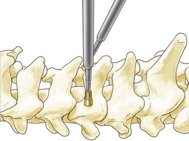
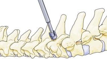
The insertion point for cervical transpedicular screws at C3 to C6 has been described as slightly lateral to midline of the posterior surface of the lateral mass and just inferior to the articular line.38,40 A high-speed bur is used to create the screw entry point, followed by insertion of a pedicle probe under fluoroscopic guidance. The suggested trajectory is 25 to 45 degrees medially in the axial plane and parallel to the superior end plate in the sagittal plane.
Transpedicular screws are placed more frequently at C7 for a variety of reasons. Because the lateral masses of C7 are often unsuitable for placement of lateral mass screws, C7 transpedicular screws are a useful alternative caudal anchor for longer constructs. Second, pullout of lateral mass screws at C7 is more likely when at either the cephalad or caudal end of a construct.41 Finally, placement of C7 transpedicular screws is technically less demanding than in other subaxial cervical vertebrae because the C7 pedicles have a larger mean diameter (5.4 to 9.1 mm) and are relatively remote from the vertebral arteries in the majority of patients.8 The screw entry point for C7 is halfway between the medial facet line and the lateral facet edge in the mediolateral dimension and 1 mm inferior to a horizontal line bisecting the base of the transverse process in the craniocaudal dimension. It has been suggested that for C7 transpedicular screw placement, the base of the transverse processes should be exposed. Alternatively, a limited laminectomy may be performed to palpate the C7 pedicle to aid in accurate screw placement. Once the proper entry point has been located, the cortical surface is perforated with a bur to a depth of 5 mm. The pedicle is then cannulated to an appropriate depth at a medial angulation of 35 to 45 degrees and a caudal angulation of 5 degrees from the inferior end plate of C7 (Fig. 299-6).42 Some authors have suggested that the medial pedicle cortex is stronger than the lateral pedicle cortex and thus the medial wall should be used as a guide to cannulation of the pedicle.5,43
Cervical transpedicular screw insertion is generally safe in studies by experienced groups. In both in vivo and in vitro studies, C4 is found to be the most frequently violated pedicle.5,44 Abumi and coauthors reported that 712 cervical pedicle screws were inserted in 180 patients, with 45 (6.3%) pedicle violations seen on computed tomography (CT). There were 3 neurovascular complications: 2 of the 45 pedicle violations caused radiculopathy and 1 vertebral artery injury occurred without any reported neurological consequence.44 Screw size in this study was 3.5 to 4.5 mm in diameter and 20 to 28 mm in length. Preoperative CT evaluation of individual pedicle anatomy is suggested for each patient.
Laminar Hooks
Laminar hooks may be used as an alternative point of fixation in the posterior cervical spine. The technique for placement is technically simple, but it requires the presence of intact posterior elements and does expose the patient to risk for neural injury because of the presence of the hook in the spinal canal. Cervical hooks, when placed at the caudal end of a lateral mass screw construct, result in similar resistance to flexion-extension, lateral bending, and axial rotation range of motion45 as do bicortical lateral mass screws or pedicle screws. Hooks have higher resistance to pullout than either lateral mass or transpedicular screws if placed properly. Therefore, cervical laminar hooks are a potentially useful alternative method of fixation, particularly in situations in which lateral mass screws, translaminar screws, and transpedicular screws are precluded.
Other Fixation Techniques
The hook plate was designed by Magerl and colleagues in 1979.28 This seldom-used internal fixator may be applied for posterior stabilization over one or two motion segments for diskoligamentous injury not involving the vertebral body. The hook is placed under the lamina of the lowest level, where a notch is made to resist movement. A bone graft is placed in the interspinous space, and the hook is secured at the cephalad level with a lateral mass screw placed according to the technique of Magerl. Tightening of the screw creates axial compression, whereas the bone graft resists extension forces.
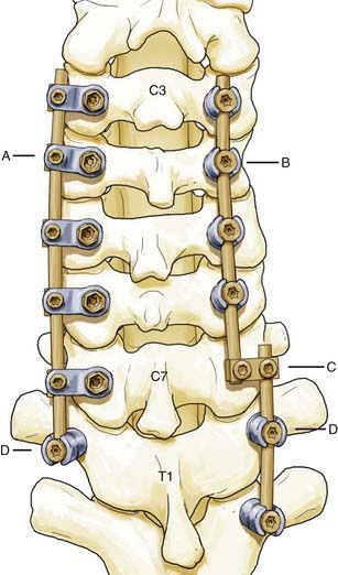
Cervicothoracic Junction
The transition from the mobile, lordotic cervical spine to the stiffer, kyphotic thoracic spine places great demands on instrumentation at the cervicothoracic junction.41,46,47 Crossing the C7-T1 junction can be geometrically challenging, particularly in view of the medial location of the lateral mass screw heads in relation to the transpedicular screw heads. Therefore, flexibility in the surgeon’s armamentarium is very helpful. In-depth knowledge of the capabilities of the instrumentation to be used is essential. Two potential strategies are depicted in Figure 299-4.
Biomechanical Considerations
Gill and associates studied the biomechanics of posterior instrumentation in cadaveric human cervical spines and found no significant difference in stiffness in flexion or extension for any of the following constructs: bicortical lateral mass screws with tubular plates, unicortical lateral mass screws with tubular plates, Rogers’ interspinous wiring, or the Halifax clamp technique.48 The ability of interspinous wiring and Halifax clamp constructs to exhibit stiffness in extension can be explained by the compressive preloading of the posterior element allowed by the construct, which increases friction between the facet joints and limitation of motion in extension. In this study, no fatigue testing of any of the constructs was performed; therefore, the results may not have relevance to clinical settings in which fatigue of the surgical construct is a factor.
Weis and coworkers studied posterior plating with lateral mass screws and the Rogers interspinous wiring technique in fatigue testing of biomechanical models based on cadaveric cervical calf spines,9 a model previously validated by Coe and associates49 and Sutterlin and colleagues.20 Lateral mass screws were placed at 10 degrees of lateral angulation and 30 degrees of cephalad angulation, with bicortical purchase. The authors found that there was significantly greater stiffness in axial rotation when using posterior plating versus interspinous wiring immediately after instrumentation, but no statistical difference in axial range of motion or stiffness with fatigue testing. They also found no difference in flexion-extension range of motion with posterior plating versus interspinous wiring immediately after instrumentation or with fatigue testing. However, there was increased stiffness in flexion and extension with posterior plating on fatigue testing. Stiffness in lateral bending was significantly greater with posterior plating immediately after instrumentation and also with fatigue testing. These results indicate that lateral mass screws with plating (and, by inference, rods with polyaxial screws) have superior stiffness in a clinical scenario involving flexion-extension and lateral bending.
Biomechanically, transpedicular screws may offer some advantages over lateral mass screws. Transpedicular screws have been shown to have higher resistance to hardware pullout than lateral mass screws placed per the technique of An.8 In a separate study, the initial stiffness of pedicle screws versus lateral mass screws was not significant. However, after cyclic loading (fatigue testing), there was significantly higher stiffness in pedicle screw constructs than in lateral mass screw constructs in flexion-extension and lateral bending, but not in axial rotation.50 Transpedicular screws also have increased stiffness in comparison to lateral mass screws when spanning two unstable cervical levels rather than one.51 Additionally, constructs incorporating C7 transpedicular screws have been shown to offer greater stability than those using lateral mass screws at the same level.52
Abdu WA, Bohlman HH. Techniques of subaxial posterior cervical spine fusions: an overview. Orthopedics. 1992;15:287-295.
Abumi K, Itoh H, Taneichi H, et al. Transpedicular screw fixation for traumatic lesions of the middle and lower cervical spine: description of the techniques and preliminary report. J Spinal Disord. 1994;7:19-28.
Abumi K, Kaneda K. Pedicle screw fixation for nontraumatic lesions of the cervical spine. Spine. 1997;22:1853-1863.
Abumi K, Shono Y, Ito M, et al. Complications of pedicle screw fixation in reconstructive surgery of the cervical spine. Spine. 2000;25:962-969.
An HS, Gordin R, Renner K. Anatomic considerations for plate-screw fixation of the cervical spine. Spine. 1991;16:S548-S551.
Bueff HU, Lotz JC, Colliou OK, et al. Instrumentation of the cervicothoracic junction after destabilization. Spine. 1995;20:1789-1792.
Cooper PR, Cohen A, Rosiello A, et al. Posterior stabilization of cervical spine fractures and subluxations using plates and screws. Neurosurgery. 1988;23:300-306.
Espinoza-Larios A, Ames CP, Chamberlain RH, et al. Biomechanical comparison of two-level cervical locking posterior screw/rod and hook/rod techniques. Spine J. 2007;7:194-204.
Heller JG, Carlson GD, Abitbol JJ, et al. Anatomic comparison of the Roy-Camille and Magerl techniques for screw placement in the lower cervical spine. Spine. 1991;16:S552-S557.
Heller JG, Estes BT, Zaouali M, et al. Biomechanical study of screws in the lateral masses: variables affecting pull-out resistance. J Bone Joint Surg Am. 1996;78:1315-1321.
Karaikovic EE, Kunakornsawat S, Daubs MD, et al. Surgical anatomy of the cervical pedicles: landmarks for posterior cervical pedicle entrance localization. J Spinal Disord. 2000;13:63-72.
Karaikovic EE, Yingsakmongkol W, Gaines RWJr. Accuracy of cervical pedicle screw placement using the funnel technique. Spine. 2001;26:2456-2462.
Kotani Y, Cunningham BW, Abumi K, et al. Biomechanical analysis of cervical stabilization systems. An assessment of transpedicular screw fixation in the cervical spine. Spine. 1994;19:2529-2539.
Kothe R, Ruther W, Schneider E, et al. Biomechanical analysis of transpedicular screw fixation in the subaxial cervical spine. Spine. 2004;29:1869-1875.
Maurer PK, Ellenbogen RG, Ecklund J, et al. Cervical spondylotic myelopathy: treatment with posterior decompression and Luque rectangle bone fusion. Neurosurgery. 1991;28:680-683.
Rhee JM, Kraiwattanapong C, Hutton WC. A comparison of pedicle and lateral mass screw construct stiffnesses at the cervicothoracic junction: a biomechanical study. Spine. 2005;30:E636-E640.
Roy-Camille R, Saillant G, Laville C, et al. Treatment of lower cervical spinal injuries—C3 to C7. Spine. 1992;17:S442-S446.
Sutterlin CE3rd, McAfee PC, Warden KE, et al. A biomechanical evaluation of cervical spinal stabilization methods in a bovine model. Static and cyclical loading. Spine. 1988;13:795-802.
White AA3rd, Panjabi MM, editors. Clincal Biomechanics of the Spine. 2nd ed. Philadelphia: JB Lippincott. 1990:722.
Xu R, Haman SP, Ebraheim NA, et al. The anatomic relation of lateral mass screws to the spinal nerves. A comparison of the Magerl, Anderson, and An techniques. Spine. 1999;24:2057-2061.
1 Hadra BE. Wiring of the vertebrae as a means of immobilization in fracture and Potts’ disease. 1891. Clin Orthop Relat Res. 2007;460:11-13.
2 Hibbs RA. An operation for progressive spinal deformities: a preliminary report of three cases from the service of the orthopaedic hospital. 1911. Clin Orthop Relat Res. 2007;460:17-20.
3 Albee FH. Transplantation of a portion of the tibia into the spine for Pott’s disease: a preliminary report 1911. Clin Orthop Relat Res. 2007;460:14-16.
4 White AA3rd, Panjabi MM, editors. Clincal Biomechanics of the Spine. 2nd ed. Philadelphia: JB Lippincott. 1990:722.
5 Karaikovic EE, Yingsakmongkol W, Gaines RWJr. Accuracy of cervical pedicle screw placement using the funnel technique. Spine. 2001;26:2456-2462.
6 An HS, Gordin R, Renner K. Anatomic considerations for plate-screw fixation of the cervical spine. Spine. 1991;16:S548-S551.
7 Roy-Camille R, Saillant G, Laville C, et al. Treatment of lower cervical spinal injuries—C3 to C7. Spine. 1992;17:S442-S446.
8 Jones EL, Heller JG, Silcox DH, et al. Cervical pedicle screws versus lateral mass screws. Anatomic feasibility and biomechanical comparison. Spine. 1997;22:977-982.
9 Weis JC, Cunningham BW, Kanayama M, et al. In vitro biomechanical comparison of multistrand cables with conventional cervical stabilization. Spine. 1996;21:2108-2114.
10 Rogers WA. Treatment of fracture-dislocation of the cervical spine. J Bone Joint Surg. 1942;24:245-258.
11 Rogers WA. Fractures and dislocations of the cervical spine; an end-result study. J Bone Joint Surg Am. 1957;39:341-376.
12 Kim SM, Lim TJ, Paterno J, et al. A biomechanical comparison of three surgical approaches in bilateral subaxial cervical facet dislocation. J Neurosurg Spine. 2004;1:108-115.
13 McAfee PC, Bohlman HH, Wilson WL. The triple wire fixation technique for stabilization of acute fracture-dislocations: a biomechanical analysis. Orthop Trans. 1985;9:142.
14 Abdu WA, Bohlman HH. Techniques of subaxial posterior cervical spine fusions: an overview. Orthopedics. 1992;15:287-295.
15 Davey JR, Rorabeck CH, Bailey SI, et al. A technique of posterior cervical fusion for instability of the cervical spine. Spine. 1985;10:722-728.
16 Robinson RA, Southwick WO. Indications and technics for early stabilization of the neck in some fracture dislocations of the cervical spine. South Med J. 1960;53:565-579.
17 Callahan RA, Johnson RM, Margolis RN, et al. Cervical facet fusion for control of instability following laminectomy. J Bone Joint Surg Am. 1977;59:991-1002.
18 Cahill DW, Bellegarrigue R, Ducker TB. Bilateral facet to spinous process fusion: a new technique for posterior spinal fusion after trauma. Neurosurgery. 1983;13:1-4.
19 Songer MN, Spencer DL, Meyer PRJr, et al. The use of sublaminar cables to replace Luque wires. Spine. 1991;16:S418-S421.
20 Sutterlin CE3rd, McAfee PC, Warden KE, et al. A biomechanical evaluation of cervical spinal stabilization methods in a bovine model. Static and cyclical loading. Spine. 1988;13:795-802.
21 Geremia GK, Kim KS, Cerullo L, et al. Complications of sublaminar wiring. Surg Neurol. 1985;23:629-635.
22 Fraser AB, Sen C, Casden AM, et al. Cervical transdural intramedullary migration of a sublaminar wire. A complication of cervical fixation. Spine. 1994;19:456-459.
23 Maurer PK, Ellenbogen RG, Ecklund J, et al. Cervical spondylotic myelopathy: treatment with posterior decompression and Luque rectangle bone fusion. Neurosurgery. 1991;28:680-683.
24 Cusick JF, Pintar FA, Yoganandan N, et al. Wire fixation techniques of the cervical facets. Spine. 1997;22:970-975.
25 Cooper PR, Cohen A, Rosiello A, et al. Posterior stabilization of cervical spine fractures and subluxations using plates and screws. Neurosurgery. 1988;23:300-306.
26 Sekhon LH. Posterior cervical lateral mass screw fixation: analysis of 1026 consecutive screws in 143 patients. J Spinal Disord Tech. 2005;18:297-303.
27 Nazarian SM, Louis RP. Posterior internal fixation with screw plates in traumatic lesions of the cervical spine. Spine. 1991;16:S64-S71.
28 Jeanneret B, Magerl F, Ward EH, et al. Posterior stabilization of the cervical spine with hook plates. Spine. 1991;16:S56-S63.
29 McKibbin B, editor. Recent Advances in Orthopedics. Edinburgh: Churchill-Livingstone. 1979:57-87.
30 Mummaneni PV, Haid RW, Traynelis VC, et al. Posterior cervical fixation using a new polyaxial screw and rod system: technique and surgical results. Neurosurg Focus. 2002;12(1):E8.
31 Heller JG, Carlson GD, Abitbol JJ, et al. Anatomic comparison of the Roy-Camille and Magerl techniques for screw placement in the lower cervical spine. Spine. 1991;16:S552-S557.
32 Heller JG, Estes BT, Zaouali M, et al. Biomechanical study of screws in the lateral masses: variables affecting pull-out resistance. J Bone Joint Surg Am. 1996;78:1315-1321.
33 Errico T, Uhl R, Cooper P, et al. Pullout strength comparison of two methods of orienting screw insertion in the lateral masses of the bovine cervical spine. J Spinal Disord. 1992;5:459-463.
34 Montesano PX, Jauch E, Jonsson HJr. Anatomic and biomechanical study of posterior cervical spine plate arthrodesis: an evaluation of two different techniques of screw placement. J Spinal Disord. 1992;5:301-305.
35 Heller JG, Silcox DH3rd, Sutterlin CE3rd. Complications of posterior cervical plating. Spine. 1995;20:2442-2448.
36 Jonsson HJr, Rauschning W. Postoperative cervical spine specimens studied with the cryoplaning technique. J Orthop Trauma. 1992;6:1-9.
37 Xu R, Haman SP, Ebraheim NA, et al. The anatomic relation of lateral mass screws to the spinal nerves. A comparison of the Magerl, Anderson, and An techniques. Spine. 1999;24:2057-2061.
38 Abumi K, Itoh H, Taneichi H, et al. Transpedicular screw fixation for traumatic lesions of the middle and lower cervical spine: description of the techniques and preliminary report. J Spinal Disord. 1994;7:19-28.
39 Abumi K, Shono Y, Taneichi H, et al. Correction of cervical kyphosis using pedicle screw fixation systems. Spine. 1999;24:2389-2396.
40 Abumi K, Kaneda K. Pedicle screw fixation for nontraumatic lesions of the cervical spine. Spine. 1997;22:1853-1863.
41 Rhee JM, Kraiwattanapong C, Hutton WC. A comparison of pedicle and lateral mass screw construct stiffnesses at the cervicothoracic junction: a biomechanical study. Spine. 2005;30:E636-E640.
42 Barrey C, Cotton F, Jund J, et al. Transpedicular screwing of the seventh cervical vertebra: anatomical considerations and surgical technique. Surg Radiol Anat. 2003;25:354-360.
43 Karaikovic EE, Kunakornsawat S, Daubs MD, et al. Surgical anatomy of the cervical pedicles: landmarks for posterior cervical pedicle entrance localization. J Spinal Disord. 2000;13:63-72.
44 Abumi K, Shono Y, Ito M, et al. Complications of pedicle screw fixation in reconstructive surgery of the cervical spine. Spine. 2000;25:962-969.
45 Espinoza-Larios A, Ames CP, Chamberlain RH, et al. Biomechanical comparison of two-level cervical locking posterior screw/rod and hook/rod techniques. Spine J. 2007;7:194-204.
46 Delamarter RB, Batzdorf U, Bohlman HH. The C7-T1 junction: problems with diagnosis, visualization, instability, and decompression. Orthop Trans. 1989;13:218.
47 An HS, Vaccaro A, Cotler JM, et al. Spinal disorders at the cervicothoracic junction. Spine. 1994;19:2557-2564.
48 Gill K, Paschal S, Corin J, et al. Posterior plating of the cervical spine. A biomechanical comparison of different posterior fusion techniques. Spine. 1988;13:813-816.
49 Coe JD, Warden KE, Sutterlin CE3rd, et al. Biomechanical evaluation of cervical spinal stabilization methods in a human cadaveric model. Spine. 1989;14:1122-1131.
50 Kothe R, Ruther W, Schneider E, et al. Biomechanical analysis of transpedicular screw fixation in the subaxial cervical spine. Spine. 2004;29:1869-1875.
51 Kotani Y, Cunningham BW, Abumi K, et al. Biomechanical analysis of cervical stabilization systems. An assessment of transpedicular screw fixation in the cervical spine. Spine. 1994;19:2529-2539.
52 Bueff HU, Lotz JC, Colliou OK, et al. Instrumentation of the cervicothoracic junction after destabilization. Spine. 1995;20:1789-1792.