CHAPTER 53 Posterior Dynamic Stabilization*
Degenerative disorders in the lumbar spine can lead to an abnormal pattern of motion causing segmental instability and low back pain, although the precise relationship between instability and low back pain with or without leg pain has not been established. The standard of care for the surgical treatment of degenerative instability causing low back pain has been fusion with or without instrumentation.1 More recent advances in fusion techniques have increased the rate of successful fusion, without an equivalent improvement in relief of pain. The fusion rate with modern technology approaches 100%, but successful pain relief does not exceed 60% to 70%. A solid fusion does not always result in a successful clinical outcome.2,3 A fusion can have long-term effects on unfused segments, leading to accelerated degeneration of the adjacent segments, engendered by abnormal forces and motion at those segments.4,5 Because of these limitations of fusion, dynamic stabilization was introduced in the treatment of activity-related mechanical low back pain.
Instability
The rationale for fusing the painful motion segment has been the concept of instability.6 Understanding and diagnosis of clinical instability remains controversial. When abnormal motion is present on flexion-extension radiographs, especially in the setting of spondylolisthesis, fusion is accepted as a reasonable option.7 By this standard, relatively few patients with low back pain have overt subjective or objective evidence of instability, however. Pope and Panjabi8 suggested that instability is a mechanical entity and is defined as a loss of stiffness to a given load. Biomechanical and radiologic studies using open magnetic resonance imaging (MRI) in flexion and extension have shown, however, that segmental motion either does not change significantly with disc degeneration9–11 or may decrease except during early stages of disc degeneration.12
Mulholland and Sengupta13 suggested that spinal instability does not mean “increased motion” as commonly misunderstood,8,14 but rather it indicates abnormal load distribution across the vertebral endplate. The pathologic changes within the disc space may result in abnormal transmission of load across the endplates. It has been well established in other weight-bearing joints that abnormal load transmissions result in degenerative changes, and the resultant pain may be diminished by a properly placed osteotomy to realign the joint forces and redistribute the loads.15 The normal disc consists of a homogeneous gel of collagen and proteoglycan. The normal disc is isotropic, similar to a fluid-filled bag, a property that allows it to transmit load uniformly across the vertebral endplates.13
Disc degeneration alters the isotropic properties of the disc. The disc becomes nonhomogeneous, with areas of fragmented and condensed collagen, cartilage fragments, fluid, and gas.16 Load transmission over the endplates becomes uneven. The nucleus becomes depressurized, and an increasingly larger load is transmitted through the anulus, which leads to splitting and inward folding of the anulus.17 The central area of the endplate overlying the depressurized nucleus now transmits lesser load, and corresponding endplate changes, such as destruction, thinning of the trabeculae, and thinning of the cartilaginous endplate,18,19 may be noted. Focal loading of the endplate cartilage and subchondral bony trabeculae can occur with certain positions, leading to a sharp increase in back pain. This situation is analogous to a “stone in the shoe” causing high spot loading and pain, a concept proposed by Mulholland and Sengupta.13
This concept explains the clinical sign of instability catch as experienced by patients with mechanical back pain secondary to disc degeneration during flexion-extension movement. This hypothesis also explains why manipulation of the lumbar spine by a chiropractor may occasionally dislodge the fragment from its weight-bearing position, bringing an immediate relief of acute low back pain.13 Mulholland and Sengupta’s hypothesis of abnormal loading as the primary cause of mechanical back pain was supported by a close association of abnormal disc pressure profiles with positive discography with pain provocation.20 A pressure profilometry study by McNally and Adams21 revealed the anisotropic properties of the degenerated disc. This study showed that the pattern of loading, rather than the absolute levels of loading, was related to pain generation in the degenerated spine. The concept may also help explain the lack of correlation between degrees of disc degeneration and back pain because individual anatomic and consequential load transmission changes vary from one person to another. With advancing age, the continued progression of these changes results in the disc becoming more collagenized and homogeneous. The very aged disc may distribute loads more evenly again, resulting in a degree of spontaneous relief of pain with time.22
Panjabi23 described spinal stability in vivo as a function of three subsystems: (1) the spinal column, (2) the spinal muscles, and (3) the neural control unit. In vivo, spinal muscle action and neural control may be equal or more important spinal stabilizers, but the focus of surgical treatment of back pain has been the passive stability provided by the spinal column itself. Instability in the spinal column may result from damage or degeneration of bone, joints, or ligaments, which may be characterized by an increased motion in its early stages. By the time the pain becomes severe enough to consider surgical intervention, the total range of motion is often diminished or abnormal in quality.24 Panjabi23 redefined spinal instability as an abnormal motion often accompanied by an increased neutral zone motion caused by ligament laxity, even when the range of motion is diminished. Panjabi used the analogy of a marble rolling on a soup bowl (Fig. 53–1).
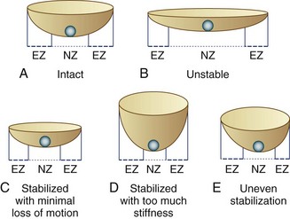
FIGURE 53–1 Panjabi’s23 analogy of a “marble on a soup bowl,” explaining relationship between spinal instability and change in range of motion. A, Intact spine. The marble can move with little resistance across neutral zone (NZ) but faces increasing resistance toward elastic zone (EZ). B, Unstable motion segment. The bowl is flat allowing the marble to move to and fro with little resistance—that is, increased NZ with no increase in EZ. C, Stabilized segment. A smaller cup reduces primarily NZ, with minimal reduction of EZ movement. D, Stabilized segment—but too much loss of motion, which is undesirable. E, Uneven stabilization—with different stiffness in two directions, which is again undesirable.
Definitions
Soft fusion is a newer term that refers to posterior spinal fusion with minimal stiffness. Some biomechanical and clinical studies indicate the rigidity of lumbar fusion may vary depending on fusion techniques.25,26 The theory behind the concept of soft fusion is that intertransverse process fusions using PDS devices may achieve a less rigid fusion compared with conventional rigid fusion with fusion rods or interbody devices and may be less detrimental to the adjacent segment. At this time, there is no clinical evidence supporting the concept of soft fusion. This concept has evolved from the fact that many PDS devices obtain U.S. Food and Drug Administration (FDA) approval under 510K for spinal fusion only and not for nonfusion stabilization. Use of these devices as dynamic stabilization devices without fusion represents off-label use.
Biomechanical Goals for Posterior Dynamic Stabilization
Load Transmission
The mechanism of pain relief with dynamic stabilization may be unloading the disc and the facet joints by load sharing, preventing abnormal load distribution and high spot loading.13 How much load should be shared by the device is unclear. It may be assumed, however, that the device would reduce the intradiscal pressure by the magnitude of load sharing.
Resistance to Fatigue Failure
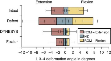
The motion restriction should be uniform throughout the range of motion. If the device may cause too much restriction of motion in any direction, most commonly acting like an extension stop, the device may be exposed to repeatedly unusually high stress in extension and may eventually fail (Fig. 53–2). Similarly, the load sharing should be uniform throughout the range of motion. If the device may unload the disc too much in one direction, often in extension, the device has to bear unusually high load during that motion and is likely to fail (Fig. 53–3).
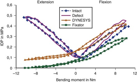
Normally, the disc pressure increases in flexion and extension and is lowest in neutral position. A PDS device ideally should permit an increase in the disc pressure in flexion and extension but to a smaller magnitude owing to load sharing (see Fig. 53–3). If the disc pressure does not increase at all, particularly in extension, it may indicate that the device is acting like a total load-bearing structure during extension rather than as a load-sharing structure. Similarly, a mismatch in the location of the instant axis of rotation of the device and the motion segment is another predictor of fatigue failure of the device.
Pedicle-to-Pedicle Distance Excursion
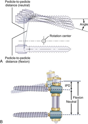
A normal pedicle-to-pedicle excursion during flexion-extension may be 6 to 9 mm, less in lateral bending, and minimal in rotation (Fig. 53–4). The device should permit a normal pedicle-to-pedicle distance excursion to permit normal range of motion and ensure that the device should not act as a “motion stopper” in any direction. Only a few dynamic stabilization devices can accommodate such a large degree of flexibility.
Other Design-Related Factors
Other design-related factors are as follows:
Development of any new device should preferably have an option for an easy salvage in case of failure. Top-loading pedicle screws, accepting regular fusion rods, make implantation simpler and conversion to a fusion more straightforward. Need for in situ tensioning of the device often requires a longer exposure. Posterior devices are inherently kyphogenic, and active lordosis must be built into the design (Fig. 53–5).
Dynamic Stabilization Devices
The classification of dynamic stabilization devices is difficult because new devices are always being introduced, and devices are being constantly withdrawn. As defined earlier, only PDS and IPD devices are included in the classification presented in Table 53–1. The semirigid fixation devices and prosthetic devices, including facet replacement devices, were excluded.
TABLE 53–1 Classification of Posterior Dynamic Stabilization Devices
| Pedicle Screw–Based Posterior Dynamic Stabilization Devices |
The primary goal of dynamic stabilization is treatment of mechanical back pain secondary to spinal instability (Table 53–2). Radicular pain or claudication pain can be adequately treated by decompression alone; the role of additional dynamic stabilization here is only to prevent instability and back pain. Application of a dynamic stabilization device with concomitant decompression to address radicular or claudication leg pain should not be accepted as evidence in support of their efficacy to relieve back pain. Such efficacy can be established only by application of the device to treat mechanical back pain in absence of decompression. When that efficacy is established, application in conjunction with decompression procedures could be justified. Dynamic stabilization to supplement total disc replacement is still at an experimental stage and may be considered as a future indication.
TABLE 53–2 Indications for Posterior Dynamic Stabilization
Clinical Experience with Dynamic Stabilization
Pedicle Screw–Based Posterior Dynamic Stabilization Devices
One of the earliest dynamic stabilization devices is the Graf ligament, described by Graf in 1992.27 This is the first-generation PDS device and forms the basis of many other devices introduced subsequently. It consists of braided polypropylene bands that span between flanges at the titanium pedicle screw heads, placed under tension, locking the facet joints. The surgical procedure is simple, and, in contrast to fusion, it avoids exposure of the transverse processes or the need to harvest bone graft. Clinical outcomes with short-term follow-up (≤2 years) are reported to be as good as with conventional fusions.28 Reports in the literature regarding long-term outcome results with Graf ligament stabilization are conflicting, however. Gardner and Pande29 and Markwalder and Wenger30 reported reasonably good results with Graf ligaments at 5- to 10-year follow-up. Hadlow and colleagues31 performed a retrospective matched case-control comparison between Graf ligamentoplasty and instrumented posterolateral fusion in a consecutive series of 83 patients with low back pain, operated by a single surgeon. The authors concluded that soft stabilization using Graf ligaments produced a worse outcome at 1 year and a significantly higher revision rate at 2 years.
The exact mechanism of action of Graf ligaments has not been established. As a result of the compression applied to the screws, there is a high incidence of radicular symptoms produced secondary to either disc protrusion or foraminal narrowing.28,31 The compressive force may also have a deleterious effect on the facet joint and may lead to back pain. Graf ligaments are still used in a few centers in Europe and Asia, but their use has declined.29,32
The most extensively used dynamic stabilization device is Dynesys (Zimmer Spine, Inc., Warsaw, IN).33,34 The design incorporates a plastic cylinder (sulene-polycarbonate urethane [PCU]) around a cord to apply a distraction force unloading the facet joints, which is thought to be the cause of back pain with Graf ligaments. This is a design improvement over Graf ligaments and may be called a second-generation PDS device. A review of the literature provides the best resource for understanding the mechanism of PDS systems.
In biomechanical testing on cadaveric spines, Dynesys reduced range of flexion more than extension35 (see Fig. 53–2) apparently because the device holds the segment in close to full flexion. Extension is produced by abnormal distraction of the disc space with the plastic cylinder acting as a fulcrum; this is evidenced by abnormal negative disc pressure during extension.36 Conversely, in vivo, Dynesys limits extension more than flexion,37 as expected, because the device acts like an extension stop. This apparent discrepancy results from the fact that in a cadaveric spine only passive stabilizing factors are in operation, and application of a so-called physiologic load to produce spinal motion can never recreate in vivo muscle action, even in a 6-degrees-of-freedom spine tester.36 Studies on disc unloading properties in cadaveric spines, as assessed by measuring the disc pressure, show that in flexion, Dynesys acts as a load-sharing device, which is ideal. In extension, Dynesys becomes totally load bearing, however, allowing no load transmission through the disc (see Fig. 53–3).36
Because of uneven restriction of motion and uneven pattern of unloading the disc, Dynesys may be subjected to excessive stress. This idea is supported by another biomechanical study, which showed high stress at the pedicle screws after Dynesys instrumentation.38 This high stress may explain why screw loosening had been rare with Graf ligament, but fairly common with Dynesys—17% in some clinical series.33,39 The plastic cylinder in Dynesys does not break but may soften with body temperature in vivo and may creep over time, which may lessen the efficacy of the device in distracting the pedicle screws, while protecting it against fatigue failure.
In the initial clinical report, presented by the inventors, Dynesys produced comparable outcome to fusion.34 Greater than 60% of their cases had spinal stenosis, and Dynesys was used in conjunction with decompression; this made it difficult to evaluate whether the good outcome was related to Dynesys or decompression. Subsequent studies by Grob and colleagues33 found that stand-alone Dynesys produced a good outcome in only 39% of cases compared with 69% when combined with decompression. Similar experience was reported by other independent researchers.40
Dynesys has been used in the United States since 2004. Currently, it is approved by the FDA for stabilization of spinal segments as an adjunct to fusion.41 An FDA-controlled investigational device exemption (IDE) clinical trial is in progress comparing Dynesys as a dynamic stabilization device with fusion. The preliminary report shows promising outcome.41 The inclusion criteria include patients with predominant leg pain and exclude patients with predominant back pain. This clinical trial also combines Dynesys with decompression and does not study the effect of Dynesys as a stand-alone device. This study is not expected to establish the clinical efficacy of Dynesys in the treatment of activity-related mechanical back pain, which should be the primary clinical indication for surgical treatment with dynamic stabilization.41
The system comes preassembled or can be assembled on the back table and does not require in situ tensioning. It is implanted between regular, top-loading pedicle screws, making insertion and conversion to fusion as a salvage procedure simpler. It incorporates a soft bumper at the end, which allows adequate pedicle-to-pedicle excursion in flexion-extension. The length of the spacer defines the amount of unloading of the facet joints. The capability of creating an active lordosis is built into the metal spools that connect the soft section of the device to the pedicle screws. Lordosis ensures unloading of the disc (see Fig. 53–4B). These two important mechanical properties permit uniform motion restriction in all directions and uniform load sharing throughout the range of motion, which is important to increase resistance to fatigue. Although the Transition Stabilization System has several design improvements compared with Dynesys, its advantages remain to be established. The device has been approved by the FDA only more recently under 510K as a fusion device, but to date no clinical outcomes have been reported.
The DSS-II Dynamic Stabilization System (Abbott Spine, Inc., Austin, TX)42 was developed by the author and is one of the earliest titanium metallic springs used for dynamic stabilization. Its predecessor, the DSS-I, was a C-shaped titanium spring that, on biomechanical testing, showed uneven restriction to extension and excessive unloading of the disc in extension, indicating the possibility of fatigue failure. It was never used clinically. The second-generation DSS-II is an A-shaped titanium spring implanted between the pedicle screws. This design improvement produces active lordosis and permits adequate pedicle-to-pedicle excursion and physiologic translation of the instant axis of rotation of the motion segment. The system allows uniform motion restriction and uniform load sharing throughout the range of motion, the two essential biomechanical characteristics for survival of the implant against fatigue failure. The device has never been introduced for general use, but a pilot clinical trial was completed in Sao Paulo, Brazil, in a small group of patients (n = 19) with mechanical back pain without need for decompression. The clinical outcome was encouraging, but more importantly, no implant failure was observed in 2 to 3 years of follow-up.42
The BioFlex (BioSpine Corporation, Seoul, Korea)43 is a coil spring made of 4-mm diameter nitinol for increased flexibility; it has been used extensively in Seoul, Korea. This device has been used most commonly in conjunction with interbody cages to achieve fusion, although it has also been used alone as a nonfusion device.44 A titanium version of the device has been approved more recently by the FDA under 510K as a fusion device, but no clinical use in the United States has been reported yet.
Stabilimax NZ (Applied Spine Technologies, Inc., New Haven, CT),45 a dual core spring device developed by Panjabi, is designed to apply soft resistance against compression and distraction. The design rationale is to limit the neutral zone motion, while leaving the elastic zone unaffected. At the present time, the device is undergoing an FDA-controlled IDE trial to assess whether it is at least as safe and effective as fusion in patients receiving decompression surgery for the treatment of clinically symptomatic spinal stenosis at one or two contiguous vertebral levels from L1-S1.46
The Cosmic Posterior Dynamic System (Ulrich GmbH & Co, Ulm, Germany)47 has a unique design that incorporates a rigid rod connected to pedicle screws with a hinged screw-head that is expected to permit motion. No biomechanical data are available in the peer-reviewed literature. There are some clinical reports of its use in non–peer-reviewed journals.48
Hybrid devices incorporate a metallic rod connected to a flexible segment, with a nonmetallic bumper to allow shock absorption and some degree of pedicle-to-pedicle excursion. The obvious clinical advantage is that these devices look like a fusion rod and can be used with a regular top-loading pedicle screw. The CD Horizon Agile system (Medtronic Sofamor Danek, Memphis, TN) incorporates a soft cylindric bumper at the end of a fusion rod, held by a metallic cable in its center, similar to the fabric cord used in the Dynesys system described earlier. After initial clinical use, the device was recalled by the company for reported fatigue failure of the cable. NFlex (N Spine, Inc., San Diego, CA) has a similar design, in which a 6-mm titanium fusion rod is connected to a flexible end, made of a 3.25-mm titanium core and PCU sleeve. The sleeve allows soft resistance to flexion and extension, permitting the essential pedicle-to-pedicle excursion. Although the device may permit compression and elongation, its ability to permit anteroposterior translation remains a concern. The device has been used clinically since fall 2006, but no clinical experience has been published.50
Interspinous Distraction Devices
The most frequently used interspinous distraction device at the present time is the X-Stop IPD device (Medtronic, Memphis, TN). This titanium spacer can be inserted with a minimally invasive approach under local anesthesia; elderly patients with medical comorbidities are considered good candidates. Biomechanical studies in cadaveric spines have shown that the X-Stop significantly decreases posterior intradiscal pressure,51,52 reduces facet pressures, and decreases contact area at the facets.53 An in vivo study with MRI also showed that the X-Stop device increases the spinal canal and foramen diameter during extension.54 This device holds the spine in a position of flexion, a position of relief from claudication pain. Because it is not tied to the adjacent spinous processes, it can permit further flexion.
In a prospective, randomized, multicenter study on 191 patients with neurogenic intermittent claudication, the efficacy of the X-Stop was compared with nonoperative treatment.55 At 2 years of follow-up, the X-Stop group had improved symptom severity, physical function, and patient satisfaction scores at all of the time points compared with the nonoperative group. The reoperation rate was 6% at 2 years for the X-Stop group, which is comparable to the reoperation rate for lumbar decompression procedures. There were some limitations to this study, including a lack of blinding and loss to follow-up. The major limitation of the study was failure to compare the efficacy of X-Stop with a conventional surgical treatment for spinal stenosis (i.e., decompressive laminectomy). The device received FDA approval for use in one-level or two-level stenosis in patients older than 50 years with significant neurogenic claudication with or without back pain, after failed conservative treatment for at least 6 months. The main complication of this device is dislodgment of the spacer with or without breakage of spinous processes.
The Wallis device (Zimmer Spine, Inc., Minneapolis, MN) is a polyetheretherketone (PEEK) spacer, retained between the spinous processes by a Dacron tape, which prevents its accidental dislodgment.56 This device holds the spine in flexion and limits extension. The holding ligaments also restrict further flexion. As a result, the manufacturer and inventors have recommended its use for indications beyond spinal stenosis (e.g., mechanical back pain with early disc degeneration).57,58 An FDA IDE trial is currently comparing the Wallis system with total disc replacement for the treatment of mild to moderate degenerative disc disease of the lumbar spine at the L4-5 level.59
Coflex (Paradigm Spine, LLC, New York, NY) is a U-shaped titanium device, retained in place by clamping its wings around the adjacent spinous processes. In contrast to other IPD devices, it allows flexion and extension, and it does not act as an extension stop. Biomechanical studies report that it restores normal flexion-extension in a destabilized spine rather than holding the spine in flexion.60 Kong and colleagues61 reported a comparable outcome at 1-year follow-up with Coflex and posterior lumbar interbody fusion for degenerative back pain. The Coflex group had preserved motion, however, whereas the posterior lumbar interbody fusion group had an adverse effect on the adjacent segment. At the time of writing this chapter, one FDA-approved IDE trial with Coflex was in progress comparing the Coflex device with instrumented fusions.
DIAM (Medtronic Sofamor Danek, Memphis, TN) is an H-shaped, polyester-covered, silicone bumper that is placed between the spinous processes with a suture to hold it in place. The device has been used in Europe for a few years. A more recent clinical study failed to establish efficacy of DIAM in improving back pain compared with decompression alone.62 An FDA-regulated clinical trial for DIAM was initiated in late 2006 for patients with lumbar spinal stenosis. The FDA also granted another IDE trial to study DIAM in patients with low back pain caused by degenerative disc disease.
The PercuDyn system (Interventional Spine, Inc., Irvine CA) is not an IPD device, but it is described as a minimally invasive facet augmentation device, which prevents extension by stopping the overriding of the facet joints. It consists of a 10-mm diameter PCU bumper over a cannulated 4.5-mm titanium screw, which can be inserted percutaneously into the pedicle, sitting below the inferior facet. The bumper acts as an extension-limiting soft cushion. The clinical experience with this device is limited.63
Summary
Pearls
Pitfalls
Key Points
1 Mulholland RC, Sengupta DK. Rationale, principles and experimental evaluation of the concept of soft stabilization. Eur Spine J. 2002;11(Suppl 2):S198-S205.
2 Panjabi MM. Clinical spinal instability and low back pain. J Electromyogr Kinesiol. 2003;13:371-379.
3 Bono CM, Kadaba M, Vaccaro AR. Posterior pedicle fixation-based dynamic stabilization devices for the treatment of degenerative diseases of the lumbar spine. J Spinal Disord Tech. 2009;22:376-383.
4 Stoll TM, Dubois G, Schwarzenbach O. The dynamic neutralization system for the spine: A multi-center study of a novel non-fusion system. Eur Spine J. 2002;11(Suppl 2):S170-S178.
This was the first report of clinical outcome of the Dynesys PDS system from its inventor Dubois.
5 Zucherman JF, Hsu KY, Hartjen CA, et al. A multicenter, prospective, randomized trial evaluating the X STOP interspinous process decompression system for the treatment of neurogenic intermittent claudication: Two-year follow-up results. Spine (Phila Pa 1976). 2005;30:1351-1358.
1 Bono CM, Kadaba M, Vaccaro AR. Posterior pedicle fixation-based dynamic stabilization devices for the treatment of degenerative diseases of the lumbar spine. J Spinal Disord Tech. 2009;22:376-383.
2 Bono CM, Lee CK. Critical analysis of trends in fusion for degenerative disc disease over the past 20 years: Influence of technique on fusion rate and clinical outcome. Spine (Phila Pa 1976). 2004;29:455-463.
3 Gibson JN, Waddell G: Surgery for degenerative lumbar spondylosis. Cochrane Database Syst Rev (2):CD001352, 2005.
4 Cheh G, Bridwell KH, Lenke LG, et al. Adjacent segment disease following lumbar/thoracolumbar fusion with pedicle screw instrumentation: A minimum 5-year follow-up. Spine (Phila Pa 1976). 2007;32:2253-2257.
5 Panjabi MM. Hybrid multidirectional test method to evaluate spinal adjacent-level effects. Clin Biomech (Bristol, Avon). 2007;22:257-265.
6 Dvorak J, Panjabi MM, Chang DG, et al. Functional radiographic diagnosis of the lumbar spine: Flexion-extension and lateral bending. Spine (Phila Pa 1976). 1991;16:562-571.
7 Sengupta DK, Herkowitz HN. Degenerative spondylolisthesis: Review of current trends and controversies. Spine (Phila Pa 1976). 2005;30(6 Suppl):S71-S81.
8 Pope MH, Panjabi M. Biomechanical definitions of spinal instability. Spine (Phila Pa 1976). 1985;10:255-256.
9 Okawa A, Shinomiya K, Komori H, et al. Dynamic motion study of the whole lumbar spine by videofluoroscopy. Spine (Phila Pa 1976). 1998;23:1743-1749.
10 Murata M, Morio Y, Kuranobu K. Lumbar disc degeneration and segmental instability: A comparison of magnetic resonance images and plain radiographs of patients with low back pain. Arch Orthop Trauma Surg. 1994;113:297-301.
11 Paajanen H, Tertti M. Association of incipient disc degeneration and instability in spondylolisthesis: A magnetic resonance and flexion-extension radiographic study of 20-year-old low back pain patients. Arch Orthop Trauma Surg. 1991;111:16-19.
12 Fujiwara A, Tamai K, An HS, et al. The relationship between disc degeneration, facet joint osteoarthritis, and stability of the degenerative lumbar spine. J Spinal Disord. 2000;13:444-450.
13 Mulholland RC, Sengupta DK. Rationale, principles and experimental evaluation of the concept of soft stabilization. Eur Spine J. 2002;11(Suppl 2):S198-S205.
14 Frymoyer JW, Krag MH. Spinal stability and instability: Definitions, classification, and general principles of management. In: Dunsker SB, Schmidek HH, Frymoyer J, Kahn A, editors. The Unstable Spine. New York: Grune & Stratton, 1986.
15 Jackson JP, Waugh W, Green JP. High tibial osteotomy for osteoarthritis of the knee. J Bone Joint Surg Br. 1969;51:88-94.
16 Moore RJ, Vernon-Roberts B, Fraser RD, et al. The origin and fate of herniated lumbar intervertebral disc tissue. Spine (Phila Pa 1976). 1996;21:2149-2155.
17 McNally DS. The objectives for the mechanical evaluation of spinal instrumentation have changed. Eur Spine J. 2002;11(Suppl 2):S179-S185.
18 Keller TS, Hansson TH, Abrams AC, et al. Regional variations in the compressive properties of lumbar vertebral trabeculae: Effects of disc degeneration. Spine (Phila Pa 1976). 1989;14:1012-1019.
19 Simpson EK, Parkinson IH, Manthey B, et al. Intervertebral disc disorganization is related to trabecular bone architecture in the lumbar spine. J Bone Miner Res. 2001;16:681-687.
20 McNally DS, Shackleford IM, Goodship AE, et al. In vivo stress measurement can predict pain on discography. Spine (Phila Pa 1976). 1996;21:2580-2587.
21 McNally DS, Adams MA. Internal intervertebral disc mechanics as revealed by stress profilometry. Spine (Phila Pa 1976). 1992;17:66-73.
22 Nockels RP. Dynamic stabilization in the surgical management of painful lumbar spinal disorders. Spine (Phila Pa 1976). 2005;30(16 Suppl):S68-S72.
23 Panjabi MM. Clinical spinal instability and low back pain. J Electromyogr Kinesiol. 2003;13:371-379.
24 Fujiwara A, Lim TH, An HS, et al. The effect of disc degeneration and facet joint osteoarthritis on the segmental flexibility of the lumbar spine. Spine (Phila Pa 1976). 2000;25:3036-3044.
25 Lidar Z, Beaumont A, Lifshutz J, et al. Clinical and radiological relationship between posterior lumbar interbody fusion and posterolateral lumbar fusion. Surg Neurol. 2005;64:303-308. discussion 308
26 Pfeiffer M, Hildebrand R, Grande ME, et al. Evaluation of indication-based use of transpedicular instrumentations with different rigidity for lumbar spinal fusion: A prospective pilot study with 3 years of follow-up. Eur Spine J. 2003;12:369-377.
27 Graf H. Lumbar instability: Surgical treatment without fusion. Rachis. 1992;412:123-137.
28 Grevitt MP, Gardner AD, Spilsbury J, et al. The Graf stabilisation system: Early results in 50 patients. Eur Spine J. 1995;4:169-175. discussion 175
29 Gardner A, Pande KC. Graf ligamentoplasty: A 7-year follow-up. Eur Spine J. 2002;11(Suppl 2):S157-S163.
30 Markwalder TM, Wenger M. Dynamic stabilization of lumbar motion segments by use of Graf’s ligaments: Results with an average follow-up of 7.4 years in 39 highly selected, consecutive patients. Acta Neurochir (Wien). 2003;145:209-214. discussion 214
31 Hadlow SV, Fagan AB, Hillier TM, et al. The Graf ligamentoplasty procedure: Comparison with posterolateral fusion in the management of low back pain. Spine (Phila Pa 1976). 1998;23:1172-1179.
32 Kanayama M, Hashimoto T, Shigenobu K, et al. A minimum 10-year follow-up of posterior dynamic stabilization using Graf artificial ligament. Spine (Phila Pa 1976). 2007;32:1992-1996. discussion 1997
33 Grob D, Benini A, Junge A, et al. Clinical experience with the Dynesys semirigid fixation system for the lumbar spine: surgical and patient-oriented outcome in 50 cases after an average of 2 years. Spine (Phila Pa 1976). 2005;30:324-331.
34 Stoll TM, Dubois G, Schwarzenbach O. The dynamic neutralization system for the spine: A multi-center study of a novel non-fusion system. Eur Spine J. 2002;11(Suppl 2):S170-S178.
35 Schmoelz W, Huber JF, Nydegger T, et al. Dynamic stabilization of the lumbar spine and its effects on adjacent segments: An in vitro experiment. J Spinal Disord Tech. 2003;16:418-423.
36 Schmoelz W, Huber JF, Nydegger T, et al. Influence of a dynamic stabilisation system on load bearing of a bridged disc: An in vitro study of intradiscal pressure. Eur Spine J. 2006;15:1276-1285.
37 Beastall J, Karadimas E, Siddiqui M, et al. The Dynesys lumbar spinal stabilization system: A preliminary report on positional magnetic resonance imaging findings. Spine (Phila Pa 1976). 2007;32:685-690.
38 Meyers K, Tauber B, Sudin Y, et al. Use of instrumented pedicle screws to evaluate load sharing in posterior dynamic stabilization systems. Spine J. 2008;8:926-932.
39 Sapkas GS, Themistocleous GS, Mavrogenis AF, et al. Stabilization of the lumbar spine using the dynamic neutralization system. Orthopedics. 2007;30:859-865.
40 Wurgler-Hauri CC, Kalbarczyk A, Wiesli M, et al. Dynamic neutralization of the lumbar spine after microsurgical decompression in acquired lumbar spinal stenosis and segmental instability. Spine (Phila Pa 1976). 2008;33:E66-E72.
41 Welch WC, Cheng BC, Awad TE, et al. Clinical outcomes of the Dynesys dynamic neutralization system: 1-year preliminary results. Neurosurg Focus. 2007;22:E8.
42 Sengupta DK. Dynamic stabilization system. In: Yue JJ, McAfee PC, An HS, editors. Motion Preservation Surgery of the Spine—Advanced Techniques and Controversies. Philadelphia: Saunders; 2008:472-475.
43 Kim YS, Moon BJ. Bioflex spring rod pedicle screw system. In: Kim DH, Fessler RG, editors. Dynamic Reconstruction of the Spine. New York: Thieme; 2006:340-346.
44 Kim YS, Zhang HY, Moon BJ, et al. Nitinol spring rod dynamic stabilization system and nitinol memory loops in surgical treatment for lumbar disc disorders: Short-term follow up. Neurosurg Focus. 2007;22:E10.
45 Yue JJ, Timm JP, Panjabi MM, et al. Clinical application of the Panjabi neutral zone hypothesis: The Stabilimax NZ posterior lumbar dynamic stabilization system. Neurosurg Focus. 2007;22:E12.
46 Yue JJ, Malcolmon G, Timm JP. The Stabilimax NZ posterior lumbar dynamic stabilization system. In: Yue JJ, McAfee PC, An HS, editors. Motion Preservation Surgery of the Spine—Advanced Techniques and Controversies. Philadelphia: Saunders; 2008:476-482.
47 Karabekir HS, Sedat C, Mehmet Z. Clinical outcomes of cosmic dynamic neutralization system: Preliminary results of 1-year. J Minim Invas Spinal Technol. 2(3), 2008.
48 von Strempel A, et al. Stabilisation of the degenerated lumbar spine in the nonfusion technique with cosmic posterior dynamic system. World Spine J. 2006;1:40-47.
49 Mandigo CE, Sampath P, Kaiser MG. Posterior dynamic stabilization of the lumbar spine: Pedicle based stabilization with the AccuFlex rod system. Neurosurg Focus. 2007;22:E9.
50 Wallach CJ, Teng AL, Wang JC. NFlex. In: Yue JJ, McAfee PC, An HS, editors. Motion Preservation Surgery of the Spine—Advanced Techniques and Controversies. Philadelphia: Saunders; 2008:505-510.
51 Lindsey DP, Swanson KE, Fuchs P, et al. The effects of an interspinous implant on the kinematics of the instrumented and adjacent levels in the lumbar spine. Spine (Phila Pa 1976). 2003;28:2192-2197.
52 Swanson KE, Lindsey DP, Hsu KY, et al. The effects of an interspinous implant on intervertebral disc pressures. Spine (Phila Pa 1976). 2003;28:26-32.
53 Wiseman CM, Lindsey DP, Fredrick AD, et al. The effect of an interspinous process implant on facet loading during extension. Spine (Phila Pa 1976). 2005;30:903-907.
54 Richards JC, Majumdar S, Lindsey DP, et al. The treatment mechanism of an interspinous process implant for lumbar neurogenic intermittent claudication. Spine (Phila Pa 1976). 2005;30:744-749.
55 Zucherman JF, Hsu KY, Hartjen CA, et al. A multicenter, prospective, randomized trial evaluating the X STOP interspinous process decompression system for the treatment of neurogenic intermittent claudication: Two-year follow-up results. Spine (Phila Pa 1976). 2005;30:1351-1358.
56 Senegas J. Mechanical supplementation by non-rigid fixation in degenerative intervertebral lumbar segments: The Wallis system. Eur Spine J. 2002;11(Suppl 2):S164-S169.
57 Floman Y, Millgram MA, Smorgick Y, et al. Failure of the Wallis interspinous implant to lower the incidence of recurrent lumbar disc herniations in patients undergoing primary disc excision. J Spinal Disord Tech. 2007;20:337-341.
58 Senegas J, Vital JM, Pointillart V, et al. Long-term actuarial survivorship analysis of an interspinous stabilization system. Eur Spine J. 2007;16:1279-1287.
59 Christie SD, Song JK, Fessler RG. Dynamic interspinous process technology. Spine (Phila Pa 1976). 2005;30(16 Suppl):S73-S78.
60 Tsai KJ, Murakami H, Lowery G, et al. A biomechanical evaluation of an interspinous device (Coflex) used to stabilize the lumbar spine. J Surg Orthop Adv. 2006;15:167-172.
61 Kong DS, Kim ES, Eoh W. One-year outcome evaluation after interspinous implantation for degenerative spinal stenosis with segmental instability. J Korean Med Sci. 2007;22:330-335.
62 Kim KA, McDonald M, Pik JH, et al. Dynamic intraspinous spacer technology for posterior stabilization: Case-control study on the safety, sagittal angulation, and pain outcome at 1-year follow-up evaluation. Neurosurg Focus. 2007;22:E7.
63 Palmer S, Mahar A, Oka R. Biomechanical and radiographic analysis of a novel, minimally invasive, extension-limiting device for the lumbar spine. Neurosurg Focus. 2007;22:E4.