Chapter 7 Physics of radiography
 In order to standardise the units of measurement used in science, the International System of Units (SI) was developed, which is derived from seven standard base units.


 Electromagnetic radiation is a spectrum of energy levels containing a wide range of radiation types.
INTRODUCTION
It is essential that any practitioner operating within the realms of an imaging department and using ionising radiation has a sound knowledge base. In order to comprehend the various factors affecting the production of diagnostic images, there is a requirement to demonstrate an awareness of the fundamental definitions of classical physics and how these terms may be applied to radiography. An understanding of atomic structure, the electromagnetic spectrum, electricity, magnetism and the inverse square law are also essential principles that can be applied to radiography.
DERIVED SI UNITS RELEVANT TO RADIOGRAPHIC PRACTICE
Derived SI units result from a combination of the base units and some of them are used frequently in radiography. Practitioners are required to name them and define their values (Table 7.1). Some of these derived SI units are outlined below.
| Term and SI unit | Definition | Application to radiography |
|---|---|---|
| Energy (joule; J) | The ability to do work | Production of X-rays |
| Mass (kilogram; kg) | A measure of the number of atoms and molecules in a body | Important when determining the radiation dose to a patient |
| Gray (joules per kilogram; Gy) | The energy imparted to a body by ionising radiation | Unit of absorbed radiation dose measurement |
| Sievert (joules per kilogram, Sv) | The energy imparted to a body by ionising radiation multiplied by the quality factor | Unit of radiation dose equivalent, which takes biological factors into account |
| Power (joules per second) | The rate of doing work | Output of X-ray generator |
| Electric current (ampere; A) | The movement of electrons flowing per unit time | Quantity of electrons flowing per unit time |
| Electric charge (coulomb; C) | 1 ampere flowing per second | Quantity of electrons flowing per second |
| Electrical potential (volt; V) | The force which moves electrons within a conductive material | Potential difference across an X-ray tube, acceleration of electrons and quality of X-ray beam |
| Frequency (hertz; Hz) | The number of cycles per second | Electromagnetic radiation |
ENERGY
This may be a difficult concept to understand but fundamentally energy is the ability to do work. This may be demonstrated in radiography as potentialenergy (PE), which is applied to the negative (cathode) and positive (anode) ends of an X-ray tube, subsequently causing the flow of electrons across the vacuum environment. This is kinetic energy (KE) and is subsequently converted into X-ray energy (photons) when the electrons interact with the anode material (tungsten atoms).
ATOMIC STRUCTURE
All matter consists of atoms and can be thought of as having a central nucleus surrounded by a cloud of particles called electrons (Fig. 7.1). The diameter of the nucleus is approximately 10−15 m.
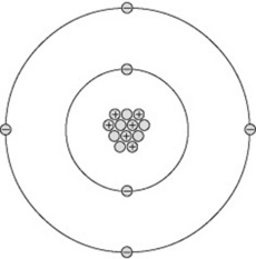
The nucleus contains a number of particles called protons and neutrons, together termed nucleons. Each nucleon is nearly 2000 times the mass of an electron. This means the mass of an atom is concentrated in its nucleus, around which the much lighter electrons orbit. If a nucleus were scaled up to the centre spot of a football pitch, the electrons would start orbiting around the perimeter of the pitch in their various orbits stretching out for several miles. This analogy demonstrates why X-rays may pass through a body of material unattenuated, as the X-ray photons may simply pass ‘between’ the electron orbits and totally miss the nucleus of an atom.
ELECTRONS
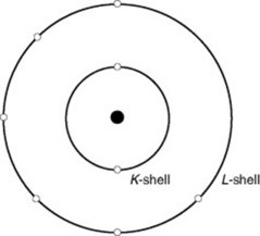
Electrons are the small, light particles orbiting the nucleus of an atom. They are arranged in shells, called K, L, M, N, O and P. Normally, the number of electrons orbiting the nucleus equals the number of protons in the nucleus. An atom of oxygen, for example, has 8 electrons orbiting the central nucleus in the K shell (n = 2) and L shell (n = 6) (Fig. 7.2).
An element is the simplest form in which matter exists. Examples include oxygen, nitrogen and tungsten. Each element only contains atoms of each particular chemical; in other words, the element oxygen only contains the specific atoms for this chemical. Most elements are unable to exist in a single form so they combine with other elements and become compounds. Examples of compounds include water, which comprises two atoms of hydrogen combined with one atom of oxygen. This is chemically expressed as H2O.
CHEMICAL SYMBOLS
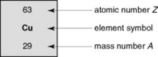
An element can be represented by its chemical symbol (Fig. 7.3) with its proton number as a subscript and its nucleon number as a superscript to the left hand side of the symbol. An element identified in this way is known as a nuclide. Expressing the nuclide in this way gives the practitioner all the information required to illustrate the number of protons and neutrons (nucleons in the nucleus) and the number of orbiting electrons. For example, carbon-14, which has a proton number of 6 but a nucleon number of 14 (i.e. it has 8 neutrons) can be represented as 14C. The proton number could appear as a subscript, but as carbon, by definition, has six protons, that is not strictly needed.
ELECTROMAGNETIC RADIATION
The electromagnetic radiation (EMR) spectrum encompasses a wide range of radiation types, such as X-rays, gamma rays, light, microwaves and radio waves. Figure 7.4 depicts the EMR spectrum and, as the term suggests, EMR consists of both electric and magnetic fields. These fields are at right angles to each other and travel through a vacuum at the same velocity as light (3 × 10⁸ m s−1). Outside a vacuum environment,EMR interacts with matter, which may absorb part of this energy and affect it.
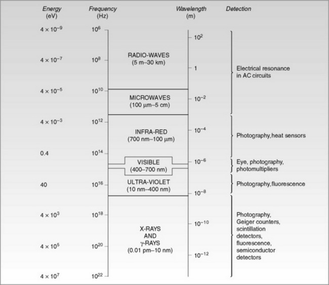
As illustrated in Figure 7.4, the EMR has a range of frequencies and wavelengths. All EMR exhibit the same set of properties. EMR may be illustrated by plotting the energy against distance, giving a sine wave.
In terms of diagnostic imaging, all aspects of the EMR spectrum are relevant to some area of clinical practice (Table 7.2).
Table 7.2 Aspects of electromagnetic radiation (EMR) within the clinical imaging department
| Aspect of EMR | Clinical use |
|---|---|
| X-rays | Obtaining diagnostic images |
| Gamma rays | Nuclear medicine |
| Ultra-violet light | Conventional film–screen combinations |
| Visible light | Viewing radiographs |
| Radio waves | Radiofrequency pulses in MRI |
| Infra-red light | Heat transfer from the anode of a rotating anode X-ray tube |
MAGNETISM
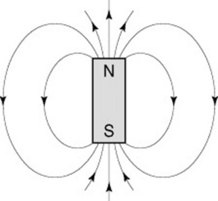
Practitioners must also be aware that there are forces which exist between magnets. ‘Like’ poles repel each other and ‘unlike’ poles attract. Thus, if a north pole of a magnet approaches another north pole they will repel each other and you will be unable to get the magnets to touch. However, if one magnet is rotated they will become firmly attached at the poles. It is normal practice in physics to consider the north pole as positive and the south pole as negative. A magnet also exhibits magnetic fields, which exert a force around it, and this can be demonstrated by using iron filings, which adhere to the lines of force (Fig. 7.5).
ELECTROMAGNETISM
Magnetism is associated with the alignment and movement of electrons and therefore the atom. As all atoms have moving electrons around their nucleus there are always weak magnetic forces associated with atoms. Therefore, when a current passes through a wire there are millions of electrons moving along the wire and it is this process which cause the wire to become magnetised. The wire also exhibits a magnetic field around it and this effect is known as electromagnetism. Single strands of wire exhibit a magnetic effect; however, to enable us to use the phenomenon effectively we need to coil the wire to make a solenoid. If a soft iron bar is place within the solenoid this increases the magnetic flux considerably because of the induced magnetism within the iron. The combination of a solenoid with an iron core is known as an electromagnet.Electromagnets are used in equipment as locks for the X-ray tube mounting.
ELECTRICITY
ELECTRIC CURRENT
This is a considerable number of electrons and amounts to 6 × 10¹⁸ electrons per second. The potential difference across the circuit is measured in kilovolts and determines the rate at which the electrons move. High potential differences are used in the X-ray circuit and vary between 40 and 150 kVp (see p. 108).
RESISTANCE
Resistance is the force which tries to impede the flow of electrons. It is measured in ohms (Ω) and the resistance in any material depends upon its shape, the type of substance and the temperature of the material. Metals have low resistance to the passage of electrons whereas insulators have muchhigher values of resistance. The optimum shape of a conductor to reduce the resistance is one of large cross-sectional area and, of course, the longer the conductor the greater the resistance.
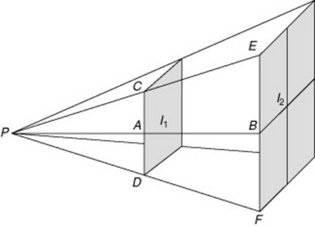
INVERSE SQUARE LAW

The intensity of the X-ray beam decreases with an increase in distance. This happens due to the diverging nature of the X-ray beam rather than to the interaction of X-ray photons with matter. The energy of the X-ray beam is spread over an increasing area as the distance from the source increases. By doubling the distance, the intensity is reduced to a quarter of its original value. This is demonstrated in the Figure 7.6, where the result of increasing the distance from d1 to d2 results in a reduction of the intensity of the X-ray beam to a quarter of that of d1.
THE INVERSE SQUARE LAW IN PRACTICE
Example of inverse square law
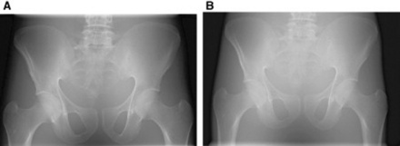
Question: The reading from a dose area product (DAP) meter was 1041 mGy cm2 (see Table 7.1 for SI units) for a phantom pelvis examination performed at 100 cm SID. What is the approximate DAP meter reading for the same examination (using the exact same exposure factors) at 200 cm SID?
Answer: Substituting into the equation given above, we can see that 1/d2 increases from 1/1002 to 1/2002 when the distance doubles. So if I ∝1/10 000 and has a value of 1041 mGy cm2, then I ∝1/40 000 must have a value of 1041 × ¼, which means the absorbed DAP is reduced to approximately 260 mGy × cm2. The resultant image would, however, appear with less contrast and not as dense in comparison to the image taken at 100 cm, as only the higher energy portion of the X-ray beam would reach the image receptor. The lower energy X-ray photons would either be absorbed or scatter, potentially failing to reach the image receptor. This is demonstrated in the images in Figure 7.7.
Ball J, Moore AD. Essential physics for radiographers, 3rd edn. London: Blackwell, 1997.
A clear and straightforward introduction to physics for radiographers..
Farr RF, Allisy-Roberts PJ. Physics for medical imaging. London: Saunders, 1997.
Graham DT, Cloke P. Principles of radiological physics, 4th edn. London: Churchill Livingstone, 2003.