Photostimulable Phosphor Image Capture
Objectives
On completion of this chapter, you should be able to:
• Describe the basic construction of a photostimulable phosphor (PSP) cassette and imaging plate.
• Describe the purpose of each layer of the imaging plate.
• Explain the process of photostimulation in the imaging plate.
• Explain the process of reading and erasing the imaging plate.
• Compare conventional radiographic screen and film speed to PSP systems.
• Discuss the importance of matching the body part being examined to the examination menu.
• Discuss the selection of technical factors for density, contrast, and penetration.
• Describe the imaging plate and grid selection process.
• Discuss the importance of preprocessing collimation and image marking.
• Compare exposure indicators for the major computed radiography manufacturers and vendors.
Key Terms
Artifacts
Backing layer
Barcode label
Bit depth
Cassette
Color layer
Collimation
Conductive layer
Fast scan direction
Focused grid
Grid frequency
Grid ratio
Imaging plate
Kilovoltage peak (kVp)
Laser
Milliamperage seconds (mAs)
Moiré
Phosphor center
Phosphor layer
Photodetector
Photostimulable phosphor
Protective layer
Reflective layer
Quantum mottle
Quantum noise
Shuttering
Slow scan direction
Support layer
The phrase digital radiographic image acquisition and processing is used in this book to categorize the different ways of acquiring and processing digital radiographic images. One way to do this is through photostimulable phosphor (PSP) systems. These systems can be either cassette-based or cassette-less in design. This chapter introduces the process of acquiring an image using PSP technology. Key topics include technical factors, equipment selection, exposure indicators, image data recognition, and artifacts.
The term radiographic refers to general x-ray procedures as distinct from other digital modalities such as computed tomography (CT), magnetic resonance imaging (MRI), and ultrasound (US).
This chapter introduces the basic principles of PSP and discusses how PSP equipment works. Some similarities between PSP and conventional radiography are discussed. A basic understanding of how PSP works prepares the technologist to make sound ethical decisions when performing radiographic examinations.
Cassette-based PSP systems differ from conventional radiography in that the cassette is simply a lightproof container that protects an imaging plate from light and handling. The imaging plate takes the place of radiographic film and is capable of storing an image formed by incident x-ray photon excitation of phosphors. The cassette-less systems using PSP technology function in a similar fashion but without the need of a cassette. During the reading process, the phosphor releases the stored light and converts it into an electrical signal, which is then digitized.
PSP Equipment
Cassette
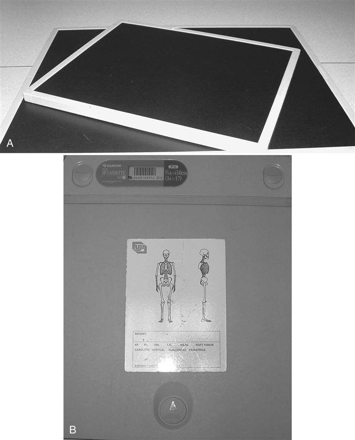
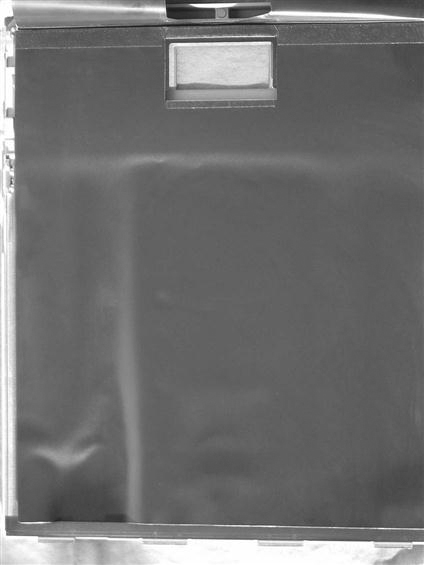
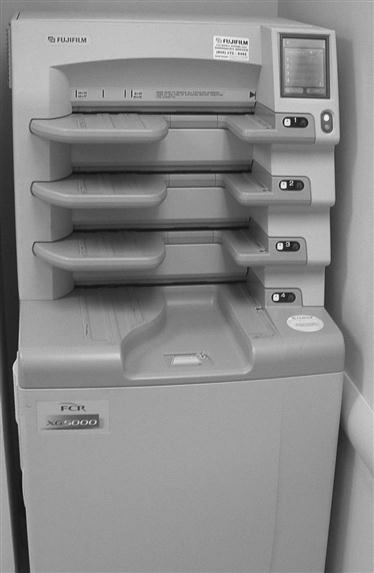
The PSP cassette looks like the conventional screen-film cassette. It consists of a durable, lightweight plastic material (Figure 4-1). The cassette is backed by a thin sheet of aluminum or lead that absorbs backscatter x-ray photons (Figure 4-2). In addition to holding the PSP plate, the cassette contains an antistatic material (usually felt) that protects against static electricity buildup, dust collection, and mechanical damage to the plate (Figure 4-3).
Imaging Plate
Construction.
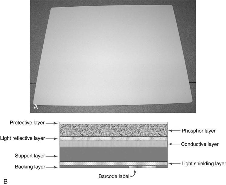
In PSP systems, the radiographic image is recorded on a thin sheet of plastic known as the imaging plate. The imaging plate consists of several layers (Figure 4-4):
• A protective layer. This is a very thin, tough, clear plastic that protects the phosphor layer.
• A conductive layer. This is a layer of material that absorbs and reduces static electricity.
• A support layer. This is a semi-rigid material that gives the imaging sheet some strength.
• A backing layer. This is a soft polymer that protects the back of the cassette.
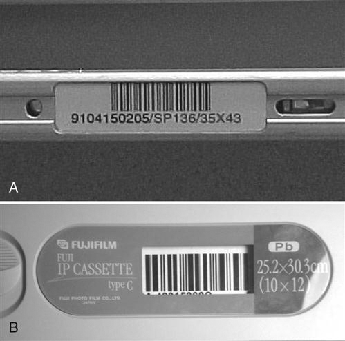
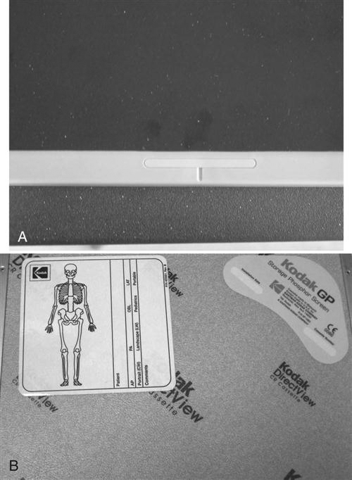
Cassette-based PSP systems contain a window with a barcode label or barcode sticker on the cassette that allows the technologist to match the image information with the patient-identifying barcode on the examination request (Figure 4-5). For each new examination, the patient-identifying barcode and the barcode label on the cassette must be scanned and connected to the patient position or examination menu. In cassette-less systems, the image must be matched with the examination worklist on the computer and there will not be a paper-type sticker for the plate. The cassette-based system may also have a label such as a colored mark or sticker where applicable to indicate the appropriate orientation of the cassette in relation to the patient (Figure 4-6). When the cassette is oriented correctly, less image manipulation is required after processing. When the examination type is associated with the cassette, an automatic screen orientation of the image is built within the software. If the cassette was correctly oriented, the image will be displayed correctly; if not, the image will need to be rotated or flipped on the screen to display the image in correct anatomic orientation.
Acquiring and Forming the Image.
With PSP systems, the patient is x-rayed exactly the same way as in conventional radiography. The patient is positioned using appropriate positioning techniques, and the body part is aligned with the image receptor. The patient is then exposed using the proper combination of kilovoltage peak (kVp), milliamperage seconds (mAs), and distance. The difference lies in how the exposure is recorded. In PSP, the remnant beam interacts with electrons in the barium fluorohalide crystals contained within the imaging plate. This interaction stimulates, or gives energy to, electrons in the crystals, trapping them in an area of the crystal known as the color or phosphor center. This trapped signal will remain for hours, even days, although deterioration begins almost immediately. In fact, the trapped signal is never completely lost. That is, a certain amount of an exposure remains trapped so that the imaging plate can never be completely erased. However, the residual trapped electrons are so few in number that they do not interfere with subsequent exposures.
The Reader
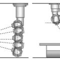
There are two types of PSP readers: point scan and line scan. Point scan readers have an optical stage, a scanning laser beam, translation mechanics, a light pickup guide, a photomultiplier, a signal transformer/amplifier, and an analog-to-digital converter (ADC). At any point in time, only a single laser point radiates the imaging plate. Line scan readers are based on simultaneous stimulation of the imaging plate one line at a time, and with line scan readers, the acquisition of the photostimulated luminescence (PSL) occurs with a charge-coupled device (CCD) linear array photodetector. PSL refers to the emission of light from the phosphor layer after stimulation by the relevant light source. Instead of a single laser beam, there is a scanning module that contains several linear laser units and optical light collection lenses. The line scan system requires a lens array to focus each laser beam to a corresponding point on the CCD array.
With PSP systems, no chemical processor or darkroom is necessary. Instead, following exposure, the cassette is fed into a reader (Figure 4-7) that removes the imaging plate and scans it with a laser to release the stored electrons. When referring to the PSP interaction within the reader, a technologist often will note two scan directions. Fast scan direction is the movement of the laser across the imaging plate (also known as “scan”) and slow scan direction is the movement of the imaging plate through the reader (also known as “translation” or “sub-scan direction”).
The Laser.
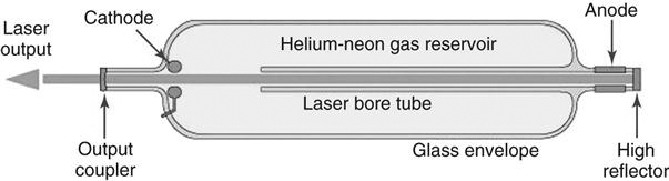
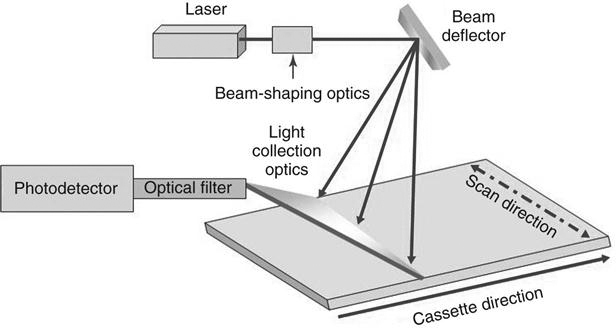
A laser, or light amplification of stimulated emission of radiation, is a device that creates and amplifies a narrow, intense beam of coherent light (Figure 4-8). The atoms or molecules of a crystal such as ruby or garnet or of a gas, liquid, or other substance are excited so that more of them are at high energy levels rather than low energy levels. Surfaces at both ends of the laser container reflect energy back and forth as atoms bombard each other, stimulating the lower energy atoms to emit secondary photons in the same frequency as the bombarding atoms. When the energy builds sufficiently, the atoms discharge simultaneously as a burst of coherent light; it is coherent because all of the photons are traveling in the same direction at the same frequency. The laser requires a constant power source to prevent output fluctuations. The laser beam passes through beam-shaping optics to an optical mirror that directs the laser beam to the surface of the imaging plate (Figure 4-9).
Using the Laser to Read the Imaging Plate.
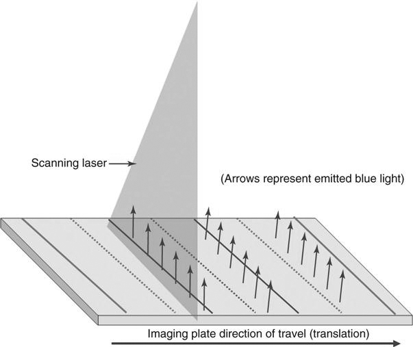
During the reading process, the imaging plate is scanned with a helium laser beam or, in more recent systems, solid-state laser diodes. This beam, about 100 micrometers (µm) wide with a wavelength of 633 nanometers (nm) (or 670 to 690 nm for solid state), scans the plate with red light in a raster pattern and gives energy to the trapped electrons. The red laser light is emitted at approximately 2 electron volts eV, which is necessary to energize the trapped electrons. This extra energy allows the trapped electrons to escape the active layer where they emit visible blue light at an energy of 3 eV as they relax into lower energy levels (Figure 4-10). As the imaging plate moves through or remains stationary in the reader, the laser scans across the imaging plate multiple times. The plate movement through the scanner is known as translation because it moves in a parallel manner at a certain rate through the reader. This scan process produces lines of light intensity information that are detected by a photodetector. The photodetector amplifies the light and sends it to an ADC. The translation speed of the plate must be coordinated with the scan direction of the laser, or the spacing of the scan lines will be affected.
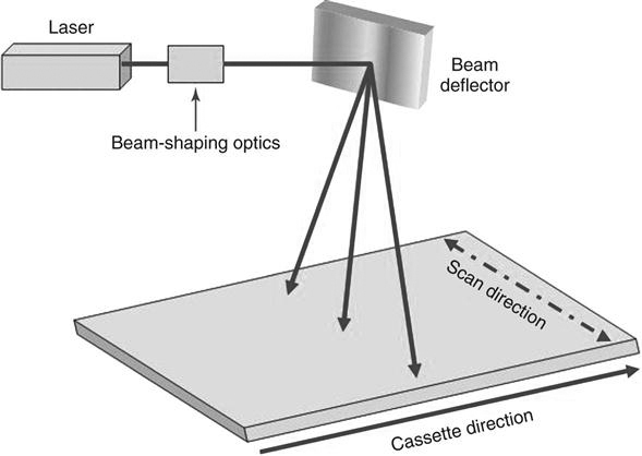
The action of moving the laser beam across the imaging plate is much like holding a flashlight at the same height and moving it back and forth across a wall. The more angled the beam is, the more elliptical the shape of the beam. The same thing happens with the reader laser beam as it scans. This means that if this change in the beam shape were ignored, the output of the screen would differ from the middle to the edges, resulting in differing spatial resolution and inconsistent output signals, depending on the position and angle of the laser beam. To correct this, the beam is “shaped” by special optics that keep the beam size, shape, and speed largely independent of the beam position. A beam deflector moves the laser beam rapidly back and forth across the imaging plate to stimulate the phosphors. Mirrors are used to ensure that the beam is positioned consistently. Because the type of phosphor material in the imaging plate has an effect on the amount of energy required, the laser and the imaging plate should be designed to work together. The light collection optics direct the released phosphor energy to an optical filter and then to the photodetector (Figure 4-11).
Although there will be variances among manufacturers, the typical throughput is 50 cassettes per hour. Some manufacturers claim that a rate of up to 150 cassettes per hour is possible, but based on average hospital department work flow, 50 cassettes per hour is a more realistic expectation.
Digitizing the Signal.
When we talk about digitizing a signal, such as the light signal from a photodetector, we are talking about assigning a numerical value to each light photon. As humans, we experience the world analogically. We see the world as infinitely smooth gradients of shape and color. Analog refers to a device or system that represents changing values as continuously variable physical quantities. A typical analog device is a watch: the hands move continuously around the face and are capable of indicating every possible time of day. In contrast, a digital clock is capable of representing only a finite number of times (e.g., every tenth of a second). The scanning process results in the conversion of the light emitted from the storage phosphor into an electrical signal. The electrical signal is sampled and digitized to represent a specific location within the image matrix and displays as a specific brightness. A matrix is the group of squares that make up the image information.
Each square is called a pixel or picture element. The typical number of pixels in a matrix ranges from about 512 × 512 to 1024 × 1024 for CT but can be as large as 2500 × 2500 for radiography. The more pixels there are, the greater the image resolution for a fixed field of view. The image is digitized both by position (spatial location) and by intensity (gray level). Each pixel contains bits of information, and the number of bits per pixel that define the shade of each pixel is known as bit depth. If a pixel has a bit depth of 8, for example, then the number of gray tones that pixel can produce is 2 to the power of the bit depth, or 28, or 256 shades of gray. Therefore the number of photons detected within the pixel will determine the amount of gray level or bit depth within that pixel. Some PSP systems have bit depths of 10 or 12, resulting in more shades of gray. Each pixel can have a gray level between 1 (20) and 4096 (220). The gray level will be a factor in determining the quality of the image.
Spatial Resolution.
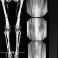
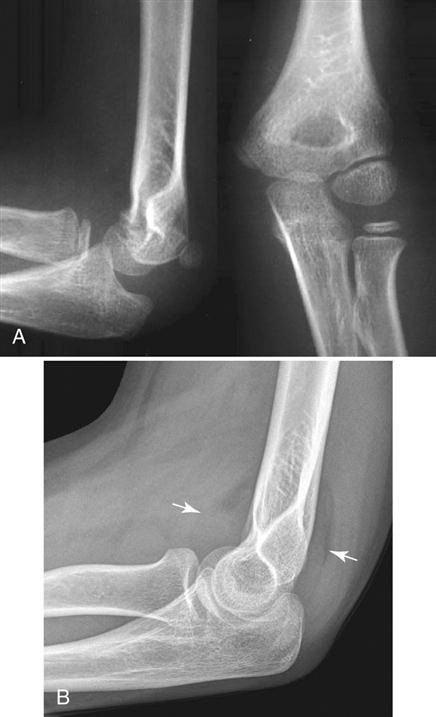
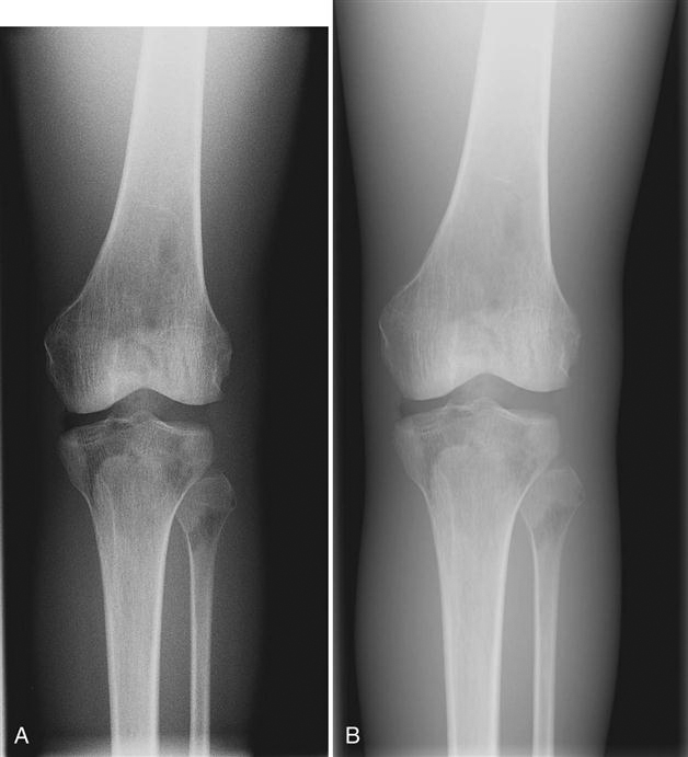
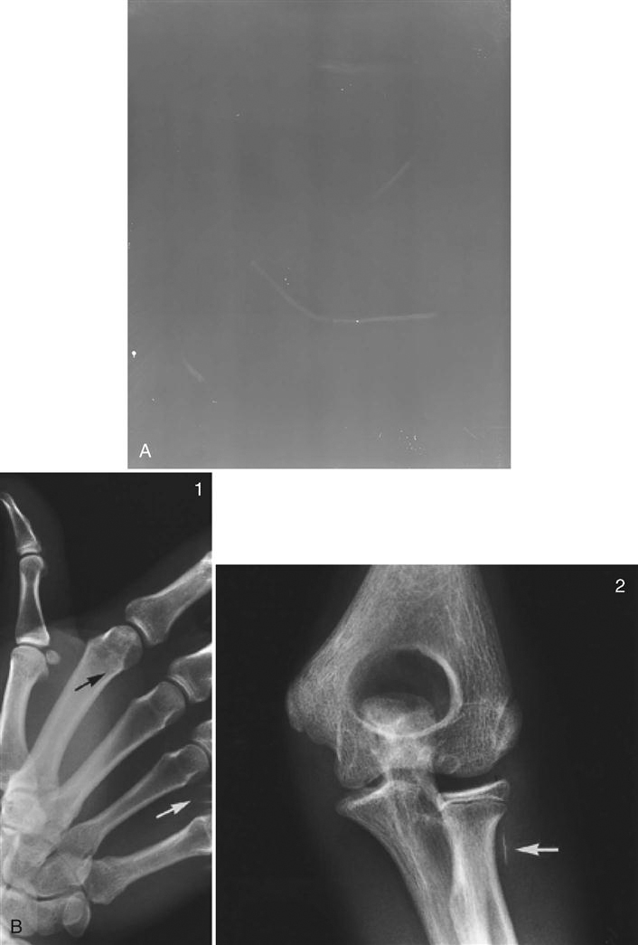
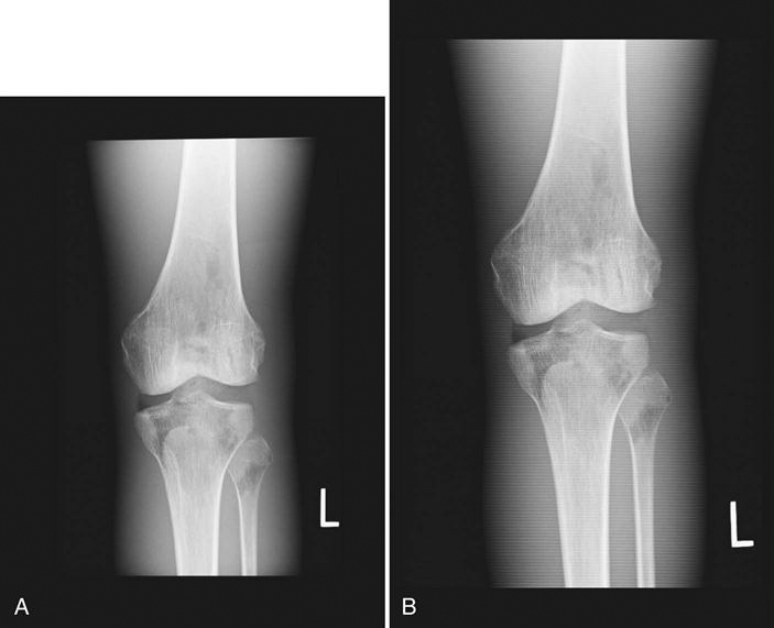
The amount of detail present in any image is known as its spatial resolution. Just as the crystal size and thickness of the phosphor layer determine resolution in film/screen radiography, phosphor layer thickness and pixel size help determine resolution in PSP. The thinner the phosphor layer, the higher the resolution. In film/screen radiography, resolution at its best is limited to approximately 10 line pairs (lp) per millimeter (mm). In general projection radiography PSP imaging, resolution is approximately 2.55 to 5 lp/mm, resulting in less detail. Resolution detail is also affected by the laser beam spot size, translation speed, sampling frequency, and the laser beam sweep in point beam readers. However, because the bit depth, or the number of available shades of gray that can be displayed, is much higher, the difference in resolution is more difficult to discern. More tissue densities on the digital radiograph are seen, giving the appearance of more detail. For example, the fat pads on a lateral elbow are difficult to discern on a film image (Figure 4-12A). Fat pads are a very important sign for the radiologists to see in pediatric elbow fractures. In the digital image, the fat pads are easily seen (Figure 4-12B). This is because of the ability to display more shades of gray, thereby making it possible to visualize more tissues of varying densities; this does not, however, mean that the digital image contains additional detail.
Erasing the Image.
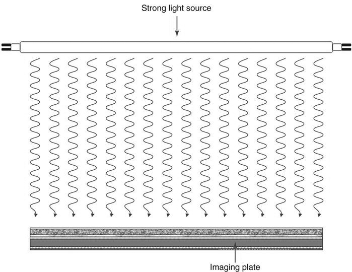
The process of reading the image returns most but not all of the electrons to a lower energy state, effectively removing the image from the plate. However, imaging plates are extremely sensitive to scatter radiation and should be erased to prevent a buildup of background signal. At least once a week the plates should be run under an erase cycle to remove background radiation and scatter. PSP readers have an erasure mode that allows the surface of the imaging plate to be scanned without recoding the generated signal. Systems automatically erase the plate by flooding it with light to remove any electrons still trapped after the initial plate reading (Figure 4-13). Cassettes should be erased before using if the last time of erasure is unknown.
Preprocessing, Processing, and Forwarding the Image.
Once the imaging plate has been read, the signal is sent to the computer where it is preprocessed. The data then go to a monitor where the technologist can review the image, manipulate it if necessary (postprocessing), and send it to the quality control (QC) station and ultimately to the picture archiving and communication system (PACS).
Exposure
Part Selection
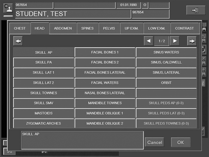
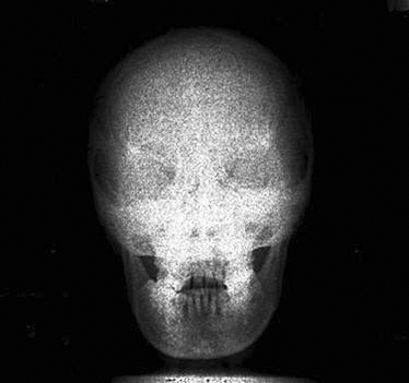
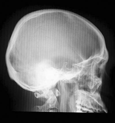
Depending on the type of system being used, the technologist will choose the body part imaged either prior to exposure of the image receptor or after exposure. If the examination room has a PSP housed in the detector in the table or a wall stand, the patient worklist will most likely be in the room’s workstation, which means the technologist may choose the appropriate body part automatically. Always check to make sure the appropriate part has been selected. When using a cassette-based system, the selection of the body part is usually done after exposure and it is imperative that cassettes are kept apart so that the technologist knows which cassette goes with which body part. For example, if a skull examination is to be performed, the technologist would choose “skull” from the workstation menu (Figure 4-14). Selecting the proper body part and position is important for the proper conversion to take place. Image recognition is accomplished through complex mathematical computer algorithms, and if the improper part and/or position is designated, the image may be processed incorrectly and fail to display properly. For example, if a knee examination is to be performed and the examination selected is for skull, the computer will interpret the exposure for the skull, resulting in improper image display (Figure 4-15). The resultant image might appear too dark or too light and it might appear grainy or like it was underexposed. It is not acceptable to select a body part or position other than that being performed simply because it provides a better image. If the proper examination/part selection results in a suboptimal image, then service personnel should be notified of the problem to correct it as soon as possible. Improper menu selections may lead to overexposure of the patient and/or repeated exposure.
Technical Factors
Kilovoltage Peak Selection.
Kilovoltage peak (kVp), milliamperage seconds (mAs), and distance are chosen in exactly the same manner in digital projection systems as in conventional film/screen radiography. Traditionally, kVp was chosen for penetration and tissue type and mAs according to the number of photons required for that body part. kVp values range from 45 to 120 on most digital projection systems. It is not recommended that kVp values lower than 45 or greater than 120 be used because those values may be inconsistent and produce too little or too much excitation of the phosphors. The k-edge of phosphor imaging plates ranges from 30 to 50 kiloelectron volt (keV) so that exposure ranges of 60 to 110 kVp are optimum. However, exposures outside that range are widely used and will depend on the image quality desired. Remember, the process of attenuation of the x-ray beam is exactly the same as in conventional film/screen radiography. It takes the same kVp to penetrate the abdomen with PSP systems as it did with a film/screen system. It is vital that the proper balance between patient dose and part penetration be achieved. A major difference between film/screen and digital receptors is that digital image contrast is no longer dependent on kVp. Sufficient kVp is needed to penetrate the body part; however, higher kVp values can be used, allowing for lower mAs values. The dynamic recording range of digital receptors is much higher than those used in film/screen systems and inherently produces a wide variety of gray values. Contrast is determined by computer processing.
Milliamperage Seconds Selection.
Again, the mAs is selected according to the number of photons needed for a particular part. If there are too few photons, no matter what level of kVp is chosen, the result will be a lack of sufficient phosphor stimulation. When insufficient light is produced, the image is grainy, a condition known as quantum mottle or quantum noise (Figure 4-16). PSP systems typically use automatic exposure controls (AECs), just as many film/screen systems do. When converting from film/screen systems to a PSP system, it is critical that the AECs be recalibrated to the desired exposure indicator.
Equipment Selection
Imaging Plate Selection.
Two important factors should be considered when selecting the PSP imaging cassette: type and size. Most manufacturers produce two types of imaging plates: standard and high resolution. Cassettes should be marked on the outside to indicate high-resolution imaging plates. High-resolution imaging plates contain a thinner phosphor layer as compared to the standard plates. The thinner layer results in greater image sharpness because of the reduced amount of light spreading in more lateral directions. When light spreads laterally, it causes the images to appear somewhat blurry. This occurs with any image capture system that involves the release of light. Typically, high-resolution imaging plates are limited to the smaller cassette sizes and are most often used for extremities, mammography, and other examinations requiring increased detail.
PSP digital images are displayed in a matrix of pixels (Figure 4-17), and the pixel size is an important factor in determining the resolution of the displayed image. As a review from Chapter 2, if the matrix of an imaging system remains constant, as the field of view decreases, the pixel size also decreases and the spatial resolution of the image increases. Therefore the technologist should use the smallest field appropriate for the body part being imaged so that the pixel size will be at its smallest and the spatial resolution will be at its highest. Appropriate image plate selection for the examination also eliminates scatter outside the initial collimation by reducing the amount of imaging plate not being exposed, and this increases contrast resolution.
Grid Selection.
Digital images are displayed in tiny rows of picture elements or pixels. Grid lines that are projected onto the imaging plate when using a stationary grid can interfere with the image. This results in a wavy artifact known as a moiré pattern that occurs because the grid lines and the scanning laser are parallel (Figure 4-18). The oscillating motion of a moving grid, or Bucky, blurs the grid lines and eliminates the interference. Because the PSP systems are more sensitive to low levels of radiation, the use of a grid is much more critical than in film/screen radiography. Appropriate selection of stationary grids reduces this interference as well. Grid selection factors are frequency, ratio, and focus.
Frequency.
Grid frequency refers to the number of grid lines per centimeter or lines per inch. The higher the frequency or the more lines per inch, the finer the grid lines in the image and the less they interfere with the image. Typical grid frequency is between 80 and 152 lines/inch. Some manufacturers recommend no fewer than 103 lines/inch and strongly suggest grid frequencies greater than 150. The higher frequency grids require more x-ray photons to produce an image than lower frequency grids require, therefore the patient will receive a higher dose. In addition, the closer the grid frequency is to the laser scanning frequency, the greater likelihood of frequency harmonics or matching and the more likely the risk of moiré effects.
Ratio.
The relationship between the height of the lead strips and the space between the lead strips is known as grid ratio. The higher the ratio, the more scatter radiation is absorbed. However, the higher the ratio, the more critical the positioning is, so high grid ratio is not a good choice for mobile radiography. A grid ratio of 6 : 1 would be proper for mobile radiography, whereas a 12 : 1 grid ratio would be appropriate for departmental grids that are more stable and less likely to be mispositioned, causing grid cutoff errors.
Focus.
Most grids chosen by radiography departments are parallel and focused. Parallel grids are less critical to beam centering but should not be used at distances less than 48 inches. Focused grids consist of lead strips angled to coincide with the divergence of the x-ray beam and must be used within specific distances using a precisely centered beam.
Collimation
When exposing a patient, the larger the volume of tissue being irradiated, the more scatter will be produced. Whereas the use of a grid absorbs the scatter that exits the patient and affects latent image formation, properly used collimation reduces the area of irradiation and the volume of tissue in which scatter can be created. Collimation is the reduction of the area of beam that reaches the patient through the use of two pairs of lead shutters encased in a housing attached to the x-ray tube. Collimation results in increased contrast resolution as a result of the reduction of scatter. Through postexposure image manipulation known as shuttering, a black background can be added around the original collimation edges, virtually eliminating the distracting white or clear areas (Figure 4-19). However, this technique is not a replacement for proper preexposure collimation. It is an image aesthetic only and does not change the amount or angles of scatter. There is no substitute for appropriate collimation because collimation reduces patient dose.
Side/Position Markers
Anyone who has used digital image processing equipment knows that it is very easy to mark images with left and right side markers or other position or text markers after the exposure has been made. However, we strongly advise that conventional lead markers be used the same way they are used in film/screen systems. Marking the patient examination at the time of exposure not only identifies the patient’s side but also identifies the technologist performing the examination. This is also an issue of legality. If the examination results are used in a court case, the images that include the technologist’s markers allow the possibility of technologist testimony and lend credibility to his or her expertise.
When all of the appropriate technical factors and equipment have been selected, the image receptor may be exposed and then subjected to the reading process. The image will then be displayed. The radiographer must then consider a number of factors: image exposure indicators, image processing modes, and image processing parameters.
Image Data Recognition and Preprocessing
The image recognition phase is extremely important in establishing the parameters that determine collimation borders and edges, and histogram formation. A histogram is a graphic representation of the numerical tone values of an x-ray exposure. All PSP systems have image recognition, and each has a specific name for this process. Agfa uses the term collimation, Carestream uses the term segmentation, and Fuji uses the phrase exposure data recognition. All systems use a region of interest to define the area where the part to be examined is recognized, and the exposure outside the region of interest is subtracted. Each vendor has a specific tool for different situations such as neck, breasts, pediatrics, and hips in which the anatomy requires some special recognition. Please refer to each vendor’s manual to learn their proprietary recognition and processing parameters. The science behind each of these is beyond the scope of this book.
Artifacts
As with film/screen systems, artifacts can degrade images in digital systems. Artifacts are any undesirable densities on the processed image other than those caused by scatter radiation or fog. There are four common types of artifacts (in addition to operator errors that may cause artifacts): imaging plate artifacts, plate reader artifacts, image processing artifacts, and printer artifacts.
Imaging Plate Artifacts
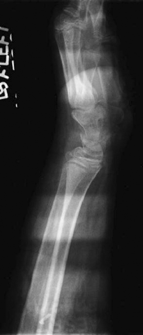
As the imaging plate ages, it becomes prone to cracks from the action of removing and replacing the imaging plate within the reader. Cracks in the imaging plate appear as areas of radiolucency on the image (Figure 4-20). The imaging plate must be replaced when cracks occur in clinically useful areas. Adhesive tape used to secure lead markers to a surface can leave residue behind (Figure 4-21). If static exists because of low humidity, hair can cling to the imaging plate, creating another type of image plate artifact (Figure 4-22).
Backscatter created by x-ray photons transmitted through the back of the cassette can cause dark line artifacts (Figure 4-23). Areas of the lead coating on the cassette that are worn or cracked allow scatter to image these weak areas. Proper collimation and regular cassette inspection help to eliminate this problem.
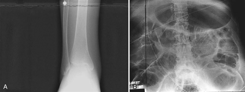
Image Processing Artifacts
Processing artifacts can occur for many different reasons, such as choosing the incorrect processing parameter for a particular part or incorrect sampling of the image file. As discussed previously, it is very important to set appropriate technical factors and choose the correct body part so that the software algorithms will produce the desired image. Poor technique (collimation, grid selection, mAs, kVp, etc.) and positioning can cause these algorithms to misrepresent the image. The technologist must remain aware of all factors that can influence change in the final processed image.
Plate Reader Artifacts
The intermittent appearance of extraneous line patterns can be caused by problems in the plate reader’s electronics (Figure 4-24). Reader electronics may have to be replaced to remedy this problem.
White lines that are parallel to the direction of plate travel are caused by dirt, dust, or scratches on the light guide. Service personnel will need to clean or replace the light guide.
A rare but possible artifact can occur when multiple imaging plates are loaded into a single cassette. In this instance, usually only one of the plates will be extracted, which leaves the other plate to be exposed multiple times. The result is similar to a conventional film/screen double-exposed cassette (Figure 4-25).
Insufficient erasure after an overexposure may result in residual image information being left in the imaging plate before the next exposure. This may also occur if the erasure lamp is in need of repair. The results will vary depending on how much residual image is left and where it is located.
The orientation of a stationary grid relative to the direction of the laser scan is critical to reduce the likelihood of the moiré artifact (Figure 4-26). The grid lines must be perpendicular to the laser scan direction. Moving grids generally do not demonstrate the moiré artifact because the grid lines are blurred out. Vendors have identified the specific grid frequency for stationary grids that will prevent the moiré artifact with their equipment.
Printer Artifacts
Fine white lines may appear on the image because of debris on the mirror in the laser printer. Service personnel will need to clean the printer.
Operator Errors
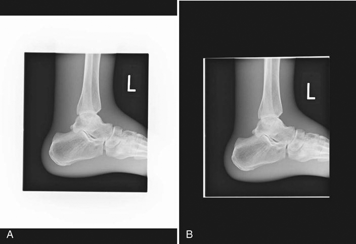
Insufficient collimation can result in an improper calculation of the exposure indicator. This may result in a misrepresentation of the displayed image (Figure 4-27).
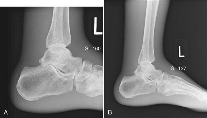
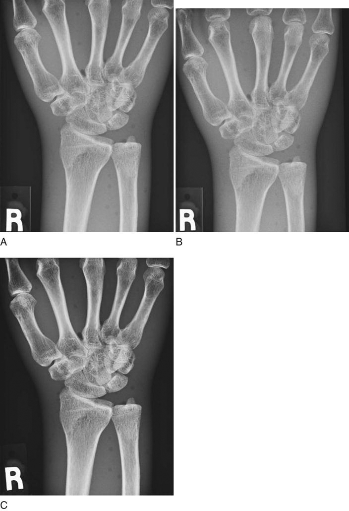
A, Properly collimated lateral ankle. B, Improper collimation resulting in poor histogram analysis. Note the differences in contrast and exposure indices.
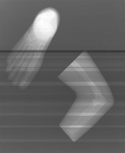
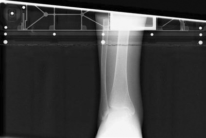
If the cassette is exposed with the back of a cassette toward the source, the result will be artifacts from any hinges or other hardware present on the back of the cassettes. Care should be taken to expose only the tube side of the cassette (Figure 4-28).
Underexposure produces quantum mottle, and overexposure reduces contrast. The proper selection of technical factors is critical for both patient dose, image quality, and to ensure the appropriate production of light from the imaging plate (Figure 4-29).