21 Permanent Pacemaker and Implantable Cardioverter-Defibrillator Implantation
The approach to cardiac pacemaker implantation has evolved during the past half century.1 From the initial epicardial implants of Senning2 and transvenous implantation by Furman and Schwedel,3 cardiac pacemaker implantation has undergone radical changes not only in the implanted hardware but also in the preoperative planning, anatomic approach, personnel, and implantation facilities. The early trend from the epicardial approach to the simpler transvenous cutdown led to the percutaneous technique developed by Littleford and Spector.4 Previously simple preoperative planning, in particular device selection, has become complex. The pacemaker system, both device and electrodes, must be individualized to the patient’s particular clinical and anatomic situation. The implantation procedure, previously the exclusive domain of the cardiovascular surgeon, has also become the purview of the invasive cardiologist. Similarly, the procedure has undergone a transition from the operating room to the cardiac catheterization laboratory or special procedures room. Except in special instances, the luxury of an anesthesiologist has disappeared, with the implanting physician assuming additional responsibilities. Finally, because of concerns about cost containment, the usual in-hospital postoperative observation period has been dramatically reduced or replaced by an ambulatory approach to pacemaker implantation.
Similarly, since Mirowski et al.5 implanted the first implantable cardioverter-defibrillator (ICD) in 1980, its evolution has been comparable with that of the cardiac pacemaker. The initial epicardial ICD placement with an abdominal pocket has given way to a transvenous approach and a pectoral pocket. The surgery initially performed in the operating room exclusively by a cardiovascular surgeon is now carried out by nonsurgeons in the catheterization or electrophysiology laboratory. Also, protracted hospital stays have been replaced by much shorter hospital stays, even outpatient situations. The once-simple ICD device is now much more complex, offering total arrhythmia control as well as backup dual-chamber rate-adaptive pacing.
 Pacemaker Implantation
Personnel
Implanting Physician or Surgeon
It is generally accepted that the pacemaker-implanting physician may be either a thoracic surgeon or an invasive cardiologist.6 At times, the two may even act as a team, with the surgeon isolating the vein and the cardiologist positioning the electrodes. With the current reimbursement structure and the changing economic environment, however, this team approach is rapidly becoming burdensome; in any event, it is frequently unnecessary. Currently, the credentialing for pacemaker implantation procedures poses a dilemma. The trainee in thoracic surgery has ever-diminishing exposure to pacemaker implantation as the procedure becomes more the responsibility of the cardiologist. At the same time, the cardiologist has little or no exposure to proper surgical technique, the use of surgical instruments, and preoperative and postoperative care. Although controversy surrounds the appropriate implantation experience and its length, physicians with limited training and ongoing experience apparently have higher complication rates.7 To remain proficient, the physician should perform a minimum of 12 procedures per year.
In a single-center study of more than 1300 permanent pacemaker implants, Tobin et al.8 reported complications in 4.2% of patients. The economic impact was substantial. Most importantly, there was an inverse relationship between the incidence of acute complication and implanter experience and case volume. Similarly, complications associated with elective generator replacements, revisions, and upgrades have been directly related to operator experience. Harcombe et al.9 found a higher rate of late complications after elective replacements (6.5%) compared with initial implants (1.4%). This higher rate was clearly related to operator inexperience.
There is a definite need for formal training programs specifically designed to teach cardiac pacing.10–12 Such programs should be offered to both cardiologists and surgeons interested in cardiac pacing. The ideal program should be comprehensive and integrated, involving not only all implantations but also follow-up and troubleshooting. To be an effective implanter, the physician must understand the problems of follow-up and troubleshooting. Formal didactic experience and hands-on exposure are necessary. Although a formal, year-long, comprehensive, integrated training program is ideal, consideration of physicians who are out of formal training programs sometimes requires combining more intensive didactic programs with extended, supervised hands-on experience. Training is important for the implantation and nonimplantation aspects of pacing. We see substantially less enthusiasm for the presurgical and postsurgical aspects of pacing. We ardently believe such mastery is crucial to becoming an effective implanter.
Regardless of how physicians have been trained to implant pacemakers, careful review of their training and experience by those granting privileges at the institution will help prevent inadequately trained individuals from performing independent, unsupervised pacemaker implantation. Criteria for adequate training and experience should involve a minimum number of pacemaker procedures, including single-chamber and dual-chamber implantations, lead replacements, pulse generator replacements, and upgrades to dual-chamber from single-chamber systems. Also, some documentable experience in an active pacemaker service clinic should be required.13 An electrophysiology (EP) fellowship is one way of obtaining these skills, and physicians trained as surgeons, pediatricians, radiologists, and cardiologists have access to this training. Credentials can include the EP boards under the jurisdiction of the American Board of Internal Medicine, the Certified Cardiac Device Specialist examination by the International Board of Heart Rhythm Examiners, and cardiothoracic (CT) surgical boards, but only for pacemakers, not ICDs.
Support Personnel
The participation of the manufacturer’s representative as support personnel has always been a subject of debate. This person’s role varies from center to center.14 At one extreme, the representative merely delivers the device and leads to the hospital. At the other extreme, the person is a vital member of the support team, retrieving threshold data, filling out registration forms, and at times, offering technical advice. The latter extreme is particularly true in smaller institutions with less pacemaker activity and in-house support of ICD implantation. A well-trained manufacturer’s representative can be an important member of the support team. An experienced representative dedicated to cardiac pacing and ICD implantation typically has broad experience and a knowledge base in problems unique to the company’s products. Although such a representative of industry can be helpful, this person, no matter how experienced or knowledgeable, should not be considered an acceptable alternative to a knowledgeable, skilled, and experienced physician implanter. If an industrial representative is to be used during implantations for support, hospital approval is advisable.
Implantation Facility and Equipment
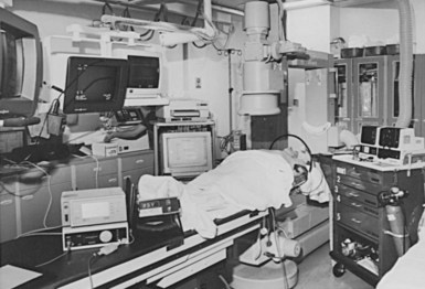
The cardiac catheterization laboratory and special procedures room appear well suited for permanent pacemaker and ICD procedures.15,16 Early concerns about safety and sterility were unfounded, if these issues are appropriately addressed prospectively. Radiologic capabilities are invaluable; high-resolution images, unlimited projections, and angiographic capabilities assist in venous access and electrode placement, as well as in variable image magnification, digital image acquisition, and image imposition techniques and storage. In addition, these facilities tend to be equipped for ready access with all the catheters, guidewires, sheaths, and angiographic materials for special situations. The implantation facility also typically has the most sophisticated physiologic monitoring and recording equipment (Fig. 21-1), offering continuous, surface and endocardial electrical recordings, as well as extensive hemodynamic monitoring capabilities. Again, staffing with qualified cardiovascular nurses and technologists is essential.
The monitoring equipment used for the device procedure is variable. A multichannel electrocardiographic (ECG) recording system is frequently recommended; such systems are able to monitor and record a minimum of three surface electrocardiograms and one intracardiac electrocardiogram.17 From a more practical view, the only requirement is continuous ECG monitoring on an oscilloscope. The ECG pattern need only be clear. Selection of ECG leads should demonstrate adequate atrial and ventricular morphology for defining underlying rhythm, arrhythmias, and atrial and ventricular capture. However, multiple and particularly orthogonal ECG leads are useful to confirm the lead position by ECG morphology.
The surgical instruments for a pacemaker procedure are usually found in a “minor surgical” setup (Fig. 21-2). Depending on the institution, the contents of a minor surgery setup can be overwhelming, particularly for the nonsurgeon implanting physician. The rows of unnamed clamps and retractors would suggest the need to enter a major body cavity. Actually, a pacemaker procedure can be performed efficiently with only a few, well-selected instruments,18 and there are many acceptable variations and personal preferences. Problems can occur, however, with the nonsurgeon implanting physician who is unfamiliar with the instruments and their appropriate use.
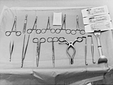
Box 21-1 lists the contents of an acceptable basic surgical tray for pacemaker implantations. The Gelpi and Weitlaner retractors can be used throughout the procedure for improved visual exposure (see Fig. 21-2). The Senn retractor is used for more delicate retraction of tissue edges; one end is L shaped, and the other has tiny claws. Another useful retractor, the Goulet retractor (see Fig. 21-2), can be replaced with a Richardson retractor and is extremely helpful in retraction when creating the pacemaker pocket. Unlike other large retractors, the smooth, scalloped ends of these retractors are gentle to the tissues while affording a generous area of exposure. Army-Navy retractors can also be helpful for this purpose. Other instruments, such as forceps (with or without “teeth”), hemostats, scissors (tissue and other), needle holders, and clamps, are necessary, but their use does not require explanation here. Proper use and care of the instruments are crucial, and replacement of worn-out instruments is mandatory for avoiding frustration, delays, and suboptimal work.
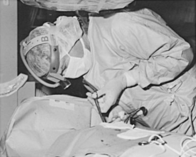
Device procedures performed in the OR typically benefit from excellent lighting. Multiple high-intensity lamps light the surgical field. However, this is not the case for procedures in the CCL or special procedures room, where lighting is frequently marginal. One solution is a high-intensity headlamp, which is extremely useful when creating the pocket and inspecting for bleeders, particularly when one’s head blocks out other light (Fig. 21-3). Using the headlamp can initially be frustrating and requires practice, but once facile, it will become the major light source for creating the pocket. Even in the OR, despite all the lighting, the headlamp can be very helpful.
The electrocautery device can be useful, and some experienced implanters consider it essential to any pacemaker procedure. Its use, however, is controversial.19–21 Historically, using electrocautery equipment for cutting or coagulation during a pacemaker procedure was taboo, with concerns about causing burns at the myocardium-electrode interface, destroying the pulse generator, and damaging the pacemaker leads. The general consensus, however, is that an appropriately grounded electrocautery device is safe when two precautions are taken: (1) active cautery should never touch the exposed proximal pin of the electrode, and (2) use of all electrocautery should cease when the pulse generator is in the surgical field. Cutting with electrocautery expedites pulse generator changes while avoiding the risk of cutting the lead. At times, even in the most experienced hands, a tedious dissection ends with the scalpel or scissors nicking or cutting the electrode insulation. Use of rapid strokes with cautery avoids the buildup of heat, preventing injury to leads. Although experience indicates no important untoward effects on the myocardium if the cautery touches the pulse generator, there is a risk of causing a permanent no-output situation by destroying the pulse generator. This appears particularly true in certain pulse generators or when the battery voltage is well below the replacement indicator. The risk to the patient of a sudden lack of output can be eliminated by placing a temporary pacemaker in pacemaker-dependent patients; this consideration is fundamental to all pacemaker procedures whether or not electrocautery is used.
The pacing system analyzer (PSA) is extremely valuable during pacemaker procedures. PSA circuitry (especially sensing) mimics that of the planned pulse generator and more accurately predicts the performance of the pulse generator, even when stimulators and recorders are available. The early PSAs were simple and designed to measure the pacing and sensing thresholds for single-chamber ventricular pacing. PSAs were unable to perform (or cumbersome performing) the tasks required for atrial and dual-chamber pacing.22 Previously, PSA devices were designed to test both the lead function and the pulse generator. Currently, PSAs can test lead function and usually can adjust the pacing mode so that both the atrial and the ventricular leads can be tested without risking asystole. Modern PSAs can function in any mode and should measure from either chamber, offering a clear digital display as well as extensive programmability. PSAs provide emergency capabilities, including high output, high rate, and often antitachycardia pacing. In addition, hard copy and electronic transfer of data is useful for documentation. An example of a PSA is the Medtronic model 2090 (Fig. 21-4); Table 21-1 summarizes its desirable features. Some of the pacemakers driven by sensors, (e.g., temperature, oxygen) require special additional sensor analysis by a specialized PSA tool. Whether supplied by the institution or the manufacturer, a good PSA is essential.
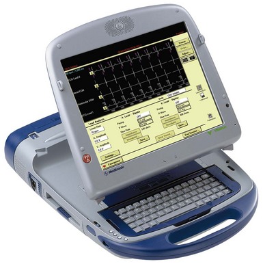
Figure 21-4 Multifunction Medtronic 2090 pacemaker system analyzer.
(From Barold SS: Modern cardiac pacing. Armonk, NY, 1985, Futura, p 444.)
TABLE 21-1 Operating Features of the Medtronic CareLink Programmer 2090 Pacing System Analyzer (Medtronic)
| Parameter | Range |
|---|---|
| Models | VOO, VVI, AOO, AAI, DOO, DDD, VDD, ODO |
| Lower rate: | |
| AOO, AAI, VOO, VVI, DOO | 30-220 |
| DDD, VDD | 30-110 |
| Upper rate | 80-220 |
| Amplitudes (A and V) | 0.1-10.0 V |
| Pulse width (A and V) | 0.02-1.5 msec |
| AV interval: | |
| Sensed | 20-350 msec |
| Paced | 20-350 msec |
| Rapid atrial stimulation | 200-800 min. (ppm) |
| Atrial refractory | 200-500 msec |
| Ventricular refractory | 250 msec |
| Atrial sensitivity | 0.25-20 mV |
| Ventricular sensitivity | 0.5-20 mV |
| Polarity (A and V) | Unipolar/bipolar |
| Atrial Blanking | |
| After atrial pace | 160-300 msec |
| After atrial sense | 160-300 msec |
| After ventricular pace: | |
| VVI/VOO | 150-350 msec |
| DDD/VDD | 200-220 msec |
| After ventricular sense | 150 msec |
| Ventricular Blanking | |
| After atrial pace | 40 msec |
| After ventricular sense | 125 msec |
| After ventricular pace | 200 msec |
| Measurement Parameters | |
| P-wave amplitude | 0.3-30 mV |
| R-wave amplitude | 0.6-30 mV |
| Impedance (A and V) | 200-2499 |
| 2500-4000 | |
| Slew rate | 0.1-4.0 V/s |
| Pacing current | 0.1-25 Max |
| Special Features | |
| Rapid stimulation | AOO, VOO, DOO modes |
| Rates | 180-800 ppm |
| Emergency pacing | VVI rate at 70 at 10 V and 1.5 msec |
A, Atrium/atrial; AV, atrioventricular; V, ventricle/ventricular.
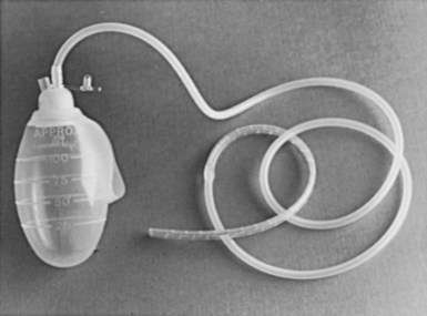
There never seem to be enough spare parts during a pacemaker procedure. Most manufacturers offer service kits containing splice kits, stylets, lead adapters, wrenches, lubricant, lead caps, wire cutters, and so on (Box 21-2). It is advisable to set up a pacemaker cart stocked with all the supplies likely to be needed. This cart should hold (1) a temporary pacemaker tray that contains the materials for venous insertion, as well as the temporary pulse generator and leads, (2) an assortment of sheath sets, dilators, and guidewires, (3) the service kits from the manufacturers of the most commonly used pacemakers, (4) the equipment for lead retrieval, and (5) if they are used, a supply of polyester (Parsonnet; C. R. Bard) pouches (Fig. 21-5). A designated person should make sure supplies are reordered and up to date. Other, lesser used supplies can be obtained from the OR or central supply facility, such as a Jackson-Pratt drain for managing hematomas (Fig. 21-6) and various-sized Penrose drains for tunneling.
Preoperative Planning
Planning a pacemaker procedure is important if the case is to proceed smoothly, starting with patient evaluation, including symptoms, medications, and associated conditions. The physical examination may demonstrate the effects of bradycardia, including altered vital signs, evidence of cardiac decompensation, and neurologic deficits. Anatomic issues potentially affecting the implant can also be uncovered. A key preoperative consideration is documentation of the bradyarrhythmia, through 12-lead electrocardiogram (ECG), Holter monitor, event recordings, or inhospital critical care unit or telemetry unit monitoring. Supporting laboratory data, such as digitalis levels, thyroid parameters, and blood chemical analysis, provide documentation that the bradycardia is not secondary to another condition. The patient evaluation should substantiate the indications outlined by the American College of Cardiology (ACC), American Heart Association (AHA), and North American Society of Pacing and Electrophysiology (NASPE) joint task force.23 The documentation should be readily available and is usually affixed to the patient’s chart.
Inpatient Versus Outpatient Procedure
There is a trend toward performing pacemaker procedures on an ambulatory basis. The experiences at several centers, in both Europe and the United States, have clearly supported the safety and efficacy of this approach.24,25 Concerns about potential complications continue to be expressed.26–28 Questions about lead selection, the timing of discharge, and the intensity of follow-up are frequently raised. In addition, the economic impact has yet to be fully appreciated. Although more ambulatory pacemaker procedures are being performed, this has not been reflected well in the pacing literature. Since the original reports of Zegelman et al.24 and Belott,25 Haywood et al.29 have reported a randomized controlled study of the feasibility and safety of ambulatory pacemaker procedures. Although the study group was small (50 patients), the results were similar to those of one of the authors (PHB). There was good patient acceptance, no evidence of a higher complication rate, and cost savings of £540 (at that time, about $810 U.S.).
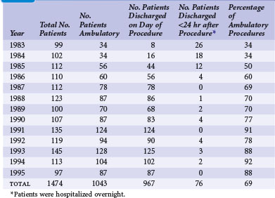
Since the initial report of 181 new pacemaker implants in 1987, our own ambulatory experience continues to be gratifying. During a 13-year span reported in 1996, that experience comprised 1474 pacemaker procedures, 1043 (69%) of which were performed on an ambulatory basis.30 The experience also included pulse generator changes, all of which we have performed on an outpatient basis since 1987. Our experience indicates that 60% to 75% of new pacemaker implantations can be successfully performed as ambulatory procedures (Table 21-2). There have been no additional ambulatory failures, pacemaker-related emergencies, or deaths in the ambulatory procedures. (An ambulatory failure is an implantation that is initiated as an ambulatory procedure, but for which the hospital stay is extended to admitting the patient because of a complication.) The complications encountered in ambulatory cases included one hemothorax detected 2 weeks after discharge, successfully managed by hospitalization and chest tube drainage. Three hematomas were managed on an ambulatory basis with reoperation, control of bleeding, and drain placement. Two small pneumothoraces that did not require chest tubes occurred fortuitously in hospitalized patients who had no planned ambulatory procedure.
These experiences underscore the safety of the ambulatory approach. At present, almost all elective pacemaker procedures (new implantations, electrode repositioning, upgrade procedures, electrode extractions, and pulse generator changes) are done on an ambulatory basis. A simple protocol is used, and the patients often go home 1 to 2 hours after the procedure. They are seen the following day in the pacemaker clinic. Box 21-3 outlines a simple outpatient protocol.
Box 21-3
Outpatient Protocol
In most institutions, patients can remain in the hospital overnight and still be considered outpatients. This practice conforms to the present U.S. Health Care Financing Administration (HCFA) definition of ambulatory surgery for reimbursement in the United States, as follows: “When a patient with a known diagnosis enters a hospital for a specific minor surgical procedure or treatment that is expected to keep him or her in a hospital for only a few hours (less than 24) and this expectation is realized, he or she will be considered an outpatient regardless of the hour of admission, whether or not he or she occupied a bed, and whether or not he or she remained in the hospital past midnight.”31 An important caveat of ambulatory pacemaker procedures is that if there is any doubt or concern about the patient’s well-being, the hospital stay can be extended.
Preoperative Orders
In 2008 the American College of Chest Physicians (ACCP) published evidence-based practice guidelines for the perioperative management of patients receiving antithrombotic therapy,32 including vitamin K antagonists (VKAs) and antiplatelet drugs. ACCP recommends temporary cessation of VKAs and use of perioperative bridging anticoagulation with low-molecular-weight heparin (LMWH) and unfractionated heparin (UFH) for patients at moderate to high risk for thromboembolism and for those with a mechanical heart valve, atrial fibrillation, or venous thrombosis. There is no mention of uninterrupted VKA therapy. For the patient taking antiplatelet drugs who has bare-metal or drug-eluting stents and requires surgery within 6 weeks of stent placement, uninterrupted antiplatelet therapy is recommended. In patients who require temporary interruption of antiplatelets, treatment is stopped 7 to 10 days before surgery. It is recommended that antiplatelet drugs be resumed approximately 24 hours postoperatively. Frequently with pacemaker and ICD procedures, however, antiplatelet therapy cannot be suspended.
Cost controls and managed care can make this process problematic. In addition, despite vigorous attempts at hemostasis, significant hematomas have resulted from the use of heparin. This problem is anecdotal, but in our general experience, the greatest risks for bleeding complications, hemorrhage, and hematoma occur with the use of heparin or platelet antagonists such as aspirin. Having encountered a patient with a devastating thromboembolic complication caused by withdrawal of warfarin, as well as multiple large hematomas from the use of heparin, one of us (PHB) has chosen to perform pacemaker and ICD procedures with the patient still undergoing anticoagulation with oral warfarin. As a rule, patients taking oral anticoagulants have their international normalized ratio (INR) reduced to about 2. With this policy in effect more than 22 years, there have been no devastating hematomas or thromboembolic events. In a recent 13-year retrospective review of 458 device procedures on patients receiving continuous uninterrupted VKA therapy, there were only eight hematomas and no catastrophic hemorrhages or VKA-related deaths.33 This gratifying experience underscores the safety and cost-effectiveness of continuous uninterrupted VKA therapy, which unfortunately remains unaddressed by current guidelines for cardiac implantable electronic device (CIED) procedures.
We believe that pacemaker and ICD procedures can be performed safely with the patient anticoagulated as previously described. Supporting this approach in a 4-year experience, Goldstein et al.34 found no difference in incidental bleeding complications between patients receiving warfarin and those without anticoagulation. No wound hematomas, blood transfusions, or clinically significant bleeding occurred in any patients receiving warfarin. In a later, large series of patients, Giudici et al.35 further substantiated the safety and efficacy of CIEDs without reversing warfarin therapy.
More recently, Ahmed et al.36 demonstrated that interrupting anticoagulation is associated with increased thromboembolic events, and cessation of VKAs with bridging was associated with a higher rate of pocket hematoma and prolonged hospital stays. The authors concluded that continuous uninterrupted VKA therapy with a therapeutic INR was safe and cost-effective. Thal et al.37 compared the incidence of hematoma formation among patients receiving continuous warfarin, aspirin, and clopidogrel therapy. Hematoma formation was rare, even among anticoagulated patients, although an increased incidence was seen in patients receiving dual-antiplatelet therapy. Dreger et al.38 found CIED procedures to be safe in patients on dual-antiplatelet therapy but recommended the use of a drainage system. In patients requiring CRT, Ghanbari et al.39 found uninterrupted warfarin therapy to be a safe alternative to routine bridging therapy, reducing risk of bleeding and shortening hospital stay. More recently, continuing warfarin in patients with a therapeutic INR was shown to be a safe, cost-effective approach compared with cessation of warfarin and bridging anticoagulation.
A new strategy is developing with the release of dabigatran in the United States. This direct thrombin inhibitor has the advantage of a short half-life and obviates the need for INR tracking. The RE-LY study demonstrated its efficacy and safety for patients with atrial fibrillation in comparison to warfarin.40 At this time, no data are available on the impact of dabigatran on perioperative hematomas or the most appropriate perioperative management. However, witholding the medication for 24 hours before the procedure and restarting 24 hours later seems a reasonable initial approach.
Pacemaker Implantation: General Information
Site Preparation and Draping
Currently, many traditional scrubs have been replaced by either a povidone-iodine or a chlorhexidine and alcohol combination. These preoperative skin preparations have the benefit of a single, rapid application. DuraPrep is iodine povacrylex and isopropyl alcohol; ChloraPrep is 2% chlorhexidine and 70% isopropyl alcohol; both offer rapid-acting broad-spectrum protection. Because alcohol-based antiseptic solutions can act as fuel for surgical fires, the skin preparation must be allowed to dry, strictly observing recommended drying times. In addition, it is important to remove the fuel; surgical fires in the OR can result in patient burns and even death.41
The draping process is a matter of personal preference. One of the authors (DWR) applies a sterile, see-through plastic adhesive drape (impregnated with an iodoform solution) over the entire operative area. The other (PHB) uses one or more sterile plastic drapes with adhesive along one side (Fig. 21-7); the adhesive surface is applied from shoulder to shoulder at the level of the clavicle, which serves to create a sterile barrier from the shoulder level down. Depending on the situation, other barriers can be created. In both cases, the plastic drape is used to optimize sterility.
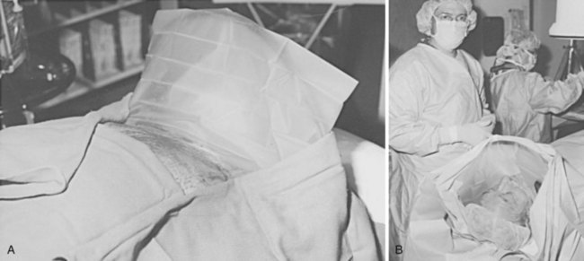
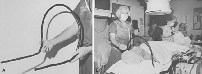
Such an arrangement may not be possible in laboratories, where it interferes with radiographic equipment. Alternatively, the drape may be fixed to the C-arm or image intensifier. This solution is less than optimal; the drapes pull away whenever the C-arm or radiographic table is repositioned, increasing the risks of contamination and breaks in sterile technique. A simple, cost-effective solution consists of a length of common house wire (8/3-gauge Romex) shaped into an arc over the patient’s neck. The ends of the wire are bent at right angles to the arc and tucked under the x-ray table padding at the level of the patient’s shoulders (Fig. 21-8). The weight of the patient’s shoulders supports the wire arc. The wire positioned under the shoulder is checked with fluoroscopy to avoid interference with the radiographic field of view. The house wire is strong enough to keep its shape under the weight of the surgical drape, offering optimal patient comfort and a reliable sterile barrier. There is no interference with the C-arm, and claustrophobia is avoided. The traditional use of a Mayo stand over the patient’s face is problematic because it can cause claustrophobia, makes access to the patient’s airway difficult in an emergency, and may interfere with the x-ray equipment.
Anesthesia, Sedation, and Pain Relief
Most pacemaker procedures are performed with local anesthesia and some form of sedation and pain reliever.42 Local anesthesia alone is inadequate for optimal patient comfort; its effect does not prevent the discomfort associated with creation of the pacemaker pocket. Therefore, the additional combination of a narcotic and sedative is recommended; use of sedation alone is frequently inadequate. The challenge to the physician in charge is to achieve patient comfort without risking oversedation or respiratory depression. If an anesthesiologist or nurse anesthetist is part of the implantation team, patient comfort is usually achieved easily and safely. In this situation, if respiratory depression occurs, the patient can easily be ventilated. When the implanting physician orders the sedation and narcotics, however, the patient must be carefully monitored by the circulating nurse. The medications should be administered slowly.
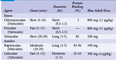
The selection and dose of local anesthetic are also important considerations. A local agent in therapeutic concentration that provides rapid onset of action and sustained duration is desirable. Local agents can be used in combination to achieve the desired effect, such as lidocaine for its rapid onset and bupivacaine for its sustained action. Also, the upper limit of total local anesthetic dose should not be exceeded. Toxic blood levels of local anesthetics can result in profound neurologic abnormalities, including obtundation and seizures. Table 21-3 lists the pharmacologic properties of common local anesthetic agents.
The U.S. Joint Commission on Accreditation of Healthcare Organizations mandates that institutions establish a policy and protocol for patients receiving IV sedation, which would include pacemaker procedures. In essence, the protocol requires formal patient assessment before sedation. Resuscitation equipment must be present at all times in the sedation and recovery areas, and patients undergoing IV sedation must be monitored with pulse oximetry, continuous ECG rhythm monitoring, and automatic blood pressure recordings. Monitoring of the patient should continue for at least 30 minutes after the last IV sedative dose and for at least 90 minutes after intramuscular (IM) sedative administration. There are also strict discharge criteria. Table 21-4 lists common intravenous sedation drug protocols. A North American Society of Pacing and Electrophysiology (NASPE; now Heart Rhythm Society) Expert Consensus developed recommendations and specified minimum training requirements on the use of IV sedation/analgesia by nonanesthesia personnel in patients undergoing arrhythmia-specific diagnostic, therapeutic, and surgical procedures.43

Antibiotic Prophylaxis and Wound Irrigation
The use of prophylactic antibiotics to reduce the incidence of postoperative wound infection in a pacemaker procedure is controversial.44 Importantly, antibiotics are not a substitute for good infection control practices, an adequate surgical environment, and good surgical technique. The use of antibiotics in a pacemaker procedure follows the principle of prophylaxis, in which the risk for infection is low but the morbidity is high.45–47 The selection of antibiotics is based on site-specific flora for wound infection and the spectrum, kinetics, and toxicity of the antimicrobial agent. The risk factors for infection have been well defined. The National Research Council for Wound Classification places the risk for infection from an elective procedure with primary closure at less than 2%. One important consideration is the higher risk for infection in procedures lasting longer than 2 hours.
Now more formally studied, the use of prophylactic antibiotics in the low-risk, high-morbidity group, such as patients receiving pacemakers and defibrillators, appears justified. A meta-analysis of antibiotic prophylaxis showed a significant reduction in the incidence of infection.48 The spectrum of the antibiotic prophylaxis only needs to cover the gram-positive skin flora, primarily Staphylococcus epidermidis and S. aureus. In the case of pacemakers and cardiac procedures, the cephalosporins appear ideal (e.g., 1-2 g of cefazolin IV, pre-anesthesia). Because many institutions have a high incidence of methicillin-resistant S. aureus or S. epidermidis, vancomycin should be considered (e.g., 1 g IV slowly preoperatively). Postoperative doses are left to clinical judgment. Generally, 1 g of either drug may be given intravenously (IV) up to 8 hours postoperatively. Occasionally, the postoperative doses of cephalosporin are given orally for several days.49 A large, prospective, randomized double-blind placebo-controlled trial (RCT) recently validated the efficacy of antibiotic prophylaxis before implantation of pacemakers and defibrillators.50 The trial planned to enroll 1000 patients, but enrollment was terminated at 649 patients by the safety committee. The study demonstrated a significant reduction in infectious complications with antibiotic prophylaxis with 1 g of cefazolin administered before the procedure. Pretreatment with cefazolin reduced the incidence of postprocedural infection (0.64% cefazolin vs. 3.28% placebo; P = .016).
The utility of prophylactic antibiotic has now been well established. Studies have shown that a single preoperative dose of antibiotics is as effective as a 5-day course of postoperative therapy. The prophylaxis should target the anticipated organisms. With complicated or contaminated procedures, additional postoperative coverage is indicated. During prolonged procedures, antibiotics should be readministered every 3 hours. Most importantly, prophylactic antibiotics should be administered within 1 hour before incision and should not be given more than 24 hours after the procedure.51–53
An additional strategy in the prevention of infection is topical antibiotic prophylaxis or antibiotic wound irrigation.54 Controlled trials evaluating the benefit of antibiotic irrigations are lacking. The concept of irrigation is to provide a high concentration of antibiotic at the site of potential infection at the time of contamination. The technique has proved most efficient in the absence of established infection and uses nonabsorbable antibiotics. Historically, aminoglycosides and bacitracin combinations have been used, but regimens vary in number, type, concentration, and duration of antibiotic use. Systemic toxicity with antibiotic irrigation is a major concern. Using large volumes of irrigating solutions with systemic antibiotics can greatly exceed the therapeutic range. The superiority of irrigation over systemic antibiotic administration has never been proved, and given the potential toxicity, caution in its use is recommended. Table 21-5 lists common antibiotic irrigation protocols.
| Agent | Concentration |
|---|---|
| Bacitracin | 50,000 units in 200 mL of saline |
| Cephalothin | 1 g/L of saline |
| Cefazolin | 1 g/L of saline |
| Cefuroxime | 750 mg/L of saline |
| Vancomycin | 200-500 mg/L of saline |
| Povidone-iodine | Concentrated or diluted in aliquots of saline |
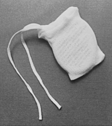
Recently, a novel antibacterial pouch (AIGISx, TyRxPharma) was developed to inhibit biofilms of S. aureus on CIEDs. It consists of a controlled–release polypropylene envelope impregnated with the antibiotics rifampin and minocycline. Its purpose is to reduce the incidence of pocket infections associated with pulse generator changes and other CIED procedures in the patient at high risk for infection; it is not recommended for all patients. An in vitro study demonstrated that the envelope significantly reduced the ability of S. aureus to form biofilms on mock CIEDs.55 Such patients at high risk for infection include the immunocompromised patient with renal failure patients receiving oral anticoagulants, and those undergoing CIED replacement/revision procedures. Bloom et al.56 reported on use of the antibacterial pouch in 624 consecutive CIED procedures of high-risk patients. Device implantation was successful in 621 procedures, with only three major infections. There were no deaths related to the pouch. Use of the pouch was associated with high CIED implantation success with low infection rate in a population at high risk for CIED infection. No data show that the antibiotic pouch reduces the rate of clinical infection in any population.
Anatomic Approaches for Implantation
There are two basic anatomic approaches to the implantation of a permanent pacemaker.57,58 Historically, the first is the epicardial approach, and the second the transvenous approach. The epicardial approach calls for direct application of pacemaker electrodes on the heart. This requires general anesthesia and surgical access to the epicardial surface of the heart. The transvenous approach is usually performed with local anesthesia and IV sedation. Each approach can be accomplished by several unique techniques. Currently, 95% of all pacemaker implantations are performed transvenously. The epicardial approach is generally reserved for patients who cannot undergo safe or effective pacemaker implantation by the transvenous route. The major epicardial techniques involve either applying the electrode(s) directly to a completely exposed heart or performing a limited thoracotomy through a subxiphoid incision (Fig. 21-9). A third technique places the leads by mediastinoscopy. There is even a fourth technique, which combines epicardial and endocardial lead placement. The several techniques used for the transvenous approach involve a venous surgical cutdown, percutaneous venous access, or a combination of both (Box 21-4). The pros and cons of the various approaches and techniques are reviewed here.

A thorough knowledge of the anatomic structures of the neck, upper extremities, and thorax is essential for cardiac pacing (Fig. 21-10). The precise location and orientation of the internal jugular, innominate, subclavian, and cephalic veins are important for safe venous access.59,60 Their anatomic relations to other structures is crucial to avoiding complications.
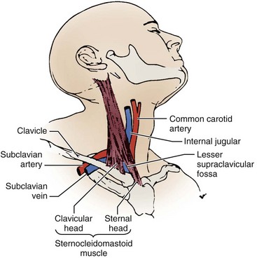
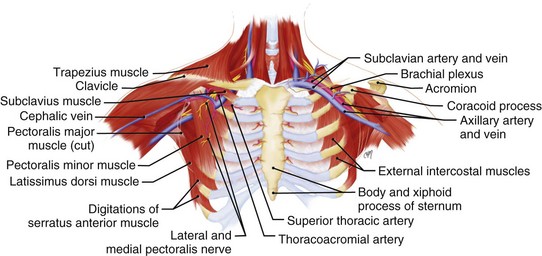
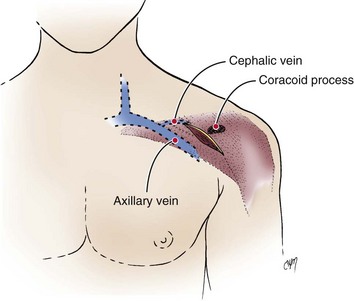
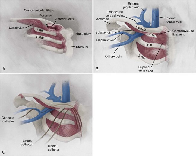
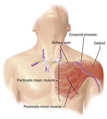
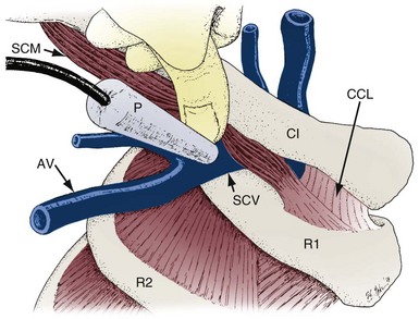
The venous anatomy of interest, from a cardiac pacing point of view, starts peripherally with the axillary vein.60 This large venous structure represents the continuation of the basilic vein and starts at the lower border of the teres major tendon and latissimus dorsi muscle. The axillary vein terminates immediately beneath the clavicle at the outer border of the first rib, where it becomes the subclavian vein. The axillary vein is covered anteriorly by the pectoralis minor and pectoralis major muscles and the costocoracoid membrane. The axillary vein is anterior and medial to the axillary artery, which it partially overlaps. At the level of the coracoid process, the axillary vein is covered only by the clavicular head of the pectoralis major muscle (Fig. 21-11). At this juncture, the axillary vein receives the more superficial cephalic vein.
The internal and external jugular veins have also been used for pacemaker venous access. The external jugular vein is a superficial vein of the neck that receives blood from the exterior cranium and face. This vein starts in the substance of the parotid gland, at the angle of the jaw, and runs perpendicular down the neck to the middle of the clavicle. In this course, the external jugular crosses the sternocleidomastoid muscle and runs parallel to its posterior border. At the attachment of the sternocleidomastoid to the clavicle, the external jugular vein perforates the deep fascia and terminates in the subclavian vein just anterior to the scalenus anticus muscle. The external jugular is separated from the sternocleidomastoid muscle by a layer of deep cervical fascia. Superficially, it is covered by the platysma muscle, superficial fascia, and skin. The external jugular vein can vary in size and may even be duplicated. Because of its superficial orientation, the external jugular vein is less frequently used for cardiac pacing venous access (Fig. 21-12).
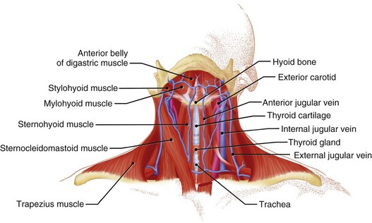
Figure 21-12 Detailed anatomy of the neck demonstrating the relationship of venous anatomy to the superficial and deep structures.
From a venous access perspective, the location of the subclavian vein may vary from a normal lateral course to an extremely anterior or posterior orientation in elderly patients. Byrd61 has described the subclavian venous anatomy of two distinct deformities, both of which make venous access more difficult and hazardous. The first deformity involves a posteriorly displaced clavicle (Fig. 21-13). This is usually seen in patients with chronic lung disease and anteroposterior chest enlargement. Such patients can be identified from the presence of a horizontal deltopectoral groove and the posteriorly displaced clavicle. The second deformity is an anteriorly displaced clavicle (Fig. 21-14), which is found occasionally, especially in elderly women. In this situation, the clavicle is anteriorly bowed or actually displaced anteriorly. It is important that the implanting physician recognize such variations so as to avoid complications such as pneumothorax and hemopneumothorax when using the percutaneous approach.
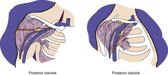
Figure 21-13 Posterior displacement of clavicle.
The deltopectoral groove is in a horizontal rather than an oblique position.
(From Byrd CL: Current clinical applications of dual-chamber pacing. In Zipes DP, editor: Proceedings of a symposium. Minneapolis, 1981, Medtronic, p 71.)
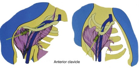
Figure 21-14 Anterior displacement of clavicle.
The deltopectoral groove is nearly vertical.
(From Byrd CL: Current clinical applications of dual-chamber pacing. In Zipes DP, editor: Proceedings of a symposium. Minneapolis, 1981, Medtronic, p 71.)
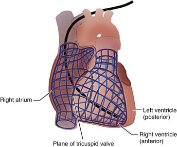
It is assumed that the implanting physician is also completely familiar with the anatomy of the heart and great vessels.62 However, their spatial orientation is at times confusing, particularly with respect to the right atrium (RA) and right ventricle (RV). In the frontal plane, the border of the right side of the heart is formed by the RA. The border of the left side of the heart is composed of the left ventricle. Importantly, the RV is located anteriorly (Fig. 21-15) and is triangular. The apex of the RV is the generally accepted initial “target” for ventricular lead placement, although its location can vary. Its normal location, distinctly to the left of midline, depends on the rotation of the heart, which is affected by various pathologic and anatomic conditions. At times, the apex may be located directly anterior to or even to the right of midline. A lack of appreciation of these variations can lead to considerable difficulty in electrode placement.
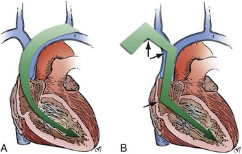
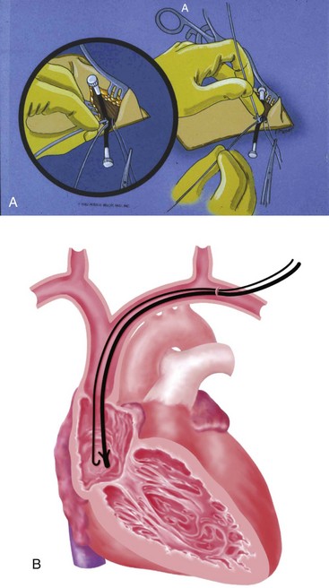
The choice of site for pacemaker implantation is also occasionally important anatomically. This decision is typically made most appropriately on the basis of the patient’s dominant hand, occupation, recreational activities, and medical conditions. The decision should not be made according to the dominant hand of the implanting physician. However, some fundamental differences exist between the anatomy of the right and left sides, which can be frustrating when passing a pacemaker electrode. It seems to be easier for many right-handed implanters to work on the right side of the patient, and vice versa, but from a surgical point of view, catheter manipulation from the right can be a frustrating experience. When entering the central venous circulation from the left upper limb, the pacemaker electrode tracks along a smooth arc to the RV. There are generally no sharp angles or bends (Fig. 21-16, A). Conversely, when approaching from the right, the electrode is forced to negotiate a sharp angle or bend at the junction of the right subclavian and internal jugular veins, where the innominate vein is formed (Fig. 21-16, B). This acute angulation can make the manipulation of the pacemaker electrode difficult when a curved stylet is fully inserted. Another anatomic pitfall occurs when there is a persistent left SVC, making passage to the heart from the left more difficult and, if there is no right SVC, makes passage from the right impossible. These situations are considered later, in the discussion of ventricular electrode placement.
Transvenous Pacemaker Placement
Cephalic Venous Access
The right or left cephalic vein is the most common vascular entry site for insertion of pacemaker electrodes by the cutdown technique.63 The cephalic vein is located in the deltopectoral groove (Fig. 21-17), which is formed by the reflections of the medial head of the deltoid and the lateral border of the greater pectoral muscles. The groove can be precisely located by palpating the coracoid process of the scapula. The dermis along the deltopectoral groove is infiltrated with local anesthetic, encompassing the anticipated length of the incision. A vertical incision is made adjacent to and at the level of the coracoid process. It is extended for about 2 to 5 cm. Care is taken to keep the scalpel blade perpendicular to the surface of the skin. One can create smooth skin edges by making an initial single stroke that carries through the dermis to each corner of the wound. The subcutaneous tissue is infiltrated with local anesthetic along the edges of the incision. The Weitlaner retractor is applied to the edges of the wound, and the subcutaneous tissue is placed under tension. The tension is released by light strokes of the scalpel from corner to corner of the wound in the midline. As the subcutaneous tissue falls away, tension is restored by reapplication of the Weitlaner retractor. This process is continued down to the surface of the pectoral fascia. The fascia is left intact. At this level, the borders of the pectoral and deltoid muscles forming the deltopectoral groove are identified. A Metzenbaum scissors is used to dissect along the groove by separating the muscles’ fibrous attachments. The Weitlaner retractor is reapplied more deeply to retract the muscle. Gradual release of the fascial tissue between the two muscle bodies will expose the cephalic vein.
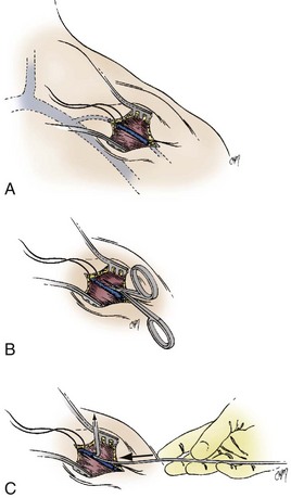
At times, the cephalic vein is diminutive or atretic and unable to accommodate a pacemaker lead. In this case, the cephalic vein can be dissected, centrally, to the axillary vein, and this larger vein catheterized. Once the vein to be catheterized is localized, it is freed of all fibrous attachments. Ligatures are applied proximally and distally (Fig. 21-18, A). The distal ligature is tied and held by a small clamp. The proximal ligature is not tied but is kept under tension with another clamp. An arbitrary entry site is chosen between the two ligatures. The anterior one half of the vein at this site is grasped with a smooth forceps, and the vein is gently lifted. A small, horizontal venotomy is made with iris scissors (Fig. 21-18, B) or a No. 11 scalpel blade. The vein is continuously supported by the forceps. The venotomy is held open by any of several means: a mosquito clamp, forceps, or vein pick. Gentle traction is applied on the distal ligature while tension is released on the proximal ligature. With the venotomy held widely open, the electrode or electrodes are inserted and advanced into the central venous circulation (Fig. 21-18, C).
Subclavian Venous Access
For many years, vascular access has been achieved for many purposes through the use of the Seldinger technique. This simple approach calls for the percutaneous puncture of the vessel with a relatively long, large-bore needle; passage of a wire through the needle into the vessel; removal of the needle; and passage of a catheter or sheath over the wire into the vessel with removal of the wire. An 18-gauge, thin-walled needle 5 cm in length is typically used, although smaller needles are available. These needles come prepackaged with most introducer sets (Fig. 21-19), but an extra supply should be available. The historical problem limiting the use of this technique in cardiac pacing was the inability to remove the sheath from the pacemaker lead. The development of a peel-away sheath by Littleford solved this problem.64–67
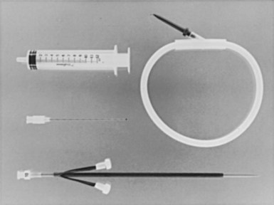
Figure 21-19 Prepackaged introducer set with 18-gauge needle, guidewire, and sheath with rubber dilator.
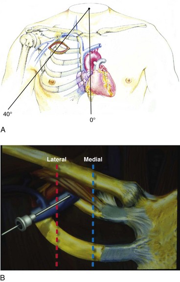
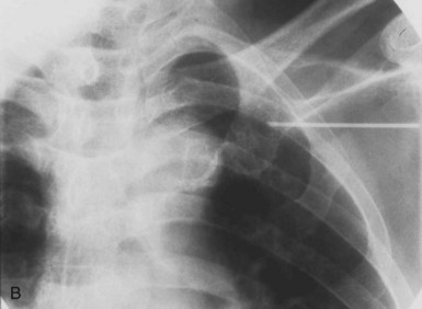
Use of the percutaneous approach requires a thorough knowledge of both normal and abnormal anatomy to avoid complications. The subclavian vein is generally the intended venous structure used for percutaneous venous access in cardiac pacing. Given the previously discussed anatomic variations, the subclavian vein puncture is typically made near the apex of the angle formed by the first rib and clavicle.68 This defines the “subclavian window” (Fig. 21-20). At this puncture site (and after both skin infiltration with local anesthetic and a 1-cm incision at the site, which generally is 1 to 2 cm inferolateral to the point where the clavicle and first rib actually cross), the needle is aimed in a medial and cephalic direction. It is important to make the puncture with the patient in a “normal” anatomic position. The infraclavicular space or costoclavicular angle should not be artificially opened by maneuvers such as extending the arm or placing a towel roll between the scapulae. These maneuvers can open a normally closed or tight space and lead to undesirable puncture of the costoclavicular ligament or subclavius muscle, which in turn can result in lead entrapment and crush. With the patient in the normal anatomic position, access to the subclavian window is medial yet usually avoids the costoclavicular ligament. The more medial puncture and needle trajectory of this approach vastly improves the success rate and dramatically reduces the risks of pneumothorax and vascular injury compared with a more lateral approach. With this medial position, the vein is a much larger target, and the apex of the lung is more lateral. This safer approach is a departure from the conventional subclavian venous puncture, which calls for introduction of the needle in the middle third of the clavicle.
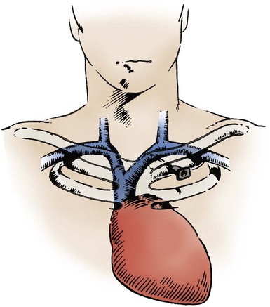
Figure 21-20 The subclavian window.
(From Barold SS, Mugica J: New perspectives in cardiac pacing. Armonk, NY, 1988, Futura, p 257.)
There are legitimate concerns that this medial approach, although safer, results later in higher complication rates and failure rates from conductor fracture and insulation damage.69 It is postulated that the extreme medial position results in a tight fit, subjecting the lead to compressive forces and causing binding between the first rib and the clavicle. Occasionally, this binding can even crush the lead, now called the subclavian crush phenomenon. This phenomenon is more common in larger, complex leads of the in-line bipolar, coaxial design. Fortunately, the incidence of this complication is low. Fyke70,71 first reported insulation failure of two leads placed side by side with use of the percutaneous approach through the subclavian vein, where there was a tight costoclavicular space. This issue has now been addressed thoroughly by two independent groups. Jacobs et al.72 analyzed a series of failed leads for the mechanism of failure, using autopsy studies to correlate the anatomic relationship of lead position to compressive forces (Fig. 21-21). These autopsy data demonstrated generation of significantly higher pressure when leads were inserted in the costoclavicular angle than with a more lateral puncture. The authors concluded that the tight costoclavicular angle should be avoided. Magney et al.73 derived similar data from cadaveric studies and suggested that lead damage is caused by soft tissue entrapment by the subclavius muscle rather than bony contact. This soft tissue entrapment causes a static load on the lead at that point, and repeated flexure around the point of entrapment may be responsible for the damage.
Concern about subclavian crush has also been communicated by pacemaker manufacturers in company literature.74,75 Reduction in lead diameter and perhaps modification of lead technology may be required to eliminate this problem. In the meantime, technique modification appears to be effective at reducing its occurrence. In our experience, if a pacemaker lead feels tight in the costoclavicular space, it is more susceptible to being crushed; it has become our practice at the University of Oklahoma (DWR) to remove the lead from the vein in this situation and repuncture the vein in a slightly different location with reintroduction of the lead. We believe that this practice has reduced the incidence of crush, although more substantial modifications in technique, described later, may be indicated.
Addressing this issue, along with other introducer- or percutaneous-related complications, Byrd76 has described a “safe introducer technique.” This technique consists of a “safety zone” associated with precise conditions ensuring a safe puncture. Byrd also describes a new technique for cannulating the axillary vein if this safety zone cannot be entered. Byrd’s safety zone is defined as a region of venous access between the first rib and the clavicle, extending laterally from the sternum in an arc (Fig. 21-22, A). As a condition for puncture, the site of access must be adequate for ease of insertion to avoid friction and puncture of bone, cartilage, or tendon. With this technique, subclavian vein puncture should never be made outside the safety zone or in violation of the preceding conditions.
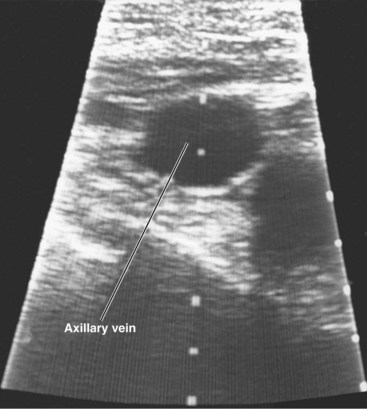
If the safety zone is inaccessible, or the preceding conditions are not met, an axillary vein puncture is recommended. As previously mentioned, the axillary vein is actually a continuation of the subclavian vein after it exits the superior mediastinum and crosses the first rib. The axillary vein is also frequently referred to as the extrathoracic portion of the subclavian vein (Fig. 21-23).
Axillary Venous Access (see Box 21-4)
The axillary vein approach is actually not new. In 1987, on the basis of cadaveric studies that established reliable surface landmarks, Nichalls77 and Taylor and Yellowlees78 reported this approach as an alternative safe route of venous access for large, central lines. The axillary vein has a completely infraclavicular course (Fig. 21-24). The needle path must always be anterior to the thoracic cavity, avoiding risks of pneumothorax and hemothorax.
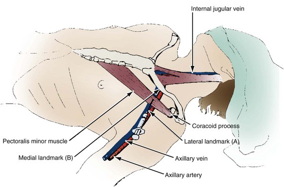
Figure 21-24 Nichalls’ landmarks for axillary venipuncture.
(From Belott PH, Byrd CL: Recent developments in pacemaker implantation and lead retrieval. In Barold SS, Mugica J, editors: New perspectives in cardiac pacing. Armonk, NY, 1991, Futura.)
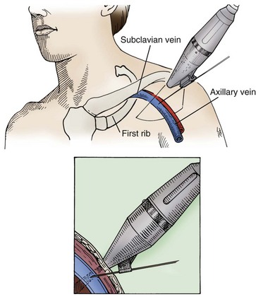
In the technique described by Byrd, the axillary vein puncture is performed as a modification of the standard subclavian vein procedure without repositioning of the patient (Fig. 21-25; see also Fig. 21-20, B). The introducer needle is guided by fluoroscopy directly to the medial portion of the first rib. The needle is held perpendicular to, and touches, the first rib. The needle, held perpendicular to the rib, is “walked” laterally and posteriorly, touching the rib with each change of position. Once the vein is punctured, as indicated by aspiration of venous blood into the syringe, the guidewire and the introducer are inserted with use of standard technique. This approach essentially guarantees a successful and safe venipuncture without compromising the leads if the conditions for entering the safety zone are adhered to and if the first rib is touched to maintain orientation. The only complication not prevented by this approach is inadvertent puncture of the axillary artery.
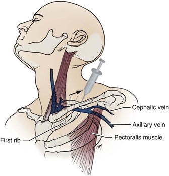
Figure 21-25 Byrd’s technique for access to extrathoracic portion of subclavian vein.
Sequential needle punctures are walked posterolaterally along the first rib.
(From Belott PH, Byrd CL: Recent developments in pacemaker implantation and lead retrieval. In Barold SS, Mugica J, editors: New perspectives in cardiac pacing. Armonk, NY, 1991, Futura.)
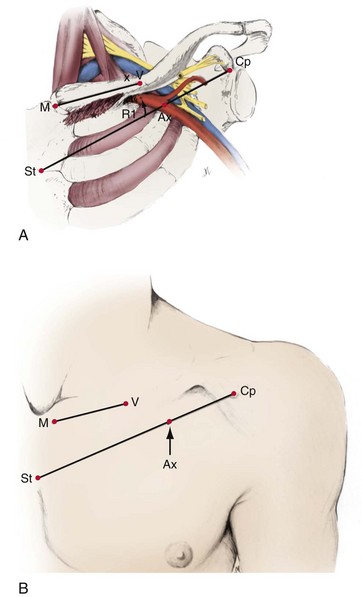
Byrd79 has reported success in a series of 213 consecutive cases in which the extrathoracic portion of the subclavian vein (axillary vein) was successfully cannulated as a primary approach. Magney et al.80 subsequently reported a new approach to percutaneous subclavian venipuncture to avoid lead fracture. This technique is very similar to Byrd’s and uses extensive surface landmarks for venipuncture (Fig. 21-26). It involves puncture of the extrathoracic portion of the subclavian vein. Magney et al.80 define the location of the axillary vein as the intersection with a line drawn between the middle of the sternal angle and the tip of the coracoid process. This is generally near the lateral border of the first rib.
Belott81 described blind axillary venous access using a modification of the Byrd and Magney recommendations. In this technique, the deltopectoral groove and coracoid process are primary landmarks and are palpated, and the curvature of the chest wall is noted (Fig. 21-27). An incision is made at the level of the coracoid process. It is carried medially for about 6.25 cm (2.5 inches) and is perpendicular to the deltopectoral groove (Fig. 21-28). The incision is carried to the surface of the pectoralis major muscle. The deltopectoral groove is visualized on the surface of the muscle. The needle is inserted at an angle 45 degrees to the surface of the pectoralis muscle and parallel to the deltopectoral groove and 1 to 2 cm medial (Fig. 21-29). At present, the blind venous access approach has been abandoned (PHB) for this first rib approach, because it reduces the risk of pneumothorax to zero.82 Critical to its success is the ability to identify the first or second rib on a radiograph. In addition, if the first rib is poorly visualized or set too far under the clavicle, one can always use the second rib in a similar fashion.
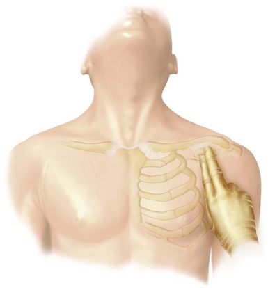
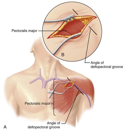
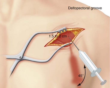
Figure 21-29 Needle and syringe trajectory and angle with respect to the deltopectoral groove and chest wall.
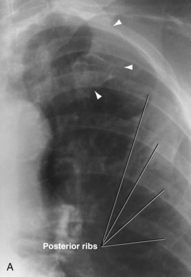
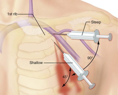
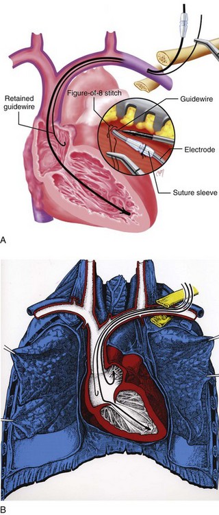
To access the axillary vein using the first rib, the image intensifier is pulled over to the incision. The first rib is then identified, usually the most superior U-shaped rib (Fig. 21-30, A). The ribs seen traversing medial to lateral in an inferior direction are posterior. Identifying the first rib fluoroscopically is critical. If the operator misinterprets a posterior rib as the first rib, a percutaneous stick will result in a pneumothorax or access of undesired cardiopulmonary structures. The first step in accessing the axillary vein using the first rib is to place the 18G percutaneous needle and syringe on top of the pectoralis major muscle in the superior aspect of the incision. Using fluoroscopy, the needle tip is placed in the middle of the first rib (Fig. 21-30, B). The angle of the syringe and needle is gradually increased as the needle is advanced through the pectoralis major muscle. The foreword motion of the percutaneous needle and syringe should allow the tip of the needle to be maintained fluoroscopically over the body of the first rib. To maintain first rib orientation, a rather steep angle is generally required. The needle advancement is continued until the first rib is struck. In essence, this maneuver is attempting to pin the axillary vein to the first rib (Fig. 21-31). Once the first rib is touched, the needle and syringe are slowly withdrawn under suction until the vein is entered, as indicated by a flash of blood in the syringe. If the first pass is unsuccessful, the needle and syringe are moved medially or laterally, and the maneuver is repeated until successful. Once the vein is entered, the guidewire is passed and the sheath applied per standard technique. If the needle is advanced toward the first rib through tissue or muscle without the needle tip initially visualized fluoroscopically directly over the first rib, this shallow angle may result in the needle passing between an intercostal space. This will result in a pneumothorax. It is recommended that a figure-of-eight stitch be applied around the needle puncture for hemostasis and the retained-guidewire technique used for multiple lead placement.
A number of techniques can facilitate access to the axillary vein. Varnagy et al.83 describe a technique for isolating the cephalic and axillary veins by introduction of a radiopaque J-tipped polytetrafluoroethylene guidewire through a vein in the antecubital fossa under fluoroscopic control (Fig. 21-32). The metal guidewire is then palpated in the deltopectoral groove or identified with fluoroscopy. This guides the subsequent cutdown or puncture of the vessel with fluoroscopy. A cutdown can be performed on a vein, and the intravascular guidewire pulled out of the venotomy to allow the application of an introducer. If a percutaneous approach is used, the puncture can always be extrathoracic, using fluoroscopy to guide the needle to the guidewire. This technique offers the benefit of rapid venous access while avoiding the risk of pneumothorax associated with the percutaneous approach.
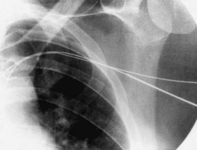
Figure 21-32 Percutaneous access to the axillary vein using a J wire introduced by means of the antecubital vein for reference.
Contrast venography, described subsequently, can also be used for axillary venous access. The venous anatomy can be observed with contrast fluoroscopy in the pectoral area and, if possible, recorded for repeat viewing. The needle trajectory and venipuncture are guided by the contrast material in the axillary vein. Laboratories with sophisticated imaging capabilities can create an image “mask” (see later). Spencer et al.84,85 reported the use of contrast material for localizing the axillary vein in 22 consecutive patients. Similarly, Ramza et al.86 demonstrated the safety and efficacy of using the axillary vein for placement of pacemaker and defibrillator leads when guided with contrast venography. They successfully accomplished lead placement in 49 of 50 patients using this technique.
Access to the axillary vein can also be guided by Doppler flow detection and ultrasound techniques. Fyke87 describes use of an extrathoracic introducer insertion technique in 59 consecutive patients (total of 100 leads) with a simple Doppler flow detector. A sterile Doppler flow detector is moved along the clavicle. Once the vein is defined, the location and angulation of probe are noted, and the venipuncture is carried out (Fig. 21-33). Care is taken to avoid directing the Doppler beam beneath the clavicle. Gayle et al.88 have developed an ultrasound technique that directly visualizes the needle puncture of the axillary vein.89 A portable ultrasound device with sterile sleeve and needle holder are used. The ultrasound head is placed over the skin surface in the vicinity of the axillary vein. Once the vein is visualized, the puncture technique can be used. This technique has been used with considerable success for both pacing and defibrillator electrodes. There have been no reports of pneumothoraces. This technique can be carried out transcutaneously or through the incision on the surface of the pectoralis muscle (Figs. 21-34 and 21-35).
In summary, the axillary vein has become a common venous access site for pacemaker and defibrillator implantations, because of concerns about subclavian crush and the requirement for insertion of multiple electrodes for dual-chamber pacing and at least one large complex electrode for transvenous defibrillation. A number of reliable techniques are available for axillary venous access (see Box 21-4). Given the recent interest in the axillary vein, it is recommended that the implanting physician become thoroughly familiar with the relevant anatomy. The interested physician must visit the anatomic laboratory to refresh and review the regional anatomy and surface landmarks. There is also some concern that lateral access of the axillary vein can result in acute bends in the lead. This can result in increased lead stress and potential for fracture or lead damage, because in its lateral aspect, the axillary vein is a much deeper structure as it transitions to the subclavian vein. It is this deeper venous access that results in acute lead angulation. This is particularly true for those who use the second rib as a landmark for axillary venous access.
For a more conventional subclavian vein approach, Lamas et al.90 have even recommended fluoroscopic observation of the needle trajectory for achieving a successful and safe subclavian vein puncture. They initially identify the clavicle on the side of the puncture, noting its course and landmarks. The skin is entered about 2 cm inferior to the junction of the medial and lateral halves of the clavicle, aiming with fluoroscopic guidance for the caudal half of the clavicular head.
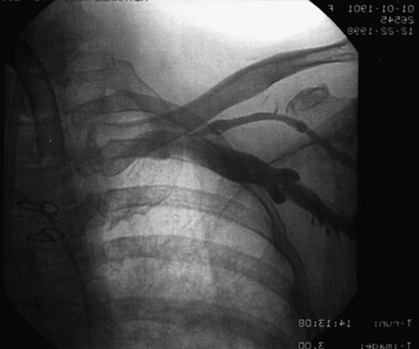
As with axillary vein access techniques, the subclavian puncture can be facilitated by the use of contrast venography.91 It is helpful in patients with potentially difficult venous access. Venography should be considered before any puncture in which venous patency is in doubt or abnormal anatomy is suspected. As described by Higano et al.,91 a venous line is established in the arm on the side of planned pacemaker venous access. The line should be reliable and 20 gauge or larger. One must ensure that the patient does not have an allergy to radiographic contrast material. The contrast injection is performed by a nonsterile assistant. From 10 to 50 mL of contrast material (nonionic or ionic) is injected rapidly into the IV line in the forearm, followed by a saline bolus flush. The contrast medium moves slowly in the peripheral venous system and can be moved along by massage of the arm through or under the sterile drapes. The venous anatomy is observed with fluoroscopy in the pectoral area and, if possible, recorded for repeated viewing (Fig. 21-36). The needle trajectory and venipuncture are guided by the contrast material in the subclavian vein. In more sophisticated radiologic laboratories, a mask or map can be made for guidance after the contrast medium has dissipated. The process can be repeated as necessary.
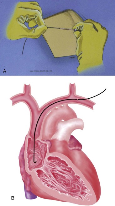
When proceeding with a percutaneous venipuncture, one should hold the syringe in the palm of the hand with the dorsal aspect of the hand resting on the patient. This gives support and control as the needle is advanced. With the needle held this way, tactile sensation is enhanced, and one can frequently feel the needle enter the vein. Once the vessel is entered, the guidewire is inserted, and the tip advanced to a position in the vicinity of the right atrium (Fig. 21-37). We prefer to use J-shaped or curved-tip guidewires for safety reasons. If resistance is encountered, the wire is withdrawn slightly and advanced again. If the resistance persists, the wire position is checked with fluoroscopy. If the wire just outside the tip of the needle appears coiled, it is probably extravascular. In this case, the wire and needle are removed, and a new venous puncture is carried out. Extremely rarely, one may not be able to re-enter the vein. This may be due to collapse of the vein by a resultant hematoma caused by a small tear in the vein from the misdirected guidewire. In this case, one should probably proceed to an alternative approach or site of venous access, to avoid an unnecessary waste of time and a higher risk of pneumothorax with multiple subsequent unsuccessful percutaneous punctures.
Once the wire is successfully positioned in the vein, some implanters place a purse-string suture in the tissue around the point of entry of the wire into the tissue. Alternatively, a figure-of-eight stitch can be applied (Fig. 21-38). This step can be helpful later for hemostasis.92 Such sutures require that an incision be made beginning at the needle and extending inferiorly to the depth of the pectoral fascia.
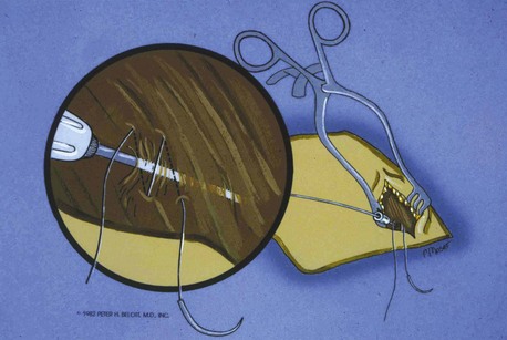
Figure 21-38 Placement of the figure-eight stitch to enhance hemostasis.
(From Belott PH: Retained guide wire introducer technique, for unlimited access to the central circulation. Clin Prog Pacing Electrophysiol 1:59, 1983.)
After the sheath has been successfully passed over the guidewire to the vicinity of the SVC, the dilator and guidewire can be removed, and the lead advanced through the sheath. Problems can be encountered when the lead is passed through the sheath. Occasionally, in the process of introduction, the sheath buckles at a point in the venous system where there is a bend93 (Fig. 21-39). This usually occurs after the removal of the dilator. It can also occur if the sheath is advanced against the lateral wall of the SVC; if a buckle occurs, the lead will not pass this point. Forcing the lead can result in damage to the cathode and insulation. This kink can usually be observed on fluoroscopy. There are several solutions to this problem. If the guidewire and dilator have both been removed, both can be replaced down the sheath. The dilator with wire inside is now functioning not only as a way to stiffen the sheath, but also as a tip occluder, and both can be passed back down the sheath. The tapered tip of the dilator will straighten the buckle. One can change the position of the buckle point by slightly advancing or retracting the sheath. The dilator is removed, but the guidewire can be retained. It is hoped that the retained guidewire will act as a stent, preventing the buckle from recurring and thus allowing the electrode to pass completely down the sheath. Another option when buckling of sheath occurs is to advance the lead to within a couple of centimeters of the buckle and then slowly withdraw the sheath, holding the lead position stationary. The sheath, including the buckle point, may occasionally be easily withdrawn over the tip of the lead, and the lead can be cautiously advanced. In this situation, it is sometimes necessary to withdraw the stylet from the tip of the lead to allow easy advancement of the lead beyond the buckle point. Inexperienced implanters should be cautious with this latter technique, however, because it may damage the distal electrodes.
The risk of air embolization is substantial with the percutaneous approach; using the Trendelenburg position is recommended. With the shift of the pacemaker procedure to the CCL or special procedures room, however, it is often impossible to place the patient in Trendelenburg position. Consequently, the patient is at greater risk for air embolization if the percutaneous approach is used. It is most important that the implanting physician be aware of the danger and take steps necessary to avoid this potential catastrophe (Box 21-5). The physician must be aware that removal of the sheath dilator in a patient who is fasting and somewhat volume depleted can rapidly cause aspiration of large quantities of air. Because the luxury of the Trendelenburg position is unlikely to be available in the CCL, other steps must be taken. Contrary to some practices, the patient about to undergo pacemaker implantation should be kept in a euvolemic or even a relatively volume-overloaded state if there is no contraindication. Instead of IV fluids at a restricted rate, adequate hydration should be maintained. We routinely place a large, wedge sponge under the patient’s legs to enhance blood return and increase central venous pressure.
Box 21-5
Prevention of Air Embolism during Permanent Pacemaker Procedures
A variation of the introducer technique involves retaining the guidewire. Instead of being removed together with the dilator, the guidewire is left in place so that the lead is passed through the sheath alongside it. The sheath is subsequently removed and peeled away (Fig. 21-40). Occasionally, the size of the electrode and the sheath precludes the passage of the lead alongside the guidewire. In this case, the guidewire is removed, the lead passed down the sheath, and the guidewire reinserted behind the electrode. This maneuver succeeds because it is the electrode that will not pass alongside the guidewire, whereas the lead body is thinner and leaves enough room in the sheath to accommodate the guidewire. Certain leads (especially those with bipolar electrodes) and sheath combinations are too tight to allow passage of both the electrode and guidewire. In this case, a larger sheath can be used.
Methods of Dual-Chamber Venous Access
The percutaneous approach is particularly useful in dual-chamber pacing. It has eliminated the earlier dilemma of needing to introduce two leads into a vein exposed by cutdown that may barely accommodate a single lead, with the resultant need for a second venous access site. Box 21-6 lists the options for dual-chamber venous access. For dual-chamber pacing, at least four methods that involve the percutaneous approach are described here. The first three can be used with any of the previously described percutaneous approaches.
Two Separate Percutaneous Sticks and Use of Two Sheath Sets
Parsonnet et al.94 described the insertion of two sets of permanent electrodes, with a third set for a cardiac venous lead. Two separate punctures raise the risk of complications related to the venipuncture process, and not finding the vessel the second time is also possible. The advantage of this method is that even relatively large bipolar leads can be easily and independently manipulated after introduction, with little risk of unwanted and frustrating movement of the other lead.
One Percutaneous Puncture and Use of Large Sheath with Passage of Both Electrodes
The passage of two electrodes down one sheath reduces the risk of making two separate punctures.95,96 However, the large sheath may increase the risk of substantial air embolism and blood loss. In our experience, there is also frequent frustration from lead interaction, entanglement, and dislodgement.
Retained-Guidewire Technique
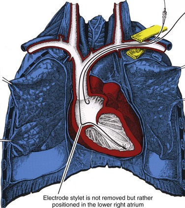
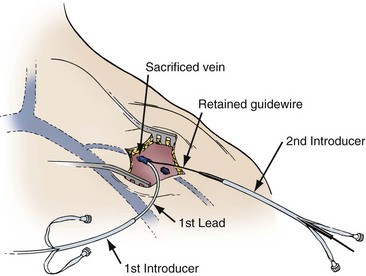
The retained-guidewire technique can be used alone as a method for the introduction of two leads or can be incorporated into any of the other techniques for the introduction of two leads.97,98 One of the authors (PHB) uses this technique alone, preferentially for dual-lead introductions, and the other (DWR) uses it as backup in combination with the two separate puncture techniques described previously. This approach is most desirable because it provides unlimited access to the central circulation. The implanter using this technique can easily add and exchange leads, an important advantage in dual-chamber pacing, in which the initially chosen atrial lead is occasionally unacceptable for a given anatomic situation. Less frequently, it is also helpful to be able to exchange ventricular leads. When using the retained-guidewire technique for dual-chamber implantation, one usually positions the ventricular electrode first, a practical and safe step. The ventricular electrode can be more easily stabilized and is less susceptible to dislodgement from positioning of the second electrode. One can then stabilize the ventricular electrode by leaving the stylet pulled back in the lead in the vicinity of the lower right atrium (Fig. 21-41). A stitch should be placed proximally around the lead and suture sleeve and secured about 1 to 2 cm from the puncture site in the subcutaneous tissue on the surface of the pectoral muscle.
After ventricular electrode stabilization, a second sheath can be advanced over the retained guidewire. The atrial electrode is introduced, positioned, tested, and secured. Alternatively, the retained-guidewire technique can be employed to introduce both leads into the SVC, right atrium, or inferior vena cava (IVC) areas before positioning either electrode. This procedure may reduce risk of dislodgement of the initially positioned electrode caused by introduction of the second sheath. Regardless of variation, the guidewire is removed only after all leads have been placed and tied down (Fig. 21-42). A purse-string or figure-of-eight suture can be tied loosely to achieve hemostasis around the puncture site.
Sheath Set Technique with Cutdown Approach
Ong et al.99 described a modified cephalic vein guidewire technique for the introduction of one or more electrodes. The Ong-Barold technique appears to be a safe and reasonable alternative to the percutaneous subclavian vein introducer technique.100 It is particularly recommended for the inexperienced implanter. It is also recommended for use in patients at high risk of complications with the percutaneous approach, as well as when the percutaneous approach is anticipated to be difficult if not impossible.
This technique requires an initial cutdown to the cephalic vein as previously described. For a single-lead introduction, the size of the vein is irrelevant. All that is necessary is the introduction of the guidewire, which is accomplished with needle puncture under direct visualization. The cephalic vein is sacrificed because it seems to invaginate into the subclavian vein with advancement of the sheath set over the guidewire (Fig. 21-43). Hemostasis is achieved with pressure or the application of a figure-of-eight stitch. Despite the sacrifice of the cephalic vein, no venous complications have been reported. When two leads are required, the retained-guidewire technique and sheath set technique can be used in this approach.
Complications of Percutaneous Venous Access and Blind Subclavian Puncture
The safety and efficacy of the blind subclavian puncture remain controversial with respect to the incidence of serious complications and even death (Box 21-7). Parsonnet and Bernstein101 reported a 0.4% incidence of serious complications in a survey of 11 implanting physicians in a review of 2500 cases. Furman102 showed the remarkable efficiency of the cutdown approach for single-chamber and dual-chamber pacing, particularly with unipolar leads. The cutdown technique, however, was less useful for the introduction of bipolar leads via a single cephalic vein. Furman103 reported no vascular or pleural complications in a large series of 3500 cases in which the cutdown approach was used for single-chamber and dual-chamber pacemaker implantations. Parsonnet et al.7 analyzed the pacemaker implantation complication rates with respect to contributing factors. They reviewed 632 consecutive implantations over a 5-year period performed by 29 implanting physicians at a single institution. There were 37 perioperative complications. Complications were analyzed in regard to experience of the implanting physician. Percutaneous venous access was associated with the highest complication rate and contributed significantly to a 5.7% overall complication rate. When the complications related to the percutaneous approach were excluded, the complication rate dropped to a more acceptable 3.5%. The highest complication rate was among physicians implanting fewer than 12 pacemakers a year and with the least pacing experience.
In reviewing complications of pacemaker insertion, Sutton and Bourgeois104 noted an overall 1% incidence of subclavian vein puncture leading to pneumothorax. Arterial puncture occurred more often, at a rate of about 3%, but generally was not associated with any morbidity. Similarly, in their analysis of thrombotic complications, axillary vein thrombosis was rare, occurring in 0.5% to 1% of cases. Interestingly, partial venous obstruction in the great veins was almost the rule and occurred to some degree in up to 100% of cases. Clinical pulmonary embolism, however, was extremely rare. As a rule, partial or silent inconsequential thrombosis is considered extremely common but generally of no clinical significance.105
Placement of the Ventricular Electrode
Many techniques for placing the ventricular electrode are described throughout the published pacing literature,105 essentially reflecting the approach with which any particular clinician has facility. There is no one correct technique. Ventricular electrode placement is largely independent of the route of venous access. The implanting physician must draw on experience to deal with the variety of situations that will be encountered in any given patient. In time, implanters develop their own technique. The fundamental principles and maneuvers are common to all: (1) simultaneous manipulation of lead and stylet, (2) documentation of passage into the right side of the heart, and (3) manipulation of the electrode into the apex or other desired location in the right ventricle.
The fluoroscope should be used for the entire lead positioning process and can be used initially in the posteroanterior (PA) projection or in the right anterior oblique (RAO) projection. The latter helps delineate the RVA to the left of the spine and toward the left lateral chest wall. The RAO projection creates the illusion that the “mind’s eye” expects, with respect to the location of the RVA, specifically, that the RV apex is near the apex of the cardiac silhouette. In many patients, however, the RVA tends to be more anterior than leftward. Much time can be wasted trying to position a ventricular electrode to the left of the spine toward the apex of the cardiac silhouette (in the PA projection) when, in reality, the RV apex is directly anterior to the spine. This anterior position results in an electrode position that is over the spine or nearly so and appears in the PA projection to be erroneously placed in the right atrium or in the less desirable proximal aspect of the right ventricle. Rotating the image intensifier unit into the RAO projection in this situation superimposes the RV apex over the apex of the cardiac silhouette in the left side of the chest, confirming the appropriate position (Fig. 21-44). Whether or not the initial choice of projection is the RAO, it should be used freely to facilitate ventricular lead placement.
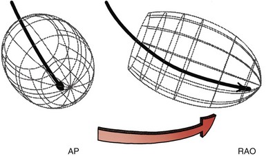
Fluoroscopy is also important for confirmation of the final lead position, whether RVA or some septal location. It is important to rule out inadvertent passage of the lead across a patent foramen ovale and placement in the left ventricle. This can be very deceiving in the anterior projection. A clue is a very high lead takeoff from the right atrium to the apical position. There is often a “chair sign” in which the lead plateaus from the right to the left ventricle. Correct RV apical lead placement versus patent foramen ovale to left ventricular (LV) lead placement can easily be confirmed by use of the RAO and left anterior oblique (LAO) fluoroscopic projections. The RAO projection helps determine how apical the lead is in the right ventricle. The LAO projection will determine whether the lead is in the right or left ventricle. In LAO projection if the lead is in the left ventricle it will be seen going from left to right across the spine. In the lateral projection, RV lead placement is confirmed with the lead tip anterior, whereas if the lead is in the left ventricle, the lead tip will be posterior (see Fig. 21-72).
Right ventricular leads are now being placed on the septum to avoid deleterious hemodynamic effects of the RV apical lead position. Location on the RV septal wall reduces the opportunity for myocardial perforation and diaphragmatic stimulation. RV septal positions result in a more physiologic pattern of ventricular activation. However, it is impossible to distinguish RV free wall (anterior) location from RV septal (posterior) without fluoroscopic confirmation. A new technique has been developed for rapid and consistent lead placement on the right ventricular outflow tract (RVOT) septum.106 The technique uses active-fixation leads and a specially shaped stylet. A generous distal curve is applied to the stylet.107 The distal 2 cm of the stylet is bent to produce a swan neck deformity. The terminal straight end is forward Fig. 21-45, A). If the stylet is placed in reverse, the terminal bend faces posteriorly for easy septal access. Once the lead is place on the septum, final position is confirmed by the PA and 40-degree LAO projections (see Fig. 21-45, B). A high success rate is reported, but the optimal position on the RVOT septum remains to be determined.
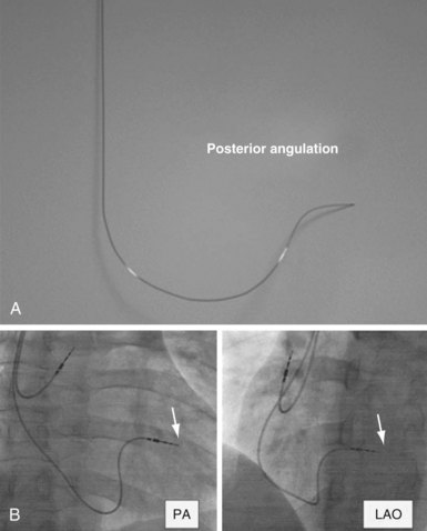
Figure 21-45 Lead placement on right ventricular outflow tract septum.
(From Rosso R, Medi C, Teh AW, et al: Right ventricular septal pacing: the success of stylet-driven active-fixation leads. Pacing Clin Electrophysiol 33:49-53, 2010.)
We recommend that the electrode be passed initially across the tricuspid valve and then out into the pulmonary artery (Fig. 21-46, A to C). This maneuver confirms passage into the right side of the heart and precludes erroneous placement in the coronary sinus (CS). The RAO projection is also helpful in making certain the lead is not in the CS. If the lead is appropriately placed in the RV apex, there will be no posterior component in the course of the lead on the RAO projection. If the lead is in the CS, it will have a posterior course on this projection. If it courses down the middle cardiac vein, the lead will have a posterior course as it traverses the CS, then an anterior course as it traverses this branch.
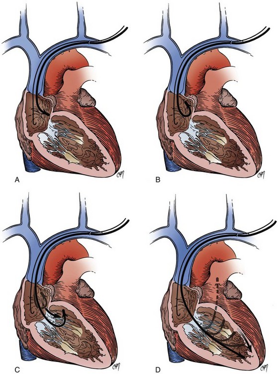
Techniques for placement of the electrode into the RV apex involve the combined manipulation of the lead stylet and electrode body. If one chooses to pass the electrode to the pulmonary artery as an indicator of being across the tricuspid valve, the next maneuver is to advance the stylet to the tip of the electrode. With the stylet advanced to the electrode tip and the electrode tip in the pulmonary artery, the electrode is slowly withdrawn from the pulmonary artery, dragging the tip down along the interventricular septum. This may result in premature ventricular contractions or runs of nonsustained ventricular tachycardia. When the electrode tip has reached the lower third of the septum, the stylet may be retracted about 2 to 3 cm, making the tip floppy; this can be done with a curved or straight stylet (Fig. 21-46, D). The lead tip can be observed to move up and down with the flow of blood, the motion of the tricuspid valve, and RV contractions. As it does so, it will intermittently point toward the RV apex. If one coordinates advancing the lead body (with or without the stylet fully inserted, although generally only straight stylets should be fully inserted at this point) with the appropriate lead trajectory, one can gently seat the tip in the RV apex. This maneuver can be repeated by withdrawal and readvance of the electrode until the desired fluoroscopic location is achieved for threshold testing.
Although the means of venous access has little bearing on electrode placement, there is some difference between the left and right sides. Placement of the ventricular electrode after venous access has been achieved from the left side generally appears to be more expeditious. The ventricular lead with a curved stylet in place will track in a gentle curve from the point of venous entry through to the SVC, right atrium (RA), right ventricle (RV), and pulmonary outflow tract (see Fig. 21-16, A). Typically, little or no difficulty is encountered. There are generally no acute bends or angles. The only occasional impediment is the tricuspid valve, which can be negotiated with one of several techniques. One may be able to advance the tip across the valve without hang-up. If the lead tends to hang up on the valve, retracting the stylet and using the floppy-tip technique already described frequently solves this impasse. In another technique, the curved tip of the electrode is pushed across the valve by creating a loop. Whatever technique is used, because of the anatomic configuration, passage from the left typically presents minimal difficulty. The elderly patient with an extremely tortuous left subclavian–innominate venous system is an exception; the venous structure may have one or more sharp angles or bends in the superior mediastinum before entry into the RA. It would be a truly extreme case for such tortuosity to preclude passage of the electrode from the left.
Passage and placement of the ventricular electrode after right venous access may be much more challenging. Intrinsic to this approach is one acute angle or bend in the venous system (see Fig. 21-16, B). This bend occurs at the junction of the right subclavian vein and internal jugular vein, where the innominate vein is formed. More importantly, this bend is clockwise; therefore, when a lead with a curved stylet is placed in the vein from the right, the electrode is typically directed clockwise or to the lateral RA wall (Fig. 21-47, A). In this situation, routing the tip across the tricuspid valve, which is in the other direction, requires skill and ingenuity. One method involves building a loop in the RA in an attempt to prolapse the lead and to back the electrode across the valve, with the tip ultimately flipping into the right ventricle (Fig. 21-47, B). If the lead has tines, they may be caught on the tricuspid valve and may prevent transit to the right ventricle. Another, somewhat more successful method of crossing the tricuspid valve is the floppy-tip technique. If the curved stylet is withdrawn to the high RA, with the lead tip in the lower RA, the lead will no longer point to the lateral atrial wall. Its trajectory may now be medial, toward the tricuspid valve. Advancing the body of the lead, even though the tip is floppy, allows the lead tip to cross the tricuspid valve into the right ventricle. With this approach, it is important to avoid extreme stylet curves, which increases the tendency of the lead tip to move toward the lateral RA wall. Future lead designs need to incorporate some steering mechanism in either the stylet or the lead.
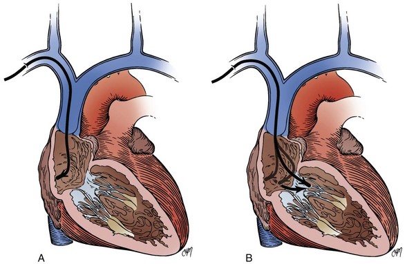
When the implanting physician is satisfied with electrode placement, the stylet may be withdrawn to the vicinity of the lower RA108 (Fig. 21-48). Alternatively, the stylet can be completely removed. Threshold testing is then carried out. If thresholds are acceptable, the ventricular electrode may be secured. Some implanters leave the stylet in the lead with the tip in the lower RA and secure the lead with the anchoring sleeve. This practice reduces the risk for ventricular lead dislodgement during placement and positioning of the atrial lead. Other implanters remove the stylet completely for testing and securing the lead, but not for atrial lead placement and positioning, because there is general agreement that the stylet helps stabilize the ventricular lead during atrial lead manipulation, which otherwise can frequently dislodge the ventricular lead.
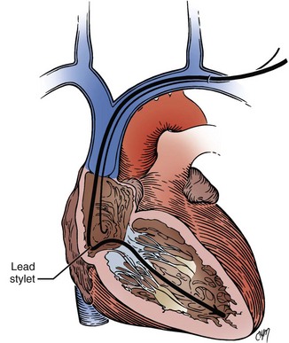
The suture sleeve is advanced down the shaft of the lead body to the vicinity of venous entry. One to three ligatures are applied around the suture sleeve and lead, incorporating a generous amount of pectoral muscle (Fig. 21-49). In our experience, multiple ligatures that are not excessively tight make lead slippage as well as lead damage less likely than a single, tightly applied ligature. Securing the ventricular electrode immediately after satisfactory positioning is important. Early securing helps prevent inadvertent dislodgement whether or not an atrial electrode is to be placed. The ventricular electrode should be oriented somewhat horizontally in a plane roughly parallel to the clavicle. This orientation avoids excessive bending of the lead at the point where it exits the vein.
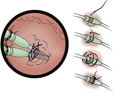
Placement of Atrial Electrodes
Two fundamental techniques relate directly to lead design. The first is placement of an electrode with a preformed curve or atrial J electrode.109 This electrode can have either active-fixation or passive-fixation mechanisms. More often, a lead with passive-fixation tines is used. After insertion into the venous system, the lead tip is positioned with a straight stylet fully inserted in the middle to lower RA. The preformed J has been straightened with the straight stylet. Fluoroscopy can be applied in either the PA or the RAO projection. Under fluoroscopic observation, the straight stylet is withdrawn several centimeters. The atrial lead tip can be observed to begin assuming its J configuration, with the tip beginning to point upward. The lead body is then slowly advanced at the venous entry site (Fig. 21-50). On fluoroscopy, the lead tip is observed to continue its upward motion, eventually seating in the atrial appendage. If the lead tip is too low in the RA, it may catch on or cross the tricuspid valve as the stylet is withdrawn. In this case, the lead is simply withdrawn slightly and the maneuver repeated slightly higher in the RA. If the lead tip is too high in the RA or is in the SVC, the tip will not move upward adequately. In this case, the electrode is repositioned more inferiorly. After gaining experience with this maneuver, one can use it repeatedly and deftly perform the act of retracting the stylet slightly. This brisk move “snaps” the lead tip into the atrial appendage, at times resulting in better electrode-endocardium contact. Frustration and failure may occur if one attempts atrial placement by briskly removing the entire stylet and expecting the electrode to jump into the atrial appendage. This maneuver usually results in the electrode coiling on itself in the SVC or RA. With the stylet so coiled, further attempts at positioning are impossible until it has been reinserted and the process restarted.
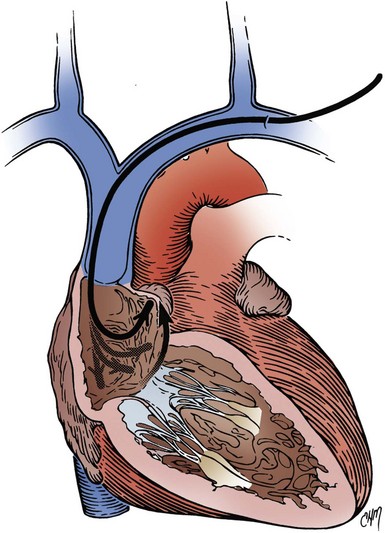
Good atrial positioning consists of a generous J loop, with the tip moving from medial to lateral in a to-and-fro manner in the PA radiographic projection110,111 (Fig. 21-51). In the lateral projection, the tip should be anterior and observed to “bob” up and down. With the firmly seated tip in the atrial appendage, the lead body should be twisted or torqued to the left and right to establish a position of neutral torque. Sometimes, in the process of positioning, torque can build up. If it is not released, electrode dislodgement could result. This same maneuver of twisting can also result in better electrode-myocardium contact. With experience, one gains a sense of the proper J or loop size, which can be a source of frustration. Too much or too little loop can result in dislodgement, depending somewhat on the lead model. Another frustrating event can occur in relation to conformational changes in the vasculature with postural movement. With the patient supine, just the right loop appears to have been created, but as soon as the patient is upright, the conformational change occurs, and the mediastinal vasculature appears to shift inferiorly, pulling up on the lead and obliterating the loop. Unfortunately, this situation may not be discovered until the postimplantation chest radiograph is reviewed. Attempts at gauging the loop size by having the patient take deep inspirations are frequently unrewarding. As a general rule, it is better to create a more generous loop.
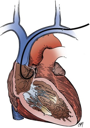
The second fundamental technique of atrial electrode placement involves the use of a straight or non-preformed lead. This lead is positioned in the atrium using a stylet preformed into a J shape that can be modified to other configurations. The stylets typically come with the lead already preformed into the J shape, or if desired, a straight stylet can be shaped into the J or other configurations using the same technique described for curving the ventricular lead stylet. The stylet can then be positioned in the atrium, frequently in the atrial appendage, although it has become increasingly evident that other locations in the atrium, especially the anterior and lateral free walls, can be easily and safely targeted.112 Manipulation of the stylet is required to gain access to the various atrial locations. At times, modification of the preformed stylet shape is required. At the University of Oklahoma (DWR), the modification of the J stylet into a shape similar to that of an Amplatz coronary artery catheter (several varieties) has been helpful in gaining access to a number of positions in the RA. The principal advantage of the non-preformed leads (which use stylets of various shapes) with active-fixation mechanisms is that one is not restricted to the atrial appendage, as discussed later. With a straight or non-preformed active-fixation lead, either a fixed screw or an extendable-retractable screw can be used.
Proper or adequate placement of active-fixation leads is reflected by good electrical threshold measurements. Adequate active lead fixation has been related to a current of injury. Development of a current of injury indicates that within 10 minutes of fixation, pacing thresholds return to acceptable limits and indicate good fixation.113 As discussed in the section on ventricular electrode placement, opinions differ about whether, in addition to the achievement of optimal electrical parameters, a gentle tug on the lead after fixation is helpful in determining whether good mechanical fixation is achieved. Although some implanters use a floppy-tip technique for unusual or precise lead placement, some types of active-fixation leads (especially of the extendable-retractable variety) require full insertion of the stylet to activate the screw-in mechanism. The floppy-tip approach is not effective in this situation. This problem is not encountered with the fixed screw and some of the extendable-retractable screws.
Upgrading Techniques
The upgrade procedure requires new venous access for the introduction of one or more new leads. It may also involve the introduction of a new ventricular lead because of problems with the existing lead. Most pacemaker system upgrades require the replacement of the pulse generator, although occasionally, the existing pulse generator used in the ventricle can be used for atrial pacing. Upgrade procedures usually involve a conventional approach using one of the previously described percutaneous techniques or a venous cutdown. If the first ventricular lead was placed through the cephalic vein, the percutaneous approach is almost mandatory for the upgrade. Conversely, in patients treated with an initial percutaneous subclavian approach, the new lead can be introduced either by cutdown of the cephalic vein or through percutaneous venous access. In the case of an initial percutaneous approach, the ventricular electrode can serve as a map. Using fluoroscopy, one can use the existing ventricular lead as a target to guide the percutaneous needle. Care should be taken not to touch or damage the first lead with the needle. The lead should be used as a reference landmark for the expected location of the subclavian vein. Bognolo et al.114,115 have described a technique to reestablish venous access using the original ventricular lead. The patency of the venous structures can be assessed as previously described with the injection of radiographic contrast material.91
If access to the subclavian vein cannot be obtained by following the axioms of the safe introducer technique previously described by Byrd,76 an extrathoracic puncture of the axillary vein can be done. The puncture of the vein can be expedited with a simple technique: a guidewire or catheter is passed to the vicinity of the subclavian vein through a vein in the arm. The guidewire or catheter can be palpated or viewed fluoroscopically, thus serving as a reference for venous access. In the case of a cutdown on a previously unused cephalic vein, the Ong-Barold percutaneous sheath set technique can be used.99
Occasionally, ipsilateral venous access is impossible. Either the vessel is thrombosed, or some form of obstruction precludes the placement of a second (atrial) lead from the same side. In this case, contralateral venous access can be achieved, and the lead tunneled back to the original pocket (Fig. 21-52). Early injection of radiographic contrast material may expedite the decision to use this approach. The use of the contralateral subclavian (rather than cephalic) vein is recommended for this approach.116 The distance to the original pocket is less, and the new lead is not as susceptible to dislodgement. The same percutaneous techniques and precautions are used as previously described for the percutaneous approach. The only difference is the size of the skin incision, which is limited to about 1 to 1.5 cm. The incision need only be large enough to allow anchoring of the lead and securing of the suture sleeve. As in an initial implantation, the incision should be carried down to the pectoral fascia. Once the lead has been positioned and secured, it can be tunneled to the original pocket.
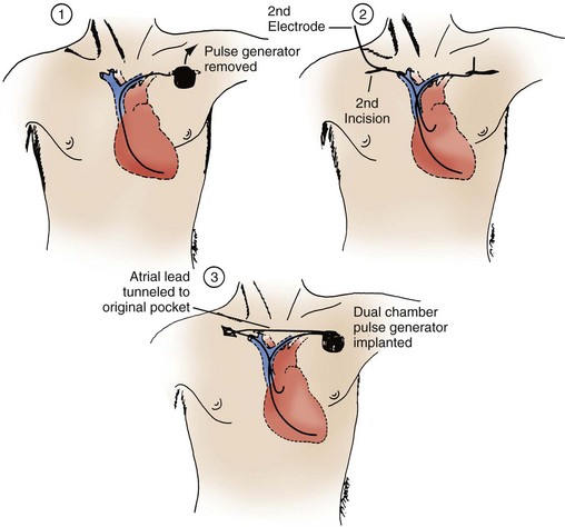
Figure 21-52 Pacemaker upgrade using the contralateral subclavian vein.
(From Belott PH: Use of the contralateral subclavian vein for placement of atrial electrodes in chronically VVI paced patients. Pacing Clin Electrophysiol 6: 781, 1983.)
A number of techniques are available for tunneling. They differ in level of trauma to the tissue and lead. As a rule, the least traumatic technique is desirable. A popular technique is to place the proximal end of the lead or leads to be tunneled in a 14-inch Penrose drain (Fig. 21-53, A). A gentle, nonconstricting tie is applied around the drain just distal to the lead connector (see Fig. 21-52, B). The track of the tunnel, from the satellite wound to the pocket, is infiltrated with local anesthesia by means of an 18-gauge spinal needle. The free end of the Penrose drain is then brought to the receiving wound from the satellite wound in the subcutaneous tissue. This can be accomplished with several techniques. The first technique involves the use of a Kelly clamp or uterine packing forceps. The tip of the clamp is pushed bluntly in the subcutaneous tissue from the receiving wound directly to the satellite wound. Care is taken to keep the tunnel as deep as possible, usually on the surface of the muscle. The free end of the Penrose drain is grasped and pulled back from the satellite wound to the receiving wound. The remainder of the Penrose drain containing the electrode connector pin is pulled through the track to the receiving wound. The tie is released, and the Penrose drain is removed.
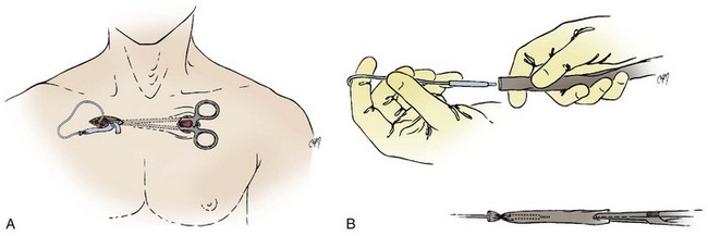
Recently, venoplasty has been introduced as an alternative approach to venous access in situations of subtotal or total venous obstruction. This alternate approach is intended to avoid tunneling techniques or lead extraction as a means of gaining repeat venous access. The tools and techniques of venoplasty are described in Chapter 22.