CHAPTER 6 Peripheral nerve block materials
Nerve stimulators
In 1911, Stoffel demonstrated how a galvanic current could be applied to identify nerve fibers.1 A year later, Perthes described how the use of electrical stimulation could improve the safety of neural block in the practice of anesthesia.2
Nerve stimulation is a popular technique for the location and identification of nerve fibers, particularly in Europe.3 It was introduced into contemporary practice in 1973 by Montgomery and Raj against considerable opposition, particularly in the USA, where many practitioners advocated the dictum ‘no paresthesia, no anesthesia’.4,5 Nerve stimulation, through the intentional avoidance of direct contact with the nerve fiber, aims to reduce the risk of neurologic complications. However, the relations between stimulating current, motor and sensory responses, success rates, and needle–nerve distances are far from clear in the clinical setting.6–8 The nerve stimulation method produces peripheral nerve injury in up to three cases in 10 000.9 In contrast, the transarterial approach to brachial plexus anesthesia produces nerve lesions in 0.8% of cases and the paresthesia approach in 2.8%.10,11 The following is a discussion on the theoretical as well as practical aspects of nerve stimulation and the equipment commonly used to locate nerves. The reader should remain cognizant of the fact that no definitive study outlining the exact nature of the relationship between the stimulating current and the observed responses in clinical practice exists to date.
Electrophysiology
The electrochemical nature of nerve fiber conduction renders it amenable to electrical stimulation. The strength–duration curve demonstrates the relation between the intensity and duration of current in peripheral nerve stimulation (Fig. 6.1).
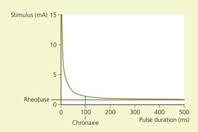
The chronaxie of a motor nerve is less than that of a sensory nerve. In the clinical setting, therefore, a motor response may be elicited without stimulating pain fibers if the duration of impulse is short. Sensory nerves may also be identified using a nerve stimulator if the pulse duration is greater than 400 µs (Table 6.1).
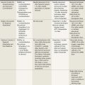
| Nerve fiber type | Chronaxie | |
|---|---|---|
| Cat sural nerve | Aα | 50–100 µs13 |
| Aδ | 170 µs14 | |
| Cat saphenous nerve | C | 400 µs15 |
(From Pither C, Prithvi R, Ford D. The use of peripheral nerve stimulators for regional anesthesia. A review of experimental characteristics, techniques and clinical applications. Reg Anesth 1985; 10; 49–58, with permission from the American Society of Regional Anesthesia and Pain Medicine.)

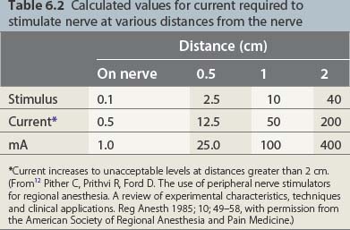
governs the relation between the stimulus intensity and the distance from the nerve. E is the current required, K a constant, Q the minimal current, and r the distance. The significance lies in the squaring of the distance. While one may thus approach the nerve through the progressive diminution of current, at distances greater than 0.5 cm from the nerve large currents are required; at greater than 2 cm, currents of up to 50 mA may be generated. These currents produce pain locally and require that appropriate care be taken in patients with intracardiac electrodes (Table 6.2).
Table 6.2 Calculated values for current required to stimulate nerve at various distances from the nerve

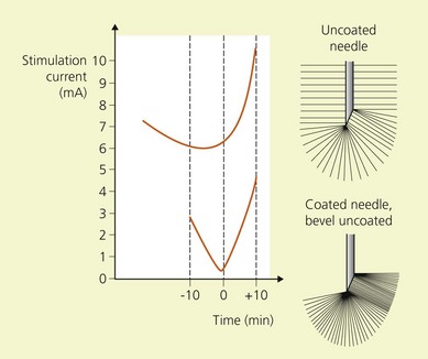
In practice, U corresponds to the potential difference between the poles of the nerve stimulator; R corresponds to the internal resistance of the patient and the resistance of the cables. The negative electrode is connected to the needle and the positive to the patient’s skin via a gel electrode. Because the interior of a nerve at rest is negatively charged relative to the exterior, if the poles are reversed hyperpolarization of the nerve occurs; it is then necessary to apply a current of greater intensity to achieve the same motor response. These currents may be uncomfortable for the patient (Fig. 6.2, Table 6.3).
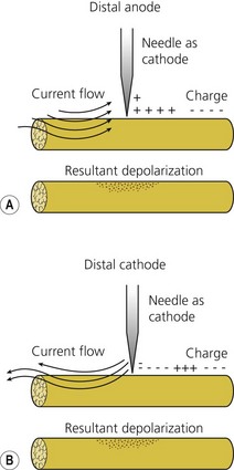
Table 6.3 Polarity of stimulation
| Anodal vs cathodal current required to stimulate peripheral nerve | Reference |
|---|---|
| ∞ 4.57 | BeMent & Ranck, 196916 |
| ∞ 4.3 | Ford et al, 198417 |
(From12 Pither C, Prithvi R, Ford D. The use of peripheral nerve stimulators for regional anesthesia. A review of experimental characteristics, techniques and clinical applications. Reg Anesth 1985; 10; 49–58, with permission from the American Society of Regional Anesthesia and Pain Medicine.)
Characteristics
The characteristics considered desirable in a nerve stimulator are constant current output; digital display; square-shaped, monophasic, negative impulse; variable output control; linear output; clearly marked polarity; short pulse width; variable stimulation frequency of 1 or 2 Hz; high-quality cables and connections; and indicators of power failure, circuit closure, high circuit resistance, and device malfunction.17,18
A digital display of the current intensity delivered is important as one approaches the nerve with very small currents. Knowledge of the precise intensity is vital for accurate nerve location. A final current intensity of 0.5 mA or less is associated with a high success rate in brachial plexus anesthesia.19
To be able to choose between several pulse widths is equally of value. A short pulse width of 50–100 µs is necessary because this corresponds to the chronaxies of mammalian Aα fibers (see Table 6.1). According to Coulomb’s law, the electrical field produced for a current intensity of constant duration is inversely proportional to the square of the distance:
(see previous section, Electrophysiology). Therefore one may bring the needle tip closer to the nerve through the progressive diminution of current intensity. Conversely, as one moves away from the nerve, currents of high intensity are required to stimulate the nerve.
Needles used in peripheral nerve block
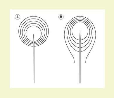
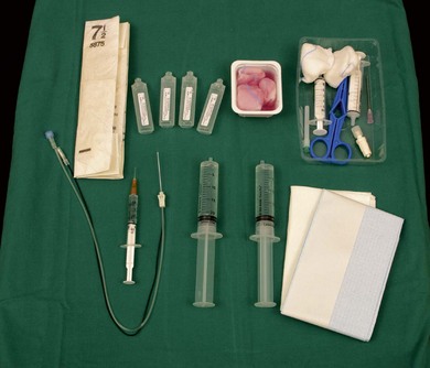
Insulated needles have high precision in locating nerves. The stimulating current is concentrated in, directed from, and forms a sphere around the needle tip. This is more likely to result in accurate delivery of local anesthetic solution. These needles are relatively expensive and skin puncture tends to be more difficult and uncomfortable for the patient. This group of needles may be further subdivided into those with a coated or an uncoated bevel. Needles with a coated bevel have the stimulating current more densely concentrated at the needle tip, resulting in more precision and the requirement for less current to stimulate the nerve (Figs 6.3 and 6.4).20,21 Figure 6.5 illustrates the basic materials required for the performance of a peripheral nerve block.
Peripheral nerve catheters
The first use of peripheral nerve catheters in the management of acute and chronic pain was described in 1946.22 Initially, ureteral lacquered silk catheters were used. Developments in material technology have now provided us with nylon, polyurethane, and Teflon catheters of high quality. These modern catheters are packaged with an appropriately sized stimulating short bevel or Tuohy needle. For example, an 18-G needle will accompany a 20-G catheter.
Catheters used for continuous peripheral nerve block need to be relatively stiff and blunt. This is in contrast to those used for neuraxial block, which need to be pliable and resistant to kinking and knotting. While nylon catheters may be degraded by phenol and ethanol, this problem does not occur with Teflon catheters. Fortunately, local anesthetics appear to have no such degrading effects.23
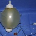
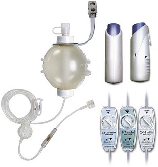
Catheters capable of nerve stimulation have been marketed.24 These devices may result in higher success rates in catheter placement; as with the current systems of advancing the catheter through or over the block needle, the relation between final catheter tip position and the stimulating needle tip position is often far from clear. A variety of cost-effective devices are available that allow continuous infusions of local anesthetic agents. Those with a patient-controlled bolus facility and variable flow rate selectors, such as in Fig. 6.6 allow great flexibility.
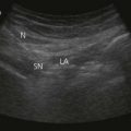
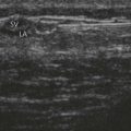
Ultrasound in the practice of regional anesthesia
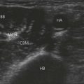
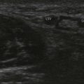
The first report on the use of ultrasound as an aid to nerve location appeared in the anesthesiology literature in 1978.25 Since the mid 1990s, such reports have become more common as the standard of equipment has improved, costs have decreased, and more portable equipment has become available. Ultrasound has been used as an aid in the performance of blocks of the celiac plexus, psoas compartment, stellate ganglion, and others. However, it is in brachial plexus anesthesia that interest has concentrated.
Fundamentals of ultrasonography
Sound waves above a frequency of 20 000 Hz are ultrasound. An ultrasound device can convert electrical current into sound waves and sound waves into electrical current. It thus acts as both transmitter and receiver. The velocity of transmission of sound waves in a medium depends on the acoustic impedance of that medium, which in turn depends on the density of the medium. When sound waves reach two materials of different acoustic impedance, they are reflected back to different degrees. The greater the impedance, the greater the reflectivity of this signal and the brighter the image seen on the screen. In contrast, fluids transmit sound perfectly and so generate no echoes.26
Clinical application
In regional anesthesia, ultrasound has been variously used to identify and mark the skin over blood vessels, to guide the needle or catheter to the nerve, to avoid vital structures, to visualize the spread of local anesthetics, and to validate currently used landmarks.27
Despite confirmation of correct needle and catheter position with ultrasound, a 100% clinical success rate is not guaranteed. Nevertheless, the reported success rates are similar to those with other techniques.25 Furthermore, the loss of resolution at greater depths renders the technology less accurate for blocks such as that of the psoas compartment. Devices with the lower frequency of 3.5–5 MHz are required to penetrate these depths.
The value of this technology has been demonstrated in avoiding pneumothorax in infraclavicular blocks by allowing one to visualize the position of the needle tip in relation to vital structures.28,29 It has led to recommendations for the modification of some approaches depending on patient size, obesity, and sex.30 It may permit the use of smaller anesthetic volumes and result in a higher success rate and the speedier performance of some blocks.31
1 Stoffel A. Eine neue Operation für spastische Lähmungen. Münch Med Woch. 1911;47:2493-2498.
2 Perthes G. Ueber Leitunganästhesie unter zuhilfenahme elektrischer reizung. Münch Med Woch. 1912;47:2545-2548.
3 Benhamou D. Axillary plexus block using multiple nerve stimulation: a European view. Reg Anesth Pain Med. 2001;26:495-498.
4 Montgomery SJ, Raj PP, Nettles D, et al. The use of the nerve stimulator with standard unsheathed needles in nerve blockade. Anesth Analg. 1973;52:827-831.
5 Raj PP. Ancillary measures to ensure success. Reg Anesth. 1980;5:9-12.
6 Gold SJ, Duthie DJR. Nerve stimulator current and regional nerve block efficacy. Br J Anaesth. 2001;86:321.
7 Riegler FX. Brachial plexus block with the nerve stimulator: motor response characteristics at three sites. Reg Anesth. 1992;176:295-299.
8 Urmey WF, Stanton J, O’Brien S, et al. Inability to consistently elicit a motor response following sensory paresthesia during interscalene block administration. Reg Anesth. 1998;23:7-57.
9 Auroy Y, Benhamou D, Bargues L, et al. Major complications of regional anesthesia in France. The SOS regional anesthesia hotline service. Anesthesiology. 2002;97:1274-1279.
10 Plevak D, Linstromberg J, Danielsson D. Paresthesia vs non-paresthesia – the axillary block. Anesthesiology. 1983;59:A216.
11 Selander D, Edshage S, Wolff T. Parasthesiae or no parasthesiae? Nerve lesions after axillary blocks. Acta Anaesth Scand. 1979;23:27-33.
12 Pither C, Prithvi R, Ford D. The use of peripheral nerve stimulators for regional anesthesia. A review of experimental characteristics, technique and clinical applications. Reg Anesth. 1985;10:49-58.
13 Shaefer J. Elektrophysiologie I. Wein: Franz Deufficke; 1940.
14 Casey K. Which elements are excited in electrical stimulation of mammalian central nervous system: a review. Brain Res. 1975;98:417-440.
15 Koslow M, Bak A, Li C. C fibre excitability in the cat. Exp Neurol. 1973;41:745-753.
16 BeMent SL, Ranck JB. A quantitative study of electrical stimulation of central myelinated fibers. Expo Neurol. 1969;24:147-170.
17 Ford D, Pither C, Raj P. Electrical characteristics of peripheral nerve stimulators: implications for nerve localization. Reg Anesth. 1984;9:73-77.
18 Galindo A. Electrical localization of peripheral nerves: instrumentation and clinical experience. Reg Anesth. 1983;8:49-50.
19 De Andres J, Sala-Blanch X. Peripheral nerve stimulation in the practice of brachial plexus anesthesia: a review. Reg Anesth Pain Med. 2001;26:478-483.
20 Bashein G, Haschke RH, Ready LB. Electrical nerve location: numerical and electrophoretic comparison of insulated vs uninsulated needles. Anesth Analg. 1984;63:919-924.
21 . [Anonymous]. Technical aspects of peripheral electrical nerve stimulation. Online. Available http://www.bbraunusa.com/stimuplex/pens1.html
22 Ansboro F. Method of continuous brachial plexus block. Am J Surg. 1946;71:716-722.
23 Gale DW, Ramamurthy S, Valley MA. Commonly used neurolytic solutions significantly degrade nylon but not Teflon epidural catheters. Reg Anesth. 1996;21:S51.
24 Copeland SJ, Laxton MA. A new stimulating catheter for continuous peripheral nerve blocks. Reg Anesth Pain Med. 2001;26:589-590.
25 La Grange P, Foster P, Pretorius L. Application of the Doppler ultrasound blood flow detector in supraclavicular brachial plexus block. Br J Anaesth. 1978;50:965-967.
26 De Andres J, Sala-Blanch X. Ultrasound in the practice of brachial plexus anesthesia. Reg Anesth Pain Med. 2002;27:77-89.
27 Peterson MK, Millar FA, Sheppard DG. Ultrasound-guided nerve blocks [editorial]. Br J Anaesth. 2002;88:621-624.
28 Kapral S, Krafft P, Eisenberger K, et al. Ultrasound-guided supraclavicular approach for regional anesthesia of the brachial plexus. Anesth Analg. 1994;78:507-513.
29 Ootaki C, Hyashi H, Amano M. Ultrasound-guided infraclavicular brachial plexus block: an alternative technique to anatomical landmark-guided approaches. Reg Anesth Pain Med. 2000;25:600-604.
30 Greher M, Retzl G, Niel P, et al. Ultrasonographic assessment of topographic anatomy in volunteers suggests a modification of the infraclavicular vertical plexus block. Br J Anaesth. 2002;88:632-636.
31 Marhofer P, Schrogendorfer K, Koinig H, et al. Ultrasonographic guidance improves sensory block and onset time of three-in-one blocks. Anesth Analg. 1997;85:854-857.