Periapical radiography
Main indications
The main clinical indications for periapical radiography include:
• Detection of apical infection/inflammation
• Assessment of the periodontal status
• After trauma to the teeth and associated alveolar bone
• Assessment of the presence and position of unerupted teeth
• Assessment of root morphology before extractions
• Preoperative assessment and postoperative appraisal of apical surgery
• Detailed evaluation of apical cysts and other lesions within the alveolar bone
Ideal positioning requirements
The ideal requirements for the position of the image receptor (film packet or digital sensor) and the X-ray beam, relative to a tooth, are shown in Fig. 9.1. They include:
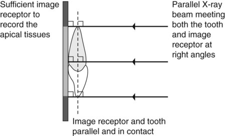
• The tooth under investigation and the image receptor should be in contact or, if not feasible, as close together as possible.
• The tooth and the image receptor should be parallel to one another.
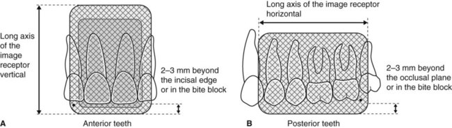
• The image receptor should be positioned with its long axis vertically for incisors and canines, and horizontally for premolars and molars with sufficient receptor beyond the apices to record the apical tissues.
• The X-ray tubehead should be positioned so that the beam meets the tooth and the image receptor at right angles in both the vertical and the horizontal planes.
Radiographic techniques
Paralleling technique
Theory
1. The image receptor is placed in a holder and positioned in the mouth parallel to the long axis of the tooth under investigation.
2. The X-ray tubehead is then aimed at right angles (vertically and horizontally) to both the tooth and the image receptor.
3. By using a film/sensor holder with fixed image receptor and X-ray tubehead positions, the technique is reproducible.
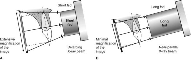
This positioning has the potential to satisfy four of the five ideal requirements mentioned earlier. However, the anatomy of the palate and the shape of the arches mean that the tooth and the image receptor cannot be both parallel and in contact. As shown in Fig. 9.2, the image receptor has to be positioned some distance from the tooth.
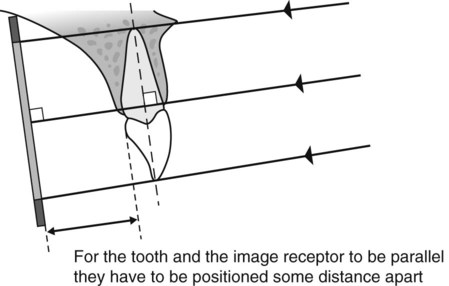
To prevent the magnification of the image that this separation would cause, an X-ray beam as non-divergent as possible is required (see Fig. 9.3). As explained in Chapter 5, this is achieved by having a long focal spot to skin distance (fsd), ideally of 200 mm.
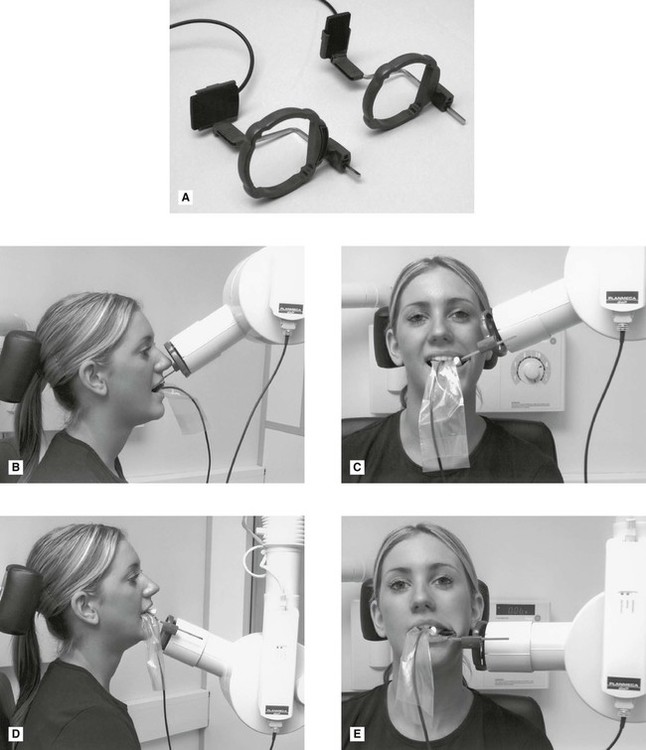
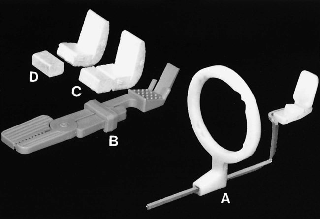
Film packet/sensor holders
A variety of holders has been developed for this technique. The different holders vary in cost and design, but essentially consist of three basic components (as shown in Fig. 9.4):
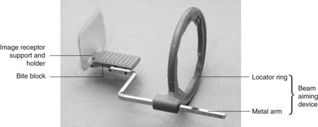
• A mechanism for holding the image receptor parallel to the teeth that also prevents bending of the receptor
• An X-ray beam-aiming device. This may or may not provide additional collimation of the beam.
The different components of the various holders usually need to be assembled together before the holder can be used clinically. The holder design used depends upon whether the tooth under investigation is:
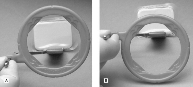
These variables mean that assembling the holder can be confusing, but it must be done correctly. To facilitate this assembly some manufacturers now colour-code the various components. Once assembled correctly the entire image receptor should be visible when viewed through the beam-aiming device, as shown in Fig. 9.5.
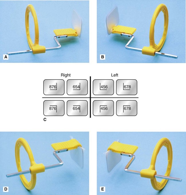
The choice of holder is a matter of personal preference and dependent upon the type of image receptor – film packet or digital sensor (solid-state or phosphor plate) – being used. A selection of different holders is shown in Fig. 9.6.

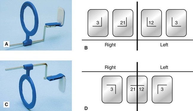
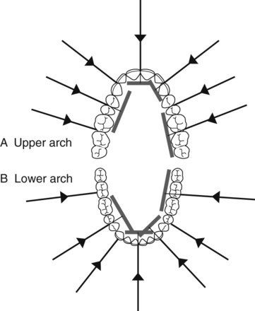
Typically, the same anterior holder can be used for right and left maxillary and mandibular incisors and canines utilizing a small image receptor (22 × 35 mm) with its long axis vertical. Four images in the maxilla and three images in the mandible are usually required to cover the right and left incisors and canines, as shown in Fig. 9.7.
Typically different holders are required for the right and left premolar and molar maxillary and mandibular posterior teeth. The different designs allow the holders to hook around the cheek and corner of the mouth. A large image receptor (31 × 41 mm) is ideally utilized with its long axis horizontal. Two images are usually required to cover the premolar and molar teeth in each quadrant, as shown is Fig. 9.8.
Positioning techniques
The radiographic techniques for the permanent dentition can be summarized as follows:
1. The patient is positioned with the head supported and with the occlusal plane horizontal.
2. The holder and image receptor are placed in the mouth as follows:
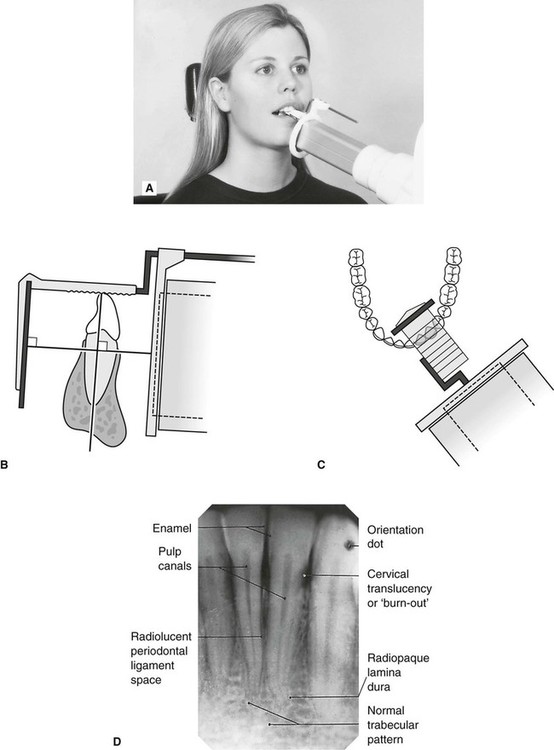
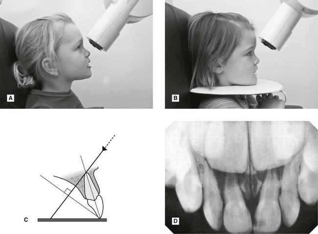
a. Maxillary incisors and canines – the image receptor is positioned sufficiently posteriorly to enable its height to be accommodated in the vault of the palate
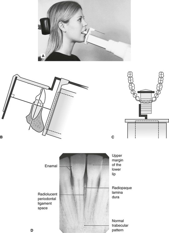
b. Mandibular incisors and canines – the image receptor is positioned in the floor of the mouth, approximately in line with the lower canines or first premolars
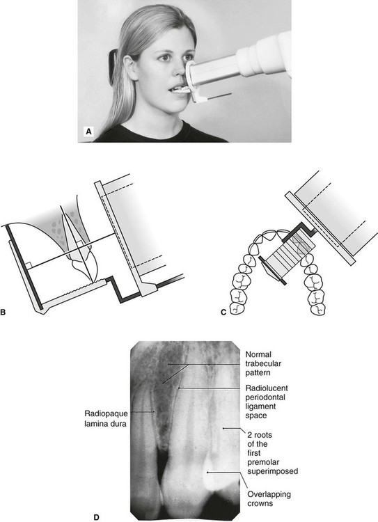
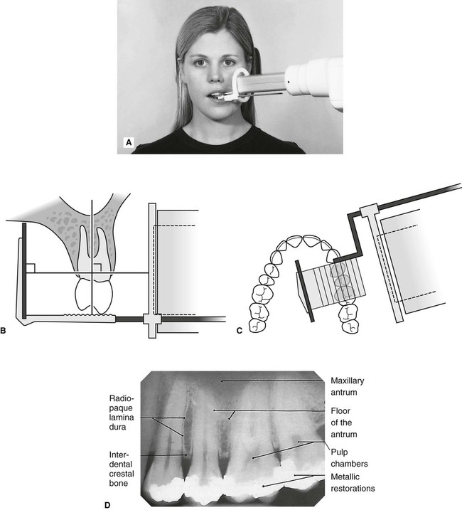
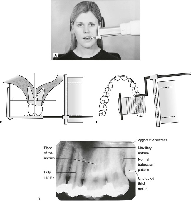
c. Maxillary premolars and molars – the image receptor is placed in the midline of the palate, again to accommodate its height in the vault of the palate
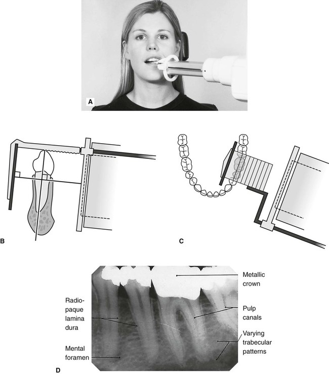
d. Mandibular premolars and molars – the image receptor is placed in the lingual sulcus next to the appropriate teeth.
3. The holder is rotated so that the teeth under investigation are touching the bite block.
4. A cottonwool roll is placed on the reverse side of the bite block. This often helps to keep the tooth and image receptor parallel and may make the holder less uncomfortable.
5. The patient is requested to bite gently together, to stabilize the holder in position.
6. The locator ring is moved down the indicator rod until it is just in contact with the patient’s face. This ensures the correct focal spot to film distance (fsd).
7. The spacer cone is aligned with the locator ring. This automatically sets the vertical and horizontal angles and centres the X-ray beam on the image receptor
Positioning clinically using film packets and digital phosphor plates is shown in Figs 9.9–9.16 for the following different areas of the mouth:
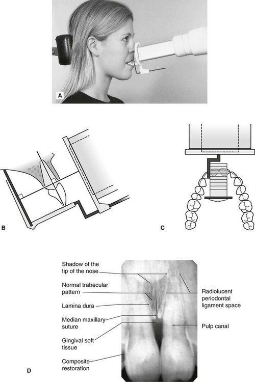
Maxillary central incisor (Fig. 9.9)
Maxillary premolars (Fig. 9.11)
Mandibular incisors (Fig. 9.13)
1. Full mouth survey is the terminology used to describe the full collection of 15 periapical radiographs (seven anterior and eight posterior) showing the full dentition.
2. When using film packets and digital phosphor plates the end of the receptor with the orientation dot should be placed opposite the crowns of the teeth to avoid subsequent superimposition of the dot over an apex.
Positioning using solid-state digital sensors
Clinical positioning of holders for the paralleling technique when using solid-state digital sensors can be more difficult because of the bulk and absolute rigidity of the sensor. Those systems employing cables also require extra care with regard to the position of the cable to avoid damaging it. Once the holder is inserted into the mouth, the positioning of the tubehead is the same as described previously when using other types of image receptors and is shown in Fig. 9.17 for different parts of the mouth.
Bisected angle technique
Theory
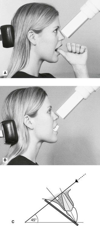
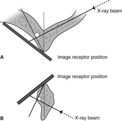
The theoretical basis of the bisected angle technique is shown in Fig. 9.18 and can be summarized as follows:
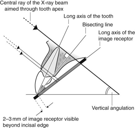
1. The image receptor is placed as close to the tooth under investigation as possible without bending the packet.
2. The angle formed between the long axis of the tooth and the long axis of the image receptor is assessed and mentally bisected.
3. The X-ray tubehead is positioned at right angles to this bisecting line with the central ray of the X-ray beam aimed through the tooth apex.
4. Using the geometrical principle of similar triangles, the actual length of the tooth in the mouth will be equal to the length of the tooth on the image.
Positioning techniques
Using film packet/digital sensor holders
Various holders are available, a selection of which are shown in Fig. 9.20. The Rinn Bisected Angle Instruments (BAI) closely resemble the paralleling technique holders and consist of the same three basic components – image receptor holding mechanism, bite block and an X-ray beam-aiming device – but the image receptor is not held parallel to the teeth. The more simple holders and the disposable bite blocks hold the image receptor in the desired position but the X-ray tubehead then has to be aligned independently. In summary:
1. The image receptor is pushed securely into the chosen holder. Either a large or small size of image receptor is used so that the particular tooth being examined is in the middle of the receptor, as shown in Fig. 9.21. When using a film packet the white surface faces the X-ray tubehead and the film orientation dot is opposite the crown.
2. The X-ray tubehead is positioned using the beam-aiming device if available OR the operator has to assess the vertical and horizontal angulations by observation and then position the tubehead without a guide.
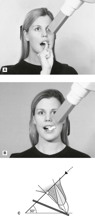
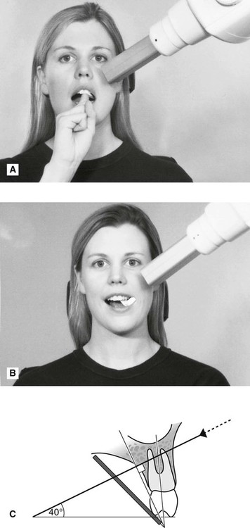
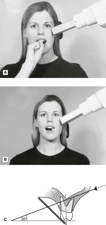
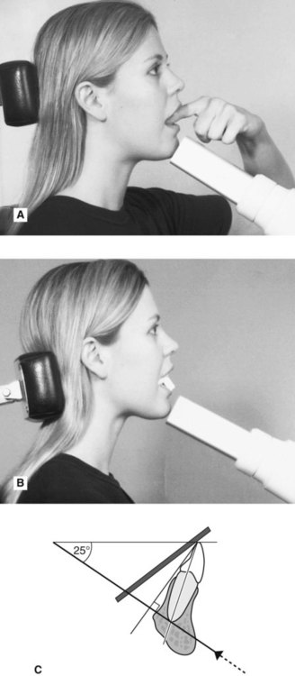
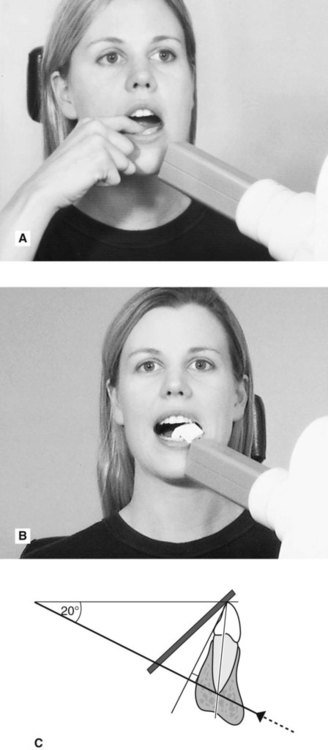
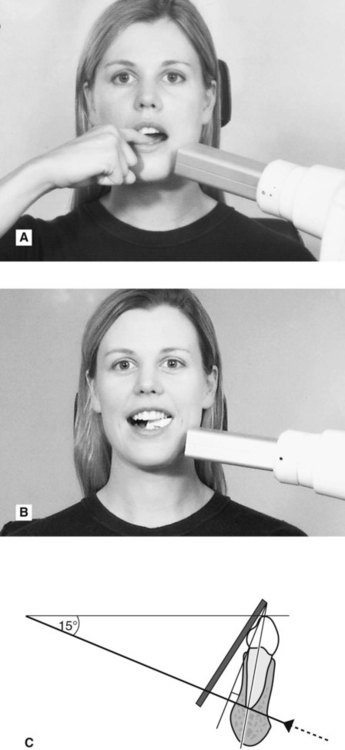
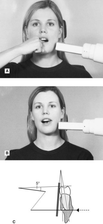
Using the patient’s finger
1. The appropriate sized image receptor is positioned and orientated in the mouth as shown in Fig. 9.18 with about 2 mm extending beyond the incisal or occlusal edges, to ensure that all of the tooth will appear on the image. The patient is then asked to gently support the image receptor using either an index finger or thumb.
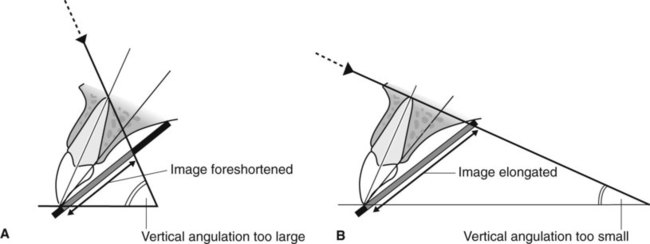
2. The operator then assesses the vertical and horizontal angulations by observation and positions the tubehead without a guide. The effects of incorrect tubehead position are shown in Fig. 9.22.
The specific positioning for different areas of the mouth, using both simple holders and the patient’s finger to support the image receptor, is shown in Figs 9.23–9.30.
Comparison of the paralleling and bisected angle techniques
The advantages and disadvantages of the two techniques can be summarized as follows:
Advantages of the paralleling technique
• Geometrically accurate images are produced with little magnification.
• The shadow of the zygomatic buttress appears above the apices of the molar teeth.
• The periodontal bone levels are well represented.
• The periapical tissues are accurately shown with minimal foreshortening or elongation.
• The crowns of the teeth are well shown enabling the detection of approximal caries.
• The horizontal and vertical angulations of the X-ray tubehead are automatically determined by the positioning devices if placed correctly.
• The X-ray beam is aimed accurately at the centre of the image receptor – all areas of the image receptor are irradiated and there is no coning off or cone cutting.
• Reproducible radiographs are possible at different visits and with different operators.
• The relative positions of the image receptor, teeth and X-ray beam are always maintained, irrespective of the position of the patient’s head. This is useful for some patients with disabilities.
Disadvantages of the paralleling technique
• Positioning of the image receptor can be very uncomfortable for the patient, particularly for posterior teeth, often causing gagging.
• Positioning the holders within the mouth can be difficult for inexperienced operators particularly when using solid-state digital sensors.
• The anatomy of the mouth sometimes makes the technique impossible, e.g. a shallow, flat palate.
• The apices of the teeth can sometimes appear very near the edge of the image.
• Positioning the holders in the lower third molar regions can be very difficult.
• The technique cannot be performed satisfactorily using a short focal spot to skin distance (i.e. a short spacer cone) because of the resultant magnification.
Advantages of the bisected angle technique
• Positioning of the image receptor is reasonably comfortable for the patient in all areas of the mouth.
• Positioning is relatively simple and quick.
• If all angulations are assessed correctly, the image of the tooth will be the same length as the tooth itself and should be adequate (but not ideal) for most diagnostic purposes.
Disadvantages of the bisected angle technique
• The many variables involved in the technique often result in the image being badly distorted.
• Incorrect vertical tube head angulation will result in foreshortening or elongation of the image.
• The periodontal bone levels are poorly shown.
• The shadow of the zygomatic buttress frequently overlies the roots of the upper molars.
• The horizontal and vertical angles have to be assessed by observation for every patient and considerable skill is required.
• It is not possible to obtain reproducible views.
• Coning off or cone cutting may result if the central ray is not aimed at the centre of the image receptor, particularly if using rectangular collimation.
• Incorrect horizontal tube head angulation will result in overlapping of the crowns and roots.
• The crowns of the teeth are often distorted, thus preventing the detection of approximal caries.
• The buccal roots of the maxillary premolars and molars are foreshortened.
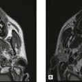
A visual comparison between the two techniques, showing how dramatic the variation in image quality and reproducibility can be, is shown in Figs 9.31 and 9.32.
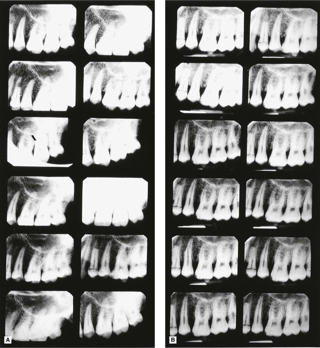
 , on the same phantom head, taken by 12 different experienced operators. The obvious reproducibility and accurate imaging show why the paralleling technique should be regarded as the technique of choice.
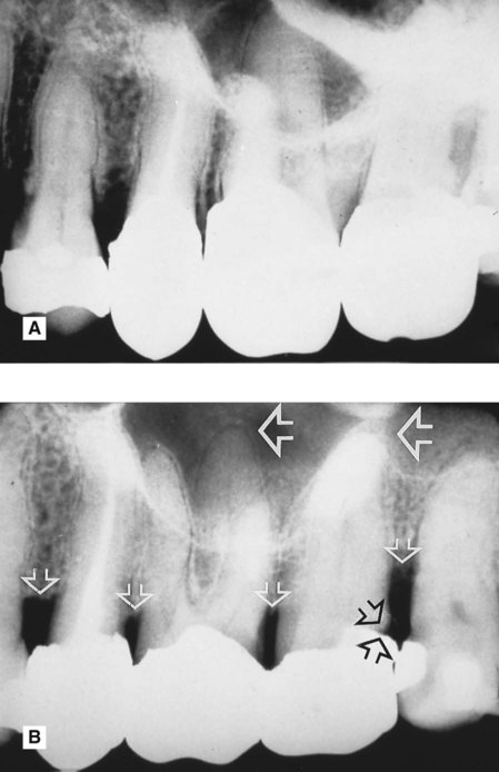
 8 taken on the same patient, by the same operator, on the same day. Note the difference in the periodontal bone levels (small white open arrows), the restoration in
  (black open arrows) and the apical tissues
  (large white open arrows).
Positioning difficulties often encountered in periapical radiography
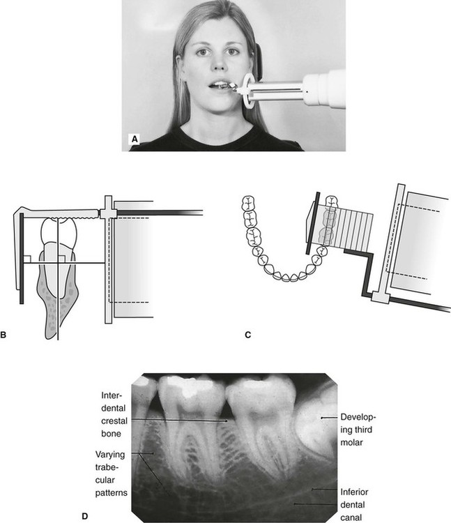
Problems posed by mandibular third molars
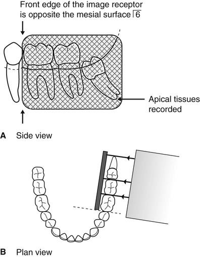
The main difficulty is placement of the image receptor sufficiently posteriorly to record the entire third mandibular molar (particularly when it is horizontally impacted) and the surrounding tissues, including the inferior dental canal (see Fig. 9.33).
Possible solutions
• Using specially designed or adapted holders as shown in Fig. 9.34 to hold and position the image receptor in the mouth, as follows:
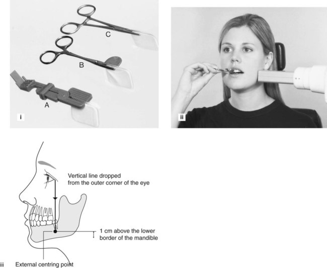
1. The holder is clipped securely on to the top edge of the image receptor.
2. With the patient’s mouth open, the image receptor is positioned gently in the lingual sulcus as far posteriorly as possible.
3. The patient is asked to close the mouth (so relaxing the tissues of the floor of the mouth) and at the same time the image receptor is eased further back into the mouth, if required, until its front edge is opposite the mesial surface of the mandibular first molar.
4. The patient is asked to bite on the holder and to support it in position.
5. The X-ray tubehead is positioned at right angles to the third molar and the image receptor and centred 1 cm up from the lower border of the mandible, on a vertical line dropped from the outer corner of the eye (see Fig. 9.34).
• Taking two radiographs of the third molar using two different horizontal tubehead angulations, as follows:
1. The image receptor is positioned as posteriorly as possible (using the technique described with the holders).
2. The X-ray tubehead is aimed with the ideal horizontal angulation so the X-ray beam passes between the second and third molars. (With horizontally impacted third molars, the apex may not be recorded using this positioning, as shown in Fig. 9.35.)
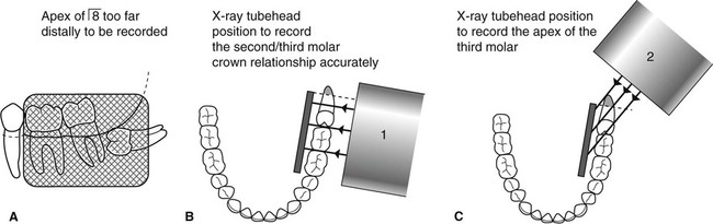
3. A second image receptor is placed in the same position as before, but the X-ray tubehead is positioned further posteriorly aiming forwards to project the apex of the third molar on to the receptor. (With this positioning, the crowns of the second and third molars will be overlapped, as shown in Fig. 9.35.)
Note: The vertical angulation of the X-ray tubehead is the same for both projections.
Problems of gagging
Possible solutions
• Patient sucking a local anaesthetic lozenge before attempting to position the image receptor
• Asking the patient to concentrate on breathing deeply while the image receptor is in the mouth
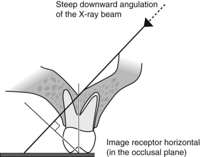
• Placing the image receptor flat in the mouth (in the occlusal plane) so it does not touch the palate, and applying the principles of the bisected angle technique – the long axes of the tooth and image receptor are assessed by observation and the X-ray tubehead’s position modified accordingly, as shown in Fig. 9.36.
Problems encountered during endodontics
The main difficulties involve:
• Image receptor placement and stabilization when endodontic instruments, rubber dam and rubber dam clamps are in position
• Identification and separation of root canals
• Assessing root canal lengths from foreshortened or elongated radiographs.
Possible solutions
• The problem of image receptor placement and stabilization can be solved by:
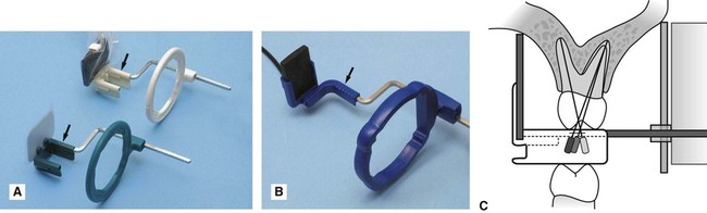
– Using a simple image receptor holder such as the Rinn Eezee-Grip®, as shown in Fig. 9.37. This is positioned in the mouth and then held in place by the patient.
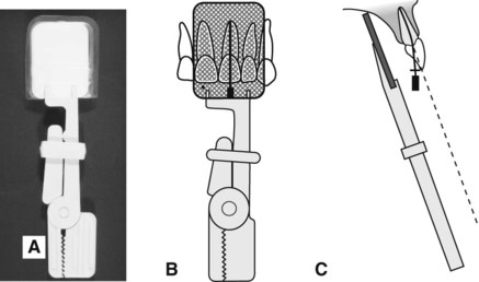
– Using one of the special endodontic image receptor holders that have been developed. These incorporate a modified bite platform area, to accommodate the handles of the endodontic instruments, while still allowing the image receptor and the tooth to be parallel. (See Fig. 9.38.)
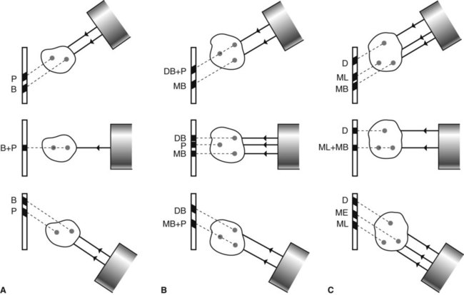
• The problem of identifying and separating the root canals can be solved by taking at least two radiographs, using different horizontal X-ray tubehead positions, as shown in Fig. 9.39.
• The problems of assessing root canal length can be solved by:
– Taking an accurate paralleling technique periapical preoperatively and measuring the lengths of the root(s) directly from the radiograph before beginning the endodontic treatment. The amount of distortion on subsequent films can then be assessed.
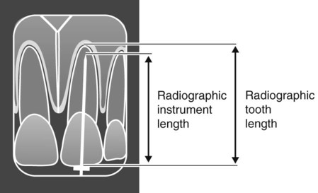
– Calculating mathematically the actual length of a root canal from a distorted bisected angle technique periapical taken with the diagnostic instrument within the root canal at the clinically assessed apical stop.
The calculation is done as follows (see Fig. 9.40):
Problems of the edentulous ridge
Possible solutions
• In edentulous patients, the lack of height in the palate, or loss of lingual sulcus depth, contraindicates the paralleling technique and all periapical radiographs should be taken using a modified bisected angle technique. The long axes of the image receptor and the alveolar ridge are assessed by observation and the X-ray tubehead position adjusted accordingly as shown in Fig. 9.41.
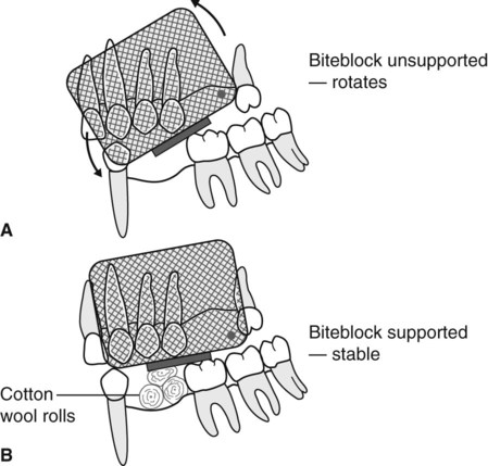
• In partially dentate patients, the paralleling technique can usually be used. If the edentulous area causes the image receptor holder to be displaced, the deficiency can be built up by using cottonwool rolls, as shown in Fig. 9.42.
Assessment of image quality
Assessment of the quality of all radiographic images should be regarded as a routine part of any quality assurance (QA) programme (see Ch. 17). Essentially image quality assessment involves three separate stages, namely:
• Comparison of the image against ideal quality criteria
• Subjective rating of image quality using published standards
• Detailed assessment of rejected films to determine the sources of error.
Ideal quality criteria
• The image should have acceptable definition with no distortion or blurring.
• The image should include the correct anatomical area together with the apices of the tooth/teeth under investigation with at least 3–4 mm of surrounding bone.
• There should be no overlap of the approximal surfaces of the teeth.
• The desired density and contrast for film-captured images will depend on the clinical reasons for taking the radiograph, e.g.
– to assess caries, restorations and the periapical tissues films should be well exposed and show good contrast to allow differentiation between enamel and dentine and between the periodontal ligament space, the lamina dura and trabecular bone.
– to assess the periodontal status films should be underexposed to avoid burnout of the thin alveolar crestal bone. (see Ch. 22)
• The images should be free of coning off or cone-cutting and other film handling errors.
• The images should be comparable with previous periapical images, both geometrically and in density and contrast.
Subjective rating of image quality
A simple three-point subjective rating scale for all intraoral and extraoral film-captured radiographs was published in the UK in 2001 in the Guidance Notes for Dental Practitioners on the Safe Use of X-ray Equipment. A summary is shown in Table 9.1, and is repeated in Chapters 10 and 15. Image quality is discussed in detail, together with the errors associated with exposure factors and chemical processing, in Chapter 19. Patient preparation and positioning errors in periapical radiography are described below.
Table 9.1
| Rating | Quality | Basis |
| 1 | Excellent | No errors of patient preparation, exposure, positioning, processing or film handling |
| 2 | Diagnostically acceptable | Some errors of patient preparation, exposure, positioning, processing or film handling, but which do not detract from the diagnostic utility of the radiograph |
| 3 | Unacceptable | Errors of patient preparation, exposure, positioning, processing or film handling, which render the radiograph diagnostically unacceptable |
Assessment of rejected films and determination of errors
Patient preparation and positioning (radiographic technique) errors (Fig. 9.44)
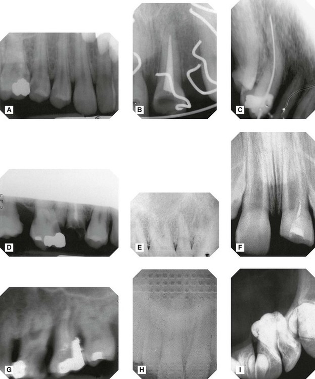
A Image receptor not positioned sufficiently apically to cover the area of interest – apices and periapical tissues not shown.
B Failure to remove an orthodontic appliance.
C Image receptor positioned incorrectly and bent during exposure – image geometrically distorted.
D Failure to align the X-ray tubehead correctly in the vertical plane –coning off of the superior part of the image.
E X-ray tubehead positioned at too steep an angle in the vertical plane – foreshortening and geometrical distortion of the image.
F X-ray tubehead positioned at too shallow an angle in the vertical plane – elongation and geometrical distortion of the image.
G Failure to instruct the patient to remain still – image blurred as a result of movement.
H Image receptor (film packet) incorrectly placed back to front – pattern of the lead foil is evident.
I Image receptor (film packet) inadvertently used twice – double exposure.
• Failure to remove dentures or orthodontic appliances
• Failure to position the image receptor correctly to capture the area of interest, thereby failing to image the apices and periapical tissues
• Failure to position the image receptor correctly causing it to bend (if flexible) creating geometrical distortion
• Failure to orientate the image receptor correctly and using it back-to-front
• Failure to align the X-ray tubehead correctly in the horizontal plane, either
– Too far anteriorly or posteriorly (coning off or cone cutting)
– Not aimed through the contact areas at right angles to the teeth and the image receptor causing overlapping of the contact areas
• Failure to align the X-ray tubehead correctly in the vertical plane, either
– Too far superiorly or inferiorly (coning off or cone cutting)
– Too steep an angle causing foreshortening and geometrical distortion
– Too shallow an angle causing elongation and geometrical distortion
• Failure to instruct the patient to remain still during the exposure with subsequent movement resulting in blurring
Note: Many of these technique errors can be avoided by using the paralleling technique utilizing image receptor holders with beam-aiming devices.
To access the self assessment questions for this chapter please go to www.whaitesessentialsdentalradiography.com