16 Percutaneous Mitral Commissurotomy and Balloon Aortic Valvuloplasty
Percutaneous Mitral Commissurotomy
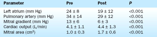
Hemodynamic results have been well characterized by the Inoue Multi-Center Registry. On average there is more than 80% increase in mitral valve area. Balloon inflation results in splitting of the fused commissures with reductions in the transmitral pressure gradient, the mean left atrial pressure, and the pulmonary artery pressure. The cardiac output and mitral valve area increase (Table 16-1).
The most important complication of the procedure is mitral regurgitation. Mitral valve replacement is needed during the initial hospitalization in about 2% of patients. An additional 3% to 4% have resultant 3+ or greater mitral regurgitation without the need for immediate valve replacement. Other complications are shown in Table 16-2.
Table 16-2 Complications of Percutaneous Transvenous Mitral Commissurotomy
| Complication | % |
|---|---|
| Hospital mitral valve replacement (MVR) | 1.0 |
| Hospital death | 1.4 |
| Transient ischemic attack | 0.6 |
| Stroke | 0 |
| Cardiac perforation | 1.4 |
| Pericardiocentesis | 1.0 |
| Myocardial infarction | 0.3 |
| Cardioversion shock for atrial or ventricular fibrillation | <1 |
| Vascular repair | 0.6 |
| Transfusion | 0.3 |
| Temporary pacer | 0 |
| Mitral regurgitation 3+ or more (no MVR) | 3.8 |
| Atrial septal defect >1.5 | 3.1 |
| Failure to cross mitral valve | 1.7 |
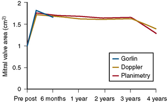
The durability of the results is excellent. Figure 16-1 shows the stability of the achieved valve area over a period of years. The 5-year actuarial freedom from death with mitral valve replacement or repeat balloon commissurotomy for the Inoue Registry population was 71%. More than 80% of the patients remained symptomatically improved at 5 years.
Technique
The Inoue Balloon
The Inoue device differs substantially from conventional balloons. It is constructed of two layers of latex with a nylon mesh sandwiched in between them. The latex is compliant, whereas the nylon mesh limits the maximum inflated diameter of the balloon and gives it a unique shape and three-stage inflation characteristics (Fig. 16-2).
Patient Evaluation
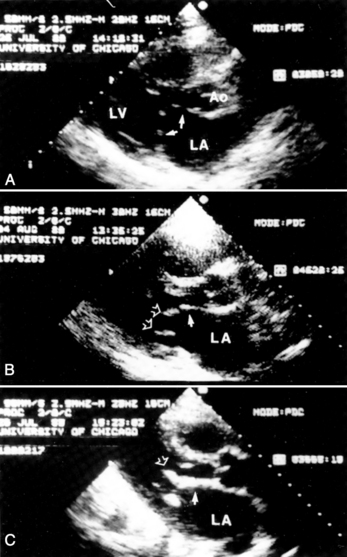
Evaluation by two-dimensional transthoracic and transesophageal echocardiography is essential before mitral valvotomy. Patients with thin, pliable mitral leaflets and minimally diseased subvalvular apparatus have the best long-term outcome from surgical commissurotomy (Fig. 16-3). This is no less true when using percutaneous methods to achieve commissurotomy. Although the immediate results of percutaneous transvenous mitral commissurotomy (PTMC) are acceptable in patients with significant valve deformity, the restenosis rate and the need for rate mitral valve replacement remains higher in these patients. The goal of therapy and the long-term prospects for event-free survival must be appropriate for patients with significant valve deformity and echocardiographic scores greater than 10 to 12.
Cardiac Catheterization Technique
1. The left femoral arterial and venous sheaths are placed. Because a pigtail catheter will be left in place in the left ventricle for a relatively long period of time, we prefer to use 5F or 6F arterial catheters.
2. A multilumen pulmonary artery balloon catheter with thermodilution cardiac output capability is used for right heart catheterization. Left femoral access is preferred for these catheters, leaving the right side for insertion of the dilatation balloon catheter. Pulmonary artery catheters with oximetric monitoring simplify the evaluation of venous saturations for the detection of atrial shunting following the procedure, although these catheters are more difficult to place than are conventional pulmonary artery catheters. Passage of the pulmonary artery catheter is facilitated by the use of an extra-stiff 0.025-inch guidewire.
3. Left ventriculography and coronary arteriography are performed when indicated. The AHA/ACC guidelines for valvular heart disease recommend arteriography for men over age 35 years, or women over age 35 years who also have risk factors.
4. Right heart pressures and cardiac output are measured.
5. Right femoral venous puncture is performed for placement of an 8F Mullins sheath. Placement of a 14F sheath at this stage makes passage and removal of the balloon much easier. An extra-stiff 0.035-inch wire should be used for insertion of the large venous sheath. If a 14F sheath is not used, free movement of the balloon can be impaired by binding in the subcutaneous tissues at the groin puncture site. In very heavy patients the catheter may make a severe angle between the skin and the femoral vein. An ipsilateral pulmonary artery catheter does not interfere with the performance of the transseptal catheterization.
6. Following transseptal puncture, heparin is administered. The transmitral pressure gradient is measured using the Mullins sheath for the left atrial and the pigtail for left ventricular pressures. If the Mullins sheath can be passed into the left ventricle with a gentle counterclockwise rotation, a transaortic gradient is measured with the Mullins and pigtail to exclude aortic valve disease.
Selection of Balloon Size
The maximum expected inflated balloon diameter may be selected based on the patient’s height (Table 16-3). This value provides a guideline for balloon selection with a stepwise technique. A first inflation is always performed at a diameter smaller than the maximum possible for the selected balloon. An initial inflation of 2 to 4 mm less than the maximum is usually chosen. An alternative method for selecting balloon size is to calculate the ratio of inflated dilating balloon area to the body surface area, called the effective balloon dilating area (EBDA).
Table 16-3 Selection of Balloon Size for Percutaneous Transvenous Mitral Commissurotomy
| Balloon diameter (range, mm) | Balloon dilating area (cm2) | Patient height, cm (inches) |
|---|---|---|
| 26 to 30 | 7.07 | >180 (70.9) |
| 24 to 28 | 6.16 | >160 (62.9) |
| 22 to 26 | 5.13 | <160 |
Special Considerations
Balloon Preparation
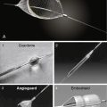
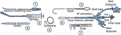
Once the diagnosis of mitral stenosis is confirmed after successful transseptal puncture, the balloon catheter can be prepared. The balloon catheter comes packaged with all the components necessary for the dilatation procedure (Fig. 16-4). These include:
• A balloon-stretching metal tube
• A calibrated inflation syringe specifically matched to each balloon
• A rigid 12F to 14F plastic dilator
• A 0.025-inch spring-tipped exchange guidewire
• A stylet for manipulating the balloon across the mitral valve after it has been placed in the left atrium
• Calipers for measuring the balloon diameter and confirming its inflated size
Balloon Valvotomy
The major steps in valvotomy are illustrated diagrammatically in Figure 16-5. The 0.025-inch spring guidewire is advanced through the Mullins sheath into the left atrium with the fully coiled distal portion out of the sheath and positioned in the roof of the atrium. The Mullins sheath is withdrawn over the guidewire with the guidewire remaining in the left atrium. The dilator is advanced through the skin and then into the atrial septum, where it may be passed through the septal puncture as shown in Figure 16-5. The dilator is left sitting in the septal puncture for several seconds to stretch the septal tissue. The dilator is removed and the balloon catheter is passed over the guidewire via the 14F sheath and then across the atrial septum.
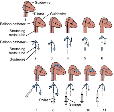
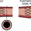
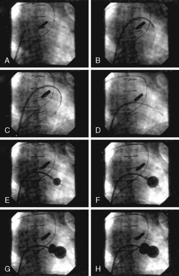
To cross the mitral valve, the tip of the balloon is inflated and the steering stylet is passed into the catheter for its full length. It is important to completely advance the steering stylet within the shaft of the catheter. The stylet is then rotated in a counterclockwise direction as the balloon catheter is advanced and withdrawn over a 2- to 5-cm range, allowing the tip of the balloon to find its way across the mitral valve in a manner similar to that in which a pulmonary artery flotation catheter crosses from the right atrium through the tricuspid orifice into the right ventricle. As the balloon passes across the mitral orifice, the stylet is withdrawn about 5 to 10 cm. The balloon must be advanced gently and moved forward and backward to make sure it is free of entanglements in the subvalvular apparatus. The stylet may be gently bent to accentuate its curve to facilitate passage of the balloon across the mitral valve if initially crossing the valve is very difficult (Fig. 16-6). A useful observation during balloon inflation is the “popping sign” denoting splitting of one or both commissures. During the final portion of the inflation, one observes the inferior or superior margin of the mid section of the balloon suddenly popping outward. This is a welcome sign, which shows a clear decrease in gradient due to the commissurotomy.
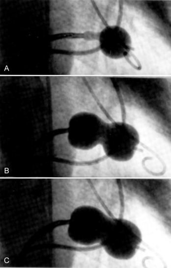
Stepwise Balloon Inflation
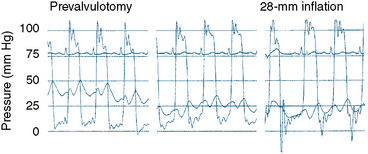
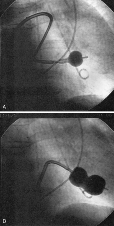
If a transmitral gradient persists and no significant increase in mitral regurgitation has occurred, another balloon inflation is performed at an inflated diameter 1 mm greater than the preceding inflation, as shown in Figure 16-7. This sequence is repeated until either an increase in mitral regurgitation or a sufficient decrease in the transmitral gradient occurs. Balloons can be overinflated by 1 to 2 mm diameter by using an additional 1 to 2 mL inflation volume above the maximal calibrated balloon size. If sufficient reduction in gradient is not achieved after maximal or supermaximal inflation, a larger balloon size can be used.
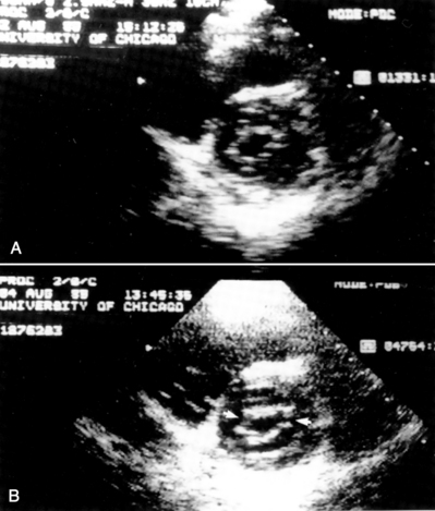
It is very useful to monitor the effect of each balloon inflation in the mitral valve by echocardiography in the catheterization laboratory. Of course, the procedure may be performed without this adjunct, but monitoring of the results is facilitated by echo examination. An in-lab Doppler examination will demonstrate if mitral regurgitation is increased. More importantly, the short-axis two-dimensional examination will show the degree of commissural separation (Fig. 16-8). Note the degree of commissural fusion in the short-axis examination before the balloon dilatation. Separation of one commissure while the other remains fused will facilitate the decision to proceed with further balloon inflations. If mitral regurgitation is not worsened, attempts to complete commissurotomy may be pursued. Conversely, if one commissure is opened completely and a significant amount of mitral regurgitation has developed, this will signify at least an adequate result.
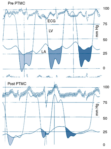
The transmitral pressure gradient is the simplest parameter to monitor between balloon inflations. The absolute level of left atrial pressure is extremely important as well. In general, if the left atrial pressure remains constant or decreases after successive balloon inflations, mitral regurgitation has not yet become limiting. When the mean left atrial pressure rises following balloon inflation, even if a large V wave has not occurred, mitral regurgitation may have worsened significantly. If in-lab echocardiography is not available and left atrial pressure is increasing, a repeat left ventriculogram should be performed. The decision to proceed with further balloon inflations is among the most difficult to make. Use of all available information, including two-dimensional and Doppler echocardiography, left atrial pressure and wave form (Fig. 16-7), auscultation, and ventriculography, is important. Hemodynamics before and after Inoue balloon valvuloplasty are shown in Figure 16-9.
Technical Considerations
If the interatrial septum is crossed in a relatively superior or anterior location, passing the balloon across the mitral valve may be difficult. In this circumstance, clockwise rather than counterclockwise rotation of the stylette will “bank” the balloon off the posterior atrial wall and allow it to cross into the left ventricle after making a loop, as seen in Figure 16-10. This alternative approach is sometimes limited by the short length of the balloon catheter shaft.
Balloon Aortic Valvuloplasty
Indications
There are currently six clinical situations in which BAV is useful.
1. Predilation during transcatheter aortic valve implantation procedures. This method will be discussed in Chapter 17.
2. Cardiogenic shock. Patients who present with aortic stenosis and cardiogenic shock may be stabilized for the short term.
3. Congestive heart failure preceding aortic valve replacement. Among patients with severe left ventricular dysfunction or shock in whom aortic valve replacement is planned, balloon dilatation may be performed to allow improvement in left ventricular performance before surgery. Prerenal azotemia associated with their medical therapy may improve after aortic valve prolapse.
4. Preparation for major noncardiac surgery. Patients found to have aortic stenosis during the evaluation for major noncardiac surgery may undergo valvuloplasty. This is especially useful for patients with malignancies.
5. Preparation for hospice transfer. Hospital-bound patients with severe aortic stenosis who are not candidates for valve replacement surgery may undergo balloon dilatation with successful short-term improvement. This is useful for patients who are dependent on intravenous pressors and in an intensive care unit. Although valvuloplasty does not improve their long-term prognosis, it may allow them to be transferred to a regular floor or discharged from the hospital so that they may have a better quality of life, at least in the short term.
6. Diagnostic test in low gradient, low output aortic stenosis. There is a group of patients in whom balloon valvuloplasty may be performed as a diagnostic test. This is useful when the valve area is between 0.8 and 1.0 cm2 with low cardiac output and a low transvalvular pressure gradient. In this group of patients, the severity of valvular stenosis is especially difficult to ascertain. Poor ventricular function has made therapy in this group difficult. In the past, valve replacement could be performed and, if the patient had improvement in left ventricular function, then survival was good. Unfortunately, for those patients who did not show improvement in left ventricular performance, perioperative mortality was very high. Balloon dilatation may be performed and serial echocardiography used to monitor changes in left ventricular function. If symptoms and left ventricular performance improve with opening of the aortic valve using valvuloplasty, later valve replacement surgery can be undertaken with a high expectation of long-term success.
Technique of BAV
Retrograde Technique
After the transvalvular gradient and cardiac output determinations have confirmed the presence of severe aortic stenosis, the arterial sheath is exchanged for a 10F or 12F sheath. This exchange is performed over an extra-stiff 0.035- or 0.038-inch guidewire to minimize the chance of the large arterial dilator perforating the iliac vessels. The sheath is exchanged over a 360-cm extra-stiff wire that is left curled in the left ventricular apex. To maximize the safety of the tip of this wire in the left ventricle, a “ram’s horn” curve is put on the end of the guidewire (Fig. 16-11). This is done by grasping the wire between the thumb and the edge of a curved hemostat and pulling along the wire rapidly in the same manner one uses to put a curl on gift wrapping ribbon. After the sheath has been exchanged and flushed, it is connected to arterial pressure, and a valvuloplasty balloon catheter is passed over the wire and across the aortic valve. The balloon diameter is selected to approximate a balloon to aortic annulus ratio of between 0.9 and 1.2. The annulus is most easily measured echocardiographically. The optimal balloon-to-annulus ratio has not been established. Most females can be treated with a 20-mm balloon and most males with a 22-mm balloon, but a smaller annulus size should be an indication for a smaller balloon. The necessary arterial sheath size varies among the currently available balloon manufacturers and balloon sizes.
Balloon Inflation
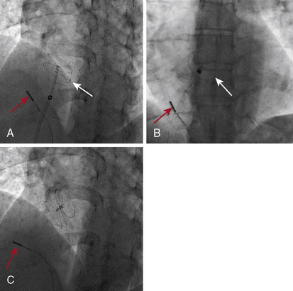
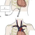
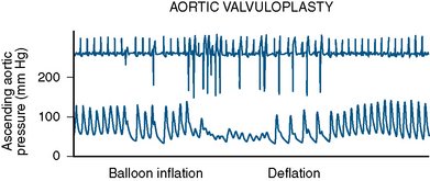
Initially the balloon is inflated via a high-pressure stopcock using a 60-mL syringe partially filled with dilute saline and contrast mixture. The dilute mix (7 to 9 parts of saline to 1 part of contrast) minimizes the viscosity of the solution while at the same time maintaining fluoroscopic visibility. In addition, high-osmolarity conventional contrast is less viscous than low osmolarity. A 10-mL syringe filled with contrast mixture is placed on the sidearm of the high-pressure stopcock used for inflating the balloon. After the 60-mL syringe has been used to inflate the balloon as much as possible, the operator flips the stopcock so that the smaller syringe can be used to inject additional saline/contrast mixture under very high pressure. This “boost” in inflation is very important to achieve maximal balloon expansion. The balloon can be appreciated to completely expand or to “plump” out along its sides when this is done. Adequate valve dilatation is usually not achieved unless this can be accomplished. Hypotension and ventricular tachycardia are typical during balloon inflations (Fig. 16-12).
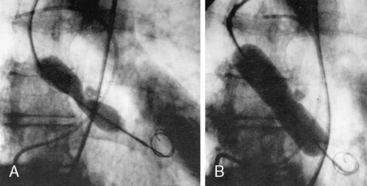
As soon as balloon deflation commences, pacing can be stopped and the balloon can be pulled back in the aortic root while maintaining the guidewire in the left ventricle. It is obviously important to minimize the time of rapid pacing. It requires some practice with a team to start pacing, inflate the balloon, deflate the balloon, and stop pacing smoothly. This allows pressure to recover as rapidly as possible. Once the balloon inflation has been performed without boosting to determine how well the patient will tolerate the inflations, a second inflation is performed to maximal balloon inflation (Fig. 16-13). If the balloon has not ruptured, a third inflation can be performed to ensure optimal dilatation. It is thus important to prepare the balloon very carefully to be sure that no small air bubbles remain during test inflations outside the body. After maximal inflation, the balloon is withdrawn over the guidewire and removed from the sheath. Current generation balloons rupture infrequently, but when they do, the balloon and sheath are removed together as a unit. The ruptured balloon material is often hard to get all the way back into the sheath. Pulling too forcefully will tear off the end of the balloon shaft. Frequently, as the balloon is pulled into the sheath, it will cause the sheath to concertina; thus firm pressure to withdraw the balloon partway into the sheath is important, and then the combined catheter and sheath are removed as a unit. A new sheath can be introduced over the wire and a diagnostic pigtail catheter inserted in the left ventricle to evaluate the final valvuloplasty result.
Procedural End Point
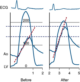
If the transvalvular gradient has fallen by more than 50% and if cardiac output is at least unchanged or has risen, successful valve dilation has been accomplished (Fig. 16-14). In some cases evaluation of valve resistance is helpful (Fig. 16-15). Resistance over 250 dynes/sec/cm−5 is consistent with persistent stenosis while values below 200 dynes/sec/cm−5 signify relief of obstruction.
Antegrade Technique for Aortic Valvuloplasty
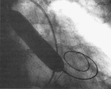
It is possible to perform aortic valvuloplasty via a transseptal puncture with passage of the balloon through the left ventricle and antegrade across the aortic valve. Advantages of this approach include obviating the need for a large-caliber arterial sheath and the potential to use larger balloons that can be easily inserted on the arterial side. A 14F sheath is placed in the right femoral vein. An image of antegrade aortic valvuloplasty is shown in Figure 16-16.

American College of Cardiology/American Heart Association. ACC/AHA guidelines for the management of patients with valvular heart disease. A report of the American College of Cardiology/American Heart Association Task Force on Practice Guidelines (Committee on Management of Patients with Valvular Heart Disease). J Am Coll Cardiol. 1998;32:1486–1588.
Bahl V.K., Chandra S., Goswami K.C., et al. Balloon aortic valvuloplasty in young adults by antegrade, transseptal approach using Inoue balloon. Cathet Cardiovasc Diagn. 1998;44:297–301.
Bernard Y., Etievent J., Mourand J.L., et al. Long-term results of percutaneous aortic valvuloplasty compared with aortic valve replacement in patients more than 75 years old. J Am Coll Cardiol. 1992;20:796–801.
Carlson M.D., Palacios I., Thomas J.D., et al. Cardiac conduction abnormalities during percutaneous balloon mitral or aortic valvotomy. Circulation. 1989;79:1197–1203.
Cohen D.J., Kuntz R.E., Gordon S.P.F., et al. Predictors of long-term outcome after percutaneous balloon mitral valvuloplasty. N Engl J Med. 1992;327:1329–1335.
Cribier A., Remadi F., Koning R., et al. Emergency balloon valvuloplasty as initial treatment of patients with aortic stenosis and cardiogenic shock. N Engl J Med. 1992;326:646.
Eisenhauer A.C., Hadjipetrou P., Piemonte T.C. Balloon aortic valvuloplasty revisited: the role of the Inoue balloon and transseptal antegrade approach. Catheter Cardiovasc Interv. 2000;50:484–491.
Fatkin D., Roy P., Morgan J.J., Feneley M.P. Percutaneous balloon mitral valvotomy with the Inoue single-balloon catheter: commissural morphology as a determinant of outcome. J Am Coll Cardiol. 1993;21:390–397.
Feldman T. Hemodynamic results, clinical outcome, and complications of Inoue balloon mitral valvotomy. Cathet Cardiovasc Diagn Suppl. 1994;2:2–7.
Feldman T. Percutaneous suture closure for management of large French size arterial and venous puncture. J Intervent Cardiol. 2000;13:237–242.
Feldman T., Carroll J.D., Herrmann H.C., et al. Effect of balloon size and stepwise inflation technique on the acute results of Inoue mitral commissurotomy. Cathet Cardiovasc Diagn. 1993;28:199–205.
Feldman T., Carroll J.D., Herrmann H.C., N. American Inoue Investigation, et al. Mitral regurgitation (not restenosis) is the most frequent indication for valve replacement after balloon mitral valvotomy. J Am Coll Cardiol. 1995;25:64A.
Feldman T., Glagov S., Carroll J.D. Restenosis following successful balloon valvuloplasty: bone formation in aortic valve leaflets. Cathet Cardiovasc Diagn. 1993;29:1–7.
Feldman T., Herrmann H.C., Carroll J.D., N. American Inoue Investigation, et al. Balloon valvotomy for non-ideal commissurotomy candidates. J Am Coll Cardiol. 1995;25:90A.
Feldman T., Herrmann H.C., Inoue K. Technique of percutaneous transvenous mitral commissurotomy using the Inoue balloon catheter. Cathet Cardiovasc Diagn Suppl. 1994;2:26–34.
Fusman B., Faxon D., Feldman T. Hemodynamic rounds: transvalvular pressure gradient measurement. Catheter Cardiovasc Interv. 2001;53:553–561.
Hung J.S., Lin F.C., Chiang C.W. Successful percutaneous transvenous catheter balloon mitral commissurotomy after warfarin therapy and resolution of left atrial thrombus. Am J Cardiol. 1989;64:126–128.
Inoue K., Feldman T. Percutaneous transvenous mitral commissurotomy using the Inoue balloon catheter. Cathet Cardiovasc Diagn. 1993;28:119–125.
Isner J.M. Acute catastrophic complications of balloon aortic valvuloplasty. The Mansfield Scientific Aortic Valvuloplasty Registry Investigators. J Am Coll Cardiol. 1991;17:1436–1444.
Lau K.W., Hung J.S. A simple balloon sizing method in Inoue balloon percutaneous transvenous mitral commissurotomy. Cathet Cardiovasc Diagn. 1995;35:183.
Letac B., Crivier A., Koning R., et al. Aortic stenosis in elderly patients aged 80 or older. Treatment by percutaneous balloon valvuloplasty in a series of 92 cases. Circulation. 1989;80:1514–1520.
Levin T., Feldman T., Carroll J.D. Effect of atrial septal occlusion on mitral area after Inoue balloon valvotomy. Cathet Cardiovasc Diagn. 1994;33:308–314.
Manga P., Singh S., Brandis S., et al. Mitral valve area calculations immediately after percutaneous balloon mitral valvuloplasty: effect of atrial septal defect. J Am Coll Cardiol. 1993;21:1568–1573.
Manjunath C.N., Srinivasa K.H., Ravindranath K.S., et al. Balloon mitral valvotomy in patients with mitral stenosis and left atrial thrombus. Catheter Cardiovasc Interv. 2009;74:653–661.
McKay C.R., Kawanishi D.T., Kotlewski A., et al. Improvement in exercise capacity and exercise hemodynamics 3 months after double-balloon, catheter balloon valvuloplasty treatment of patients with symptomatic mitral stenosis. Circulation. 1988;77:1013–1021.
McKay C.R., Kawanishi D.T., Rahimtoola S.H. Catheter balloon valvuloplasty of the mitral valve in adults using a double-balloon technique. JAMA. 1987;257:1753–1761.
Moreno P.R., Jang I.K., Newell J.B., et al. The role of percutaneous aortic balloon valvuloplasty in patients with cardiogenic shock and critical aortic stenosis. J Am Coll Cardiol. 1994;23:1071–1075.
National Heart, Lung and Blood Institute. Balloon valvuloplasty registry: complications and mortality of percutaneous balloon mitral commissurotomy. Circulation. 1992;85:2014–2024.
Nishimura R.A., Holmes D.R.Jr, Michela M.A. Follow-up of patients with low output, low gradient hemodynamics after percutaneous balloon aortic valvuloplasty: the Mansfield Scientific Aortic Valvuloplasty Registry. J Am Coll Cardiol. 1991;17:828–833.
Otto C.M., Mickel M.C., Kennedy J.W., et al. Three-year outcome after balloon aortic valvuloplasty. Insights into prognosis of valvular aortic stenosis. Circulation. 1994;89:642–650.
Petrossian G.A., Tuzcu E.M., Ziskind A.A., et al. Atrial septal occlusion improves the accuracy of mitral valve area determination following percutaneous balloon mitral valvotomy. Cathet Cardiovasc Diagn. 1991;22:22–24.
Post J.R., Feldman T., Isner J., et al. Inoue balloon mitral valvotomy in patients with severe valvular and subvalvular deformity. J Am Coll Cardiol. 1995;25:1129–1136.
Reyes V.P., Raju B.S., Wynne J., et al. Percutaneous balloon valvuloplasty compared with open surgical commissurotomy for mitral stenosis. N Engl J Med. 1994;331:961–967.
Safian R.D., Berman A.D., Diver D.J., et al. Balloon aortic valvuloplasty in 170 consecutive patients. N Engl J Med. 1988;319:125–130.
Solomon L.W., Fusman B., Jolly N., et al. Percutaneous suture closure for management of large French size arterial puncture in aortic valvuloplasty. J Invasive Cardiol. 2001;13:592–596.
Waller B.F., McKay C., VanTassel J., et al. Catheter balloon valvuloplasty of stenotic porcine bioprosthetic valves. Part II: mechanisms, complications, and recommendations for clinical use. Clin Cardiol. 1991;14:764–772.