[level-membership-for-orthopaedics-category]
Chapter 40 Patellofemoral Disorders
Correction of Rotational Malalignment of the Lower Extremity
INTRODUCTION
This chapter reviews the concept of torsional malalignment of the lower limb and its importance on patellofemoral (PF) pathology. This topic was first well reviewed by Stan James, M.D., in which he introduced the term “miserable malalignment.”15 His classic description is highly recommended reading.
Confusion exists in the literature regarding the term malalignment. Insall and coworkers13 in 1976 defined patellar malalignment as being either an increased Q-angle or a high-riding patella. No other options were considered. Then, Insall and coworkers observed that “an increased Q-angle is usually associated with increased femoral anteversion and external tibial torsion. In the presence of these abnormalities when the hip and ankle joints are normally aligned, the patella faces inward and motion of the knee occurs about an axis which is rotated medially compared with the axes of the hip and ankle joints.” These authors recommended a medial tibial tubercle transfer or “patellar realignment” to treat this torsional malalignment, and it is no small wonder that the investigation reported that 61% of the patients remained symptomatic. Clearly, the underlying pathoanatomy had not been addressed. Tibial tubercle transfer has been shown to cause external rotation of the tibia on the femur rather than pull the patella medially into the trochlea.17 In addition, this procedure has been shown to increase medial compartment loading20 and medial facet loading. This author does not use the term “patellar malalignment” or “patellar realignment,” and reserves the term malalignment to refer only to a limb that deviates from normal in any one plane or any combination of the three anatomic planes: coronal (frontal), sagittal, or transverse (horizontal). Limb alignment is a direct result of the shape of the bones in the limb, but malalignment may be the result of acquired cartilage or ligament loss in which the deformity exists at the joint and not the bones.
Over 50 independent observations have been reported in the literature to be associated with anterior knee pain, chondromalacia, patellar instability, or patellar malalignment (Table 40-1). Whereas these factors may be very important, objective measurement tools are lacking. No study has ever tried to assess all these variables in a single cohort of patients, and even if this were undertaken, the lack of objective measurement techniques would make the study invalid. If these variables are indeed important, then any study would need to incorporate accurate measurements of each. The relative importance of each will need to be developed. Without this, clinicians are left with a realization that data do not exist to guide in the knowledge of pathomechanics, diagnosis, and treatment and that we depend only on unrelated clinical observations and some very basic laboratory studies.
TABLE 40-1 Cited Contributions to Patellofemoral Dysfunction
| Genu valgum | Genu varum |
| Femoral anteversion | Femoral retroversion |
| Excess external tibial torsion | Excessive internal tibial torsion |
| Outerbridge ridge | Trochlear dysplasia |
| Shallow trochlea | Short lateral trochlea |
| Increased Q-angle | Decreased Q-angle |
| Excessive lateral quadriceps pull | Insufficient vastus medialis obliquus |
| Decreased patellar surface contact area | Abnormal patellar spin |
| Patellar dysplasia | Patella alta |
| Patella baja (infera) | Menisectomy |
| Laxity of ACL, PCL, MCL, or FCL | Rotatory instability |
| Iliotibial band contracture | Quadriceps contracture |
| Achilles contracture | Retinacular contracture |
| Retinacular laxity | Hyperpronation |
| Pes planus | Tibial tubercle–trochlear groove distance (TT/TG) |
| Patellar malalignment | Patellar instability |
| Patellar subluxation | Medial patellar dislocation |
| Lateral patellar dislocation | Chondral softening |
| Genu recurvatum | Patellar tilt |
| Patellar shift | Abnormal (mal) tracking |
| VMO dysplasia | J sign |
| A sign | Bayonet sign |
| Crossing sign | Trochlear bump |
| Patellar thickness | Knee flexion contracture |
| Infrapatellar contracture | VMO/VLO ratio |
| Rearfoot varus | Patellar glide |
| Quadriceps tendon width | Flexor hallucis longus tendon entrapment |
| Flexor hallucis dysfunction | Increased lumbosacral instability |
| Hip flexion contracture | Abdominal oblique: rectus femoris + psoas imbalance |
| Quadriceps atrophy | Pelvic abductor weakness |
| Increased thoracolumbar extension | Inward pointing knee |
| Female gender |
ACL, anterior cruciate ligament; FCL, fibular collateral ligament; MCL, medial collateral ligament; PCL, posterior cruciate ligament; VLO, vastus lateralis obliquus; VMO, vastus medialis obliquus.
Table 40-1 shows the variables related to PF syndrome, anterior knee pain, PF instability, chondromalacia, and PF arthritis. The contributions of these variables need to be defined, measured, and validated before any meaningful outcome studies can be completed. It is critical to simplify the confusing clinical picture created by so many variables. Toward this end, this author considers that there are only four independent but related variables to assess. Each of the conditions just discussed can be fitted into one of these four: skeletal geometry, ligaments, articular cartilage (patella and trochlea), and musculotendinous units.
BASIC ASSUMPTIONS
Critical Points BASIC ASSUMPTIONS


This author uses physical examination, coronal standing radiographs, sagittal radiographs, and rotational computed tomography (CT) studies to assess limb alignment. Physical examination and stress radiography43 are used to assess ligament insufficiency. Double-contrast CT arthrography with fine cuts determines the thickness of articular cartilage and the location and size of various focal defects. The usual clinical tests of strength, orientation, and flexibility (e.g., Ober test, prone rectus test, straight leg raising, Achilles contracture) are used to assess musculotendinous units.
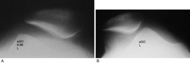
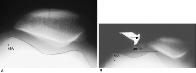
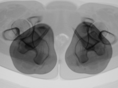
Patellar instability results from a loss of the patellar stabilizers and often an excess of displacement forces. The patellar stabilizers are the trochlear groove and the ligaments (both the medial and the lateral patellofemoral ligaments) and the medial and lateral meniscopatellar ligaments. Brattström,2 as early as 1964, demonstrated that in recurrent dislocation of the patella, a flattening or dysplasia of the trochlear groove is nearly always present. Dejour and colleagues6 demonstrated that this dysplasia is often in the proximal portion of the trochlea not seen on an axial patellofemoral radiograph. This can be measured on a true lateral knee radiograph by recognizing the floor of the groove and the anterior projections of the medial and lateral condyles. For lateral patellar dislocation to occur, the medial patellofemoral ligament (MPFL) must be injured. A number of authors including Christoforakis and associates4 and Desio and colleagues8 have demonstrated in the laboratory that the lateral retinaculum provides up to 19% of the resistance against lateral displacement; thus, the patella is usually more unstable after lateral retinacular release. Medial dislocation is a distinct possibility and this author reported 70 cases confirmed with stress radiography in 1990 (Annual Meeting of the American Academy of Orthopaedic Surgeons). The diagnosis of instability requires a force and displacement examination and stress radiography may provide documentation (Figs. 40-1 and 40-2), because unstressed radiographs are normal but stress application demonstrates obvious excessive displacement.
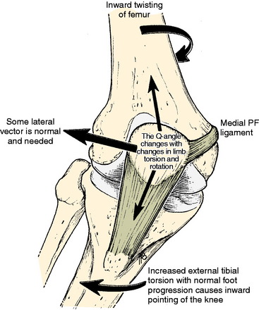
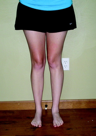
A frequent contributing cause of patellar dislocation is the existence of an abnormally high displacement force. This most often occurs when the direction of the lateral quadriceps vector is increased. This commonly occurs when the femur twists away from under the patella, most often in the direction of medial rotation. This is usually due to some torsional abnormality of the lower limb (Fig. 40-3). In the face of such excess displacement forces, a PF ligament reconstruction may fail.
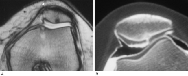
Arthrosis or chondromalacia exists when articular cartilage fails as the force per unit area exceeds biologic tolerance. For acute fractures of articular cartilage, this may be in the range of 20 MPa. In the case of chronic overload due to a too small articular surface area or too much body weight, muscle loading or long lever arms with chronic pressure exceeding 5 MPa may lead to arthrosis. Articular fractures exist approximately 90% of the time after acute patellar dislocation.31 Although magnetic resonance imaging (MRI) is often used to demonstrate articular cartilage lesions, Figure 40-4 gives an example of pathology clearly seen with double-contrast CT arthrography not visualized on MRI. Rotational malalignment is often a major contributing cause of pain, instability, and cartilage injury, but the evidence of how much benefit can be derived from rotational osteotomy in the presence of instability and arthrosis is unknown.
HOW DOES LONG BONE TORSION AFFECT THE PF JOINT?
The knee joint axis moves straight forward during gait, with a small (<10°) turning inward and outward.27 The foot also tends to move in a fairly constant direction (foot progression angle).28,37 The geometry of the lower extremity skeleton largely determines the direction of load applied at the PF joint, with the amount of load depending on the body mass, the length of the lever arms, the surface area of the PF joint, and the velocity of the moving system. If the knee joint axis is twisted out of its normal plane of flexion and extension while the quadriceps is contracting, a side-directed force is created that acts on the patella, attempting to displace it. This causes an increased strain on the PF ligaments and retinaculum and an imbalanced direction of force on the PF articular surface.
Critical Points HOW DOES LONG BONE TORSION AFFECT THE PATELLOFEMORAL JOINT?


If these side-directed vectors exceed biologic tolerance, either instability or arthrosis may result. For example, an inward pointing of the knee increases the lateral direction of pull of the quadriceps. Therefore, the pull on the MPFL (and also medial retinaculum and medial meniscopatellar ligament) is increased and the direction of pressure on the patella is altered, creating an increase on the lateral facet and a decrease on the medial facet (Fig. 40-5). The radiographic appearance of subchondral density under the patellar facets is a useful clue to the mechanical environment (Fig. 40-6).
Maximum energy conservation during gait is due to precise anatomy and joint kinematics.34 Abnormalities in normal bony anatomy or joint motions distort the normal force vectors needed to transfer the body mass to the ground. Deviations in normal limb alignment may result in the knee joint flexion-extension axis advancing sideways while the body moves forward. These deviations include femoral anteversion or retroversion, excess internal or external tibial torsion, genu valgum or varus, hyperpronation, and Achilles contracture.
The foot progression angle (FPA) is generally defined as the angle between the long axis of the foot and the direction of body progression and averages 10° to 15°.28,37 It has been shown that the FPA remains similar despite differences in the torsion of the tibia or femur.37 It is likely that this is because proper ankle dorsiflexion cannot occur during gait if the ankle joint axis is not aligned with the direction of forward movement or because this presents the most stable position of the foot on the ground. Hip rotation must vary if the torsion of the long bones changes and the FPA stays constant. Alterations in both femoral and tibial torsion change the effective lever arm of the hip stabilizers1 and may account for the frequency of soft tissue complaints around the hip and pelvis, as well as the increased pelvic tilt and lumbar lordosis seen in these patients. Examples of the change in the position of the hip and knee with a constant foot progression angle and changes in femoral and tibial torsion are seen in Figures 40-7 to 40-11.
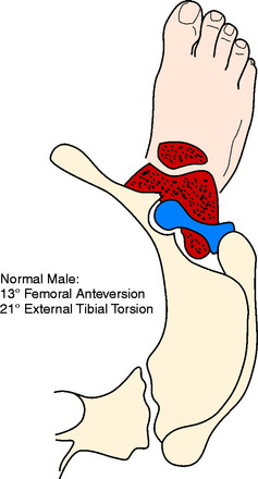
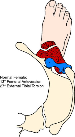
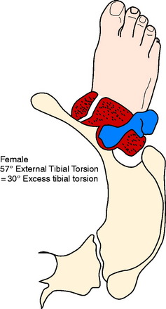
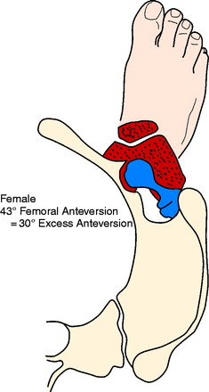
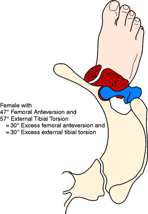
Figures 40-7 to 40-11 are drawn with an FPA of 13° (Seber average) for a normal male torsional alignment (Fig. 40-7), a normal female torsional alignment (Fig. 40-8), a female with 30° excess external tibial torsion (Fig. 40-9), a female with 30° excess femoral anteversion (Fig. 40-10), and a female with both 30° excess tibial external torsion and 30° excess femoral anteversion (Fig. 40-11). One may study the variations in knee joint progression with these common abnormal patterns. Yoshioka and associates47–49 found identical femoral anteversion in both males and females, equal genu valgus in both males and females, but an increase in external tibial torsion and in foot external rotation in females over males. This increase in external foot rotation may account for the apparent increased genu valgus in females, the increased incidence in PF symptoms in females, and even for the increased incidence of ACL tears in females.
BIOMECHANICAL EVIDENCE RELATING LIMB TORSION WITH PF INSTABILITY AND PAIN
A change in PF contact areas and pressures was noted after alteration of femoral or tibial torsion or rotation by Lee and coworkers22–24 Hefzy and associates,12 and van Kampen and Huiskes.45 Kiljowski and colleagues18 (unpublished data) placed lower limbs (femoral head to foot) in a frame with a clamp, attaching the femoral head to a vertical post that allowed the knee flexion to be altered by sliding the femoral head up and down the post. The foot was held in a position of normal FPA and an osteotomy was performed in the shaft of the femur, allowing rotation. PF contact pressures and MPFL strain were measured while the osteotomy changed the femoral torsion 15° and 30°, both inward and outward. At 30° knee flexion, lateral facet pressure increased an average of 30%, with a 30° increase in femoral anteversion, while medial facet pressures were decreased. Strain in the MPFL increased 57% after a 30° increase of internal femoral torsion. Fujikawa and coworkers11 in a biomechanical study that measured PF contact pressures concluded that if an angular deformity and a torsional deformity coexist, the rotatory component causes the greater PF changes. These authors also noted that when a varus deformity was created, the greater the varus deformity, the less the PF congruence.


CLINICAL EVIDENCE RELATING LIMB TORSION TO PF INSTABILITY AND PAIN
Brattström2 in 1964 measured trochlear depth in a group of patients with recurrent dislocation of the patella and confirmed that a shallow trochlea was always present. This author also defined the Q-angle and pointed out the change in Q-angle as a result of changes in limb rotation. He reviewed the literature on the rotational femoral osteotomy as described by Graser (1904), Fürmeier (1953), Kiesselbach (1956), and Vinditti and Forcella (1958) and concluded that the “femoral osteotomy is a big operation that demands prolonged after treatment. I have not encountered any instance of recurrent dislocation of the patella that justified my suggesting an operation of this nature to the patient.” Takai and associates41 measured femoral and tibial torsion in patients with unicompartmental arthrosis in either the medial, the lateral, or the PF compartment and found the highest correlation to be that of PF arthrosis with increased femoral anteversion (23° anteversion in the osteoarthritis group vs. 9° anteversion in the control group). Janssen16 found a high correlation between patellar dislocation and an increase in medial femoral torsion and speculated that this medial femoral torsion was also responsible for the development of trochlear dysplasia. Lerat and colleagues25,26 noted a significantly increased association of internal femoral torsion with both patellar instability (P < .0001) and patellar chondropathy (P < .001). Stroud and coworkers40 followed 92 patients who at age 5 showed 30° greater medial hip rotation (measured in extension) than lateral rotation. At age 24, PF pain was noted by 30% in the increased medial rotation group compared with only 8% in the control group (P < .001). Winson and associates46 found that 70% of adolescents undergoing arthroscopy for anterior knee pain had an increased internal torsion of the femur, compared with only 33% of those undergoing arthroscopy for a meniscal or cruciate injury. Turner44 noted increased external tibial torsion in patients with PF instability (25° vs. 19°). Of perhaps great significance to those who believe that muscle strengthening is the key to treating PF symptoms, Nyland and colleagues32 found a significant decrease in vastus medialis and gluteus medius electromyogram amplitude in athletes with clinically increased internal femoral torsion. Arnold and coworkers1 noted that an increase in femoral anteversion of 30° to 40° and decreased abduction moment arm strength of 40 to 50% was enough to impair normal walking, and therefore, those individuals required turning the knee inward to keep the hip from collapsing. This inward pointing of the knee creates high shearing force on the PF joint.
FEMORAL AND TIBIAL TORSION MEASUREMENTS
Femoral anteversion has been measured by a variety of techniques by many authors and recently by Yoshioka and associates47,48 (Fig. 40-12). To measure limb alignment in the horizontal (transverse) plane, a CT rotational study is obtained. This is a CT scan that overlaps cuts from the femoral head, base of the femoral neck or lesser trochanter, the knee joint (either tangent to the posterior condyles or between the medial and the lateral epicondyles), the proximal tibia at the joint and the tibial tuberosity, and the ankle joint (Fig. 40-13). These cuts allow measurement of femoral torsion, tibial torsion, knee torsion, and the tibial tubercle–trochlear groove (TT/TG) distance. CT also allows for the observation of trochlear depth or dysplasia, the position of the patella in the trochlea (unstressed), patellar tilt, and shift and the density of the subchondral trabeculae.
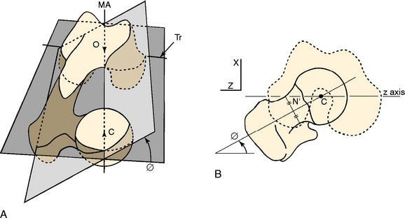
FIGURE 40-12 A, Femoral anteversion or antetorsion (angle ϕ here) may be measured along the center of the femoral neck from the center of the femoral head to the center of the femoral shaft at the base of the neck, and distally either along the transepicondylar axis (Tr) 7.4° or along the tangent of the posterior femoral condyles 13.1°. These differ by about 6°, with a range of 11° retroversion to 22° anteversion. B, This measurement by Yoshioka and associates48 is taken directly off the bone. Murphy and coworkers30 validated a CT measurement along these same lines.
(A, From Yoshioka, Y.; Cooke, T. D. V.: Femoral anteversion: assessment based on function axes. J Orthop Res 5:86–91, 1987, p. 88. Fig 3A; B, from Yoshioka, Y.; Siu, D.; Cooke, T. D. V.: The anatomy and functional axes of the femur. J Bone Joint Surg Am 69:873–880, 1987, p. 875, Fig. 2B.)
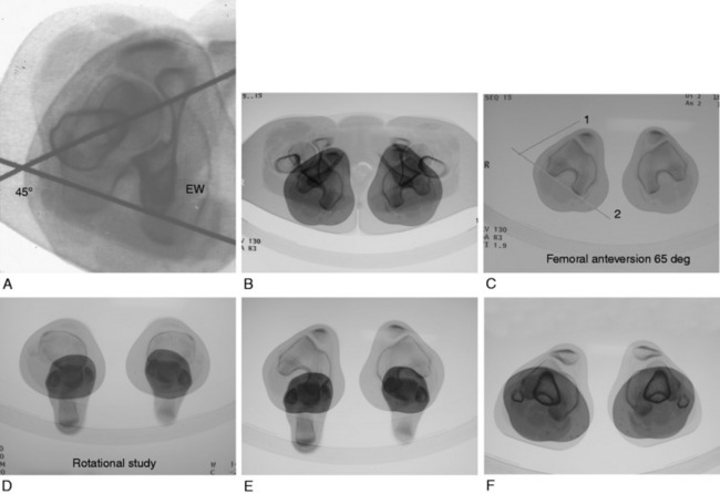
FIGURE 40-13 A, For measuring femoral torsion (anteversion), CT slices taken through the femoral head, the inferior greater trochanter, and the knee joint are superimposed. One line is drawn from the center of the femoral head through the greater trochanter, and a second is tangent to the posterior femoral condyles at the knee joint. B, Hip and knee overlapped, allowing references lines seen in C to be drawn. C, Reference line 1 is taken from the center of femoral head to the center of femur at the level of the lower greater trochanter. Reference line 2 is a tangent to the posterior surface of the femoral condyles. The epicondyles are also readily seen and can be used as a second reference. There is generally a 6° difference between these two choices of reference. D, Tibial torsion can be measured between the axis of the tibial plateau and the ankle joint axis. E, The angle between the epicondylar axis of the femur and the ankle joint axis can be used as a measure of tibial torsion. F, The distance between the tibial tubercle and the center of the trochlear groove (TT/TG) is also provided in the rotational study. Dejour and colleagues6 stated that a distance > 20 mm is abnormal and correlates with objective patellar instability.
Critical Points FEMORAL AND TIBIAL TORSION MEASUREMENTS


CT, computed tomography; TT/TG, tibial tubercle–trochlear groove.
To measure torsion of the femur, the recommendations of Murphy and coworkers30 and Yoshioka and Cooke47 are followed; these superimpose the CT cuts through the center of the femoral head and the base of the femoral neck where the circular nature of the femoral shaft becomes apparent (see Fig. 40-13A–C). A line drawn through the center of each femoral segment becomes the proximal reference. A CT cut through the distal femur where the anteroposterior (AP) dimension of the medial and lateral condyles is greatest allows a line to be drawn tangent to the posterior condylar surface. A second line can be drawn through the medial and lateral epicondyles. Yoshioka and Cooke47 measured femoral torsion (anteversion) directly from the bone in a series of 32 femora and noted an average anteversion of 13.1° in both males and females when the distal measurement was the tangent across the femoral condyles, and 7.4° when measured across the epicondyles (standard deviation [SD], 8°; range, –11°–+22°). It is useful to measure both to avoid an error should dysplasia of the lateral femoral condyle with a short AP distance be present.
Yoshioka and Cooke47 reviewed the literature measuring femoral anteversion by a variety of different techniques and noted that 12 of the 18 reviewed papers reported normal values between 8° and 16°. This author has arbitrarily chosen 13° as the goal for correction. Kuo and associates19 observed various measurement techniques and concluded that CT was accurate, but that the plane radiographic techniques were not. It is often stated that a patient with increased femoral anteversion has a compensatory external tibial torsion. Pasciak and colleagues33 found this not to be the case and found no relation between femoral anteversion and tibial torsion. In a review of over 300 CT rotational studies, the author of this chapter found that with increased femoral anteversion, tibial torsion may be normal, increased external, or increased internal.
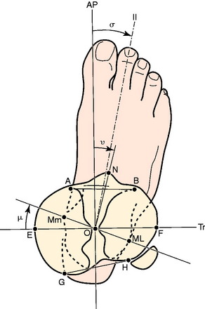
The measurement of tibial torsion by CT has not been standardized. Jakob and coworkers14 described a common sense method superimposing cuts across the proximal tibia and distal ankle joint. The author of this chapter has attempted to use the anatomic measurements of the tibia described by Yoshioka and colleagues49 as a basis for measuring the proximal tibial reference line (Fig. 40-14). Blinded repeat measurements made by an orthopaedic radiologist produced a measurement variation of less than 1°, indicating that reproducible measurements are possible. Yoshioka and colleagues’ anatomic study49 reported a lateral torsion of 21° in males and 27° in females, a significant difference. This was the only difference in geometry noted between males and females in both the tibia and the femur. In addition, these authors noticed a gender difference of 16° between the transverse axis across the tibial plateau and the center of the foot. If this observation is confirmed, it is of major importance because it may explain the widely quoted difference between men and women in the frequency of PF disorders. It may also explain the reported increased incidence of anterior cruciate ligament (ACL) tears in women. Le Damany21 reported 23.7° to be normal tibial torsion. Seber and associates37 calculated external tibial torsion to be 30° (range, 16°–50°) in a group of 50 “normal” (asymptomatic) men, but their measurement technique was unique in selecting the location for drawing the proximal tibial reference. Eckhoff and coworkers9 noted variations between 15° and 30°. Turner44 found 19° (SD, 4.8°) in a control group and 24.5° (SD, 6.3°) in a group with unstable patella. The CT measurements of Sayli and coworkers35 averaged 30° to 35°. Tamari and associates42 recently demonstrated a lack of reliability between currently used measurement methods, which is a major stumbling block in answering the question of how much of an influence altered tibial torsion plays in PF instability and when osteotomy may be useful.
In addition to the just-discussed method taken after Yoshioka and colleagues’ anatomic measurements,49 the author of this chapter also uses the femoral epicondylar axis as the proximal reference for tibial torsion, owing to the interest in the relationship of the knee joint axis to the ankle joint axis and the problem incurred when selecting a line across an oval tibial plateau. The error of twisting across the knee joint while obtaining the CT must be avoided to use this reference.
INDICATIONS
Any variation from optimal skeletal alignment may increase the vector forces acting on the PF joint causing either PF ligament failure with subsequent subluxation or cartilage failure as in chondromalacia or arthrosis or both ligament and cartilage failure. Anterior knee pain may result from these abnormal forces or their consequences (Fig. 40-15).
An inward-pointing knee due to any cause will increase the lateral displacement force on the patella (Figs. 40-16 to 40-18). If this force is great or if the trochlear support is reduced from dysplasia or fracture, the medial ligaments may fail, resulting in lateral patellar instability. The converse is also true. Pain in the medial retinaculum is a common symptom caused by this increased stress. If the trochlear support is normal, the ligament may not fail but the articular load may increase, causing arthrosis. This increased force may be the result of abnormal femoral torsion, abnormal tibial torsion, genu valgum, hyperpronation, Achilles’ contracture, or other conditions. The choice for surgery depends on the relative size of the deformity and the relative surgical risk and morbidity.
SURGICAL STRATEGY
Critical Points WHEN TO CONSIDER OSTEOTOMY AND SURGICAL STRATEGY
Experience suggests that for most cases with torsion of the femur or tibia exceeding 30° from normal, surgery is indicated. For those with torsion exceeding 20° from normal, surgery is thought to be beneficial. For cases with abnormality less than 20°, the accuracy of surgery or the morbidity may not justify the smaller biomechanical changes. Turner’s data44 found 19° average external torsion in a control group and 24.5° in a patellar instability group. In another study, Takai and associates41 found 9° average femoral anteversion in a control group and 23° average in a PF arthrosis group. Therefore, it is possible that very small limb torsional differences are significant.
SURGICAL TECHNIQUE
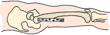
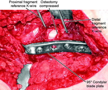
To correct an excess of internal femoral torsion that is not associated with a genu varus or valgus, an intertrochanteric osteotomy has been used since the late 1980s. Prior to that, the author used the technique of intramedullary saw and fixation with an intramedullary nail. However, the antecurvatum of the femoral shaft is destroyed when the curved segments are rotated and the nail can split the distal fragment attempting to compensate (Fig. 40-19). In the original series of patients, cutting the femur from the intramedullary position and fixing with an intramedullary nail, bone stability appeared to be less with more postoperative pain and blood loss. There was a higher incidence of delayed union and one death resulted from apparent fat embolism. Consequently, the intertrochanteric region using an AO 95° condylar blade plate (Figs. 40-20 and Figs. 40-21) for fixation was selected. The intertrochanteric location was chosen to minimize damage to the quadriceps, avoid scarring that may occur between the distal quadriceps and the supracondylar femur with a supracondylar location, and theoretically reduce the abrupt angular change the quadriceps would make with a supracondylar location. It should be noted these decisions are without scientific evidence. If a genu varum or genu valgum is associated with a torsional abnormality and the tibiofemoral angle is abnormal, this deformity must be corrected in the supracondylar region.
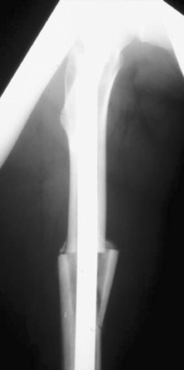
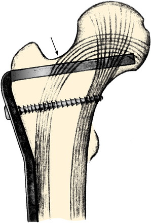
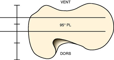
FIGURE 40-21 Blade is inserted into the center of the femoral neck and head.
(From Müller, M. E.; Allgöwer, M.; Schneider, R.; Willenegger, H.: Manual of Internal Fixation, 2nd ed. New York: Springer-Verlag, 1979; p. 93.)
Critical Points SURGICAL TECHNIQUE
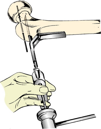
The standard AO/ASIF (Arbeitsgemainshaft für Osteosynthesefragen/Association for the Study of Internal Fixation) technique for hip osteotomy is used. This has been well described. The ability to solidly compress the two osteotomy fragments ensures stability and reduces pain. This compression remains a major advantage of the classic approach. The osteotomy is placed at the level of the proximal third of the lesser trochanter to increase the osteotomy surface contact area and to leave sufficient purchase for the 95° condylar blade plate in the proximal fragment. The blade plate is a tool that controls the correction. One needs to ensure only that the seating chisel for the blade plate enters the femoral neck at the proper height and orientation. The goal is for the blade of the blade plate to be centered in the femoral neck at such an angle that the side plate will sit on the lateral cortex of the femur without altering flexion-extension or varus-valgus. The standard AO tools aid in this goal (Fig. 40-22).
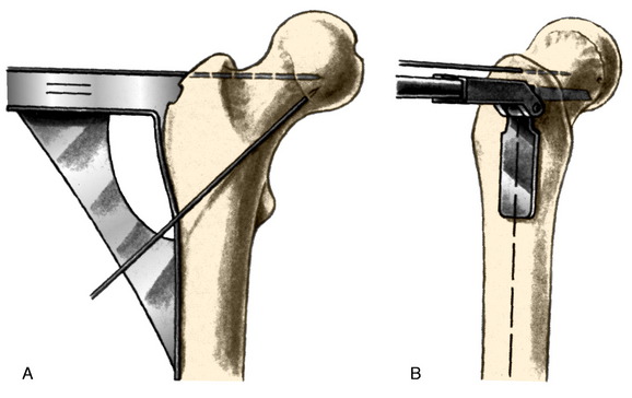
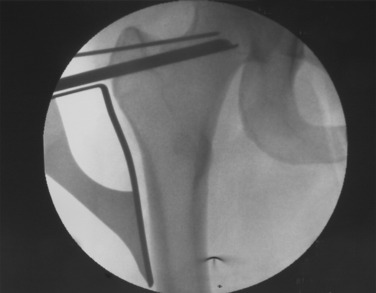
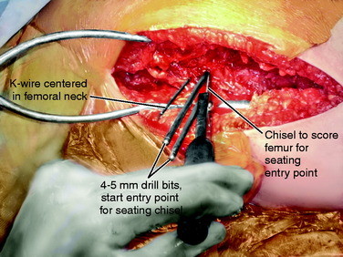
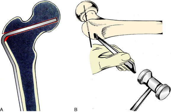
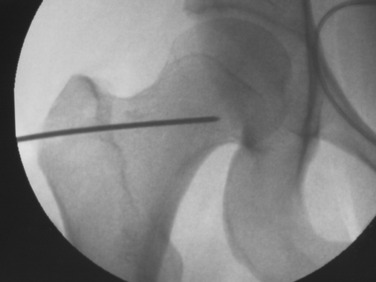
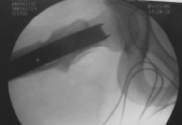
After exposure of the lateral shaft of the femur by elevating the vastus lateralis anteriorly, the condylar plate guide, a mirror image of the 95° condylar plate, is placed along the lateral shaft of the femur. It is moved proximally and distally until an extension along its proximal flat surface lines up just below the center of the femoral head, as seen with x-ray image intensification (Fig. 40-23). A 2.0-mm K-wire is inserted into a 2.5-mm hole drilled into the femoral neck parallel to the top of the condylar plate guide and centered anteriorly and posteriorly in the neck. This hole is placed proximal enough to leave room below it to insert a seating chisel on top of the condylar plate guide. Because of the torsional deformity, the femoral neck is often angled quite anteriorly relative to the knee joint, but its exact direction cannot be seen. Classically, one may expose the neck of the femur anteriorly or slide a K-wire along the anterior cortex of the neck, but this is usually approximate and not exactly in the center line. To find whether this 2-mm K-wire is parallel to the center line of the femoral neck, a frog-leg lateral image is obtained. This normally results in bending of the K-wire against the iliotibial band, but the portion within the femoral neck will indicate whether the direction is appropriate. It is common to need to change these K-wires when they are bent. Obtaining the frog-leg lateral radiographic projection and the ability to slide the 2.0-mm wire in and out of the 2.5-mm hole are useful.
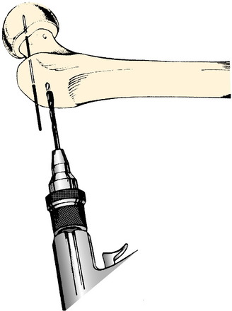
Once the proper position of the K-wire is obtained, the seating chisel for the angled blade is inserted. A window in the lateral cortex of the greater trochanter for the seating chisel may be started with drills (Fig. 40-24). The thickness of the 95° condylar blade is 4.5 mm, allowing a 4.5-mm drill to be used. A triple drill guide is available to attach to the top of the condylar plate guide to ensure the correct drill direction.
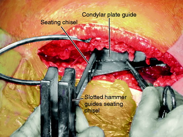
The condylar plate guide and later the seating chisel guide are held parallel to the femoral shaft to ensure the side plate will align with the lateral femoral shaft and there will be no change in flexion or extension (Fig. 40-25). Once the proper position of a K-wire is obtained, a thin chisel is used to cut into the lateral femoral cortex at the top of the properly positioned condylar plate guide. This cut in the cortex will allow the seating chisel for the blade to be advanced without sliding proximally or distally (Fig. 40-26). The condylar plate guide is used repeatedly to check that the varus-valgus angulation is not being changed and also that the flexion-extension angle will not be changed (Fig. 40-27). The seating chisel is advanced slowly until it approaches the center of the femoral head. It is backed out after advancing every 5 mm or so, so that it does not become incarcerated. The slotted hammer is used to prevent twisting of the seating chisel into flexion or extension as it is advanced. The depth of insertion is read off the marks etched on the seating chisel. A chisel is used to remove a small sliver of bone from the inferior edge of the entry site for the blade. This allows the shoulder of the plate to be advanced into the proximal fragment (Figs. 40-28 and Figs. 40-29).
When the seating chisel is removed, a 2.0-mm K-wire may be inserted into the chisel track and this wire will slide into the U corner (Figs. 40-30 and Figs. 40-31). This guarantees that the direction for the blade will not be lost while the osteotomy is completed.
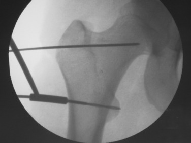
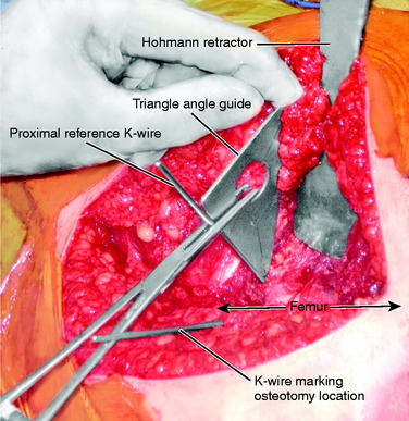
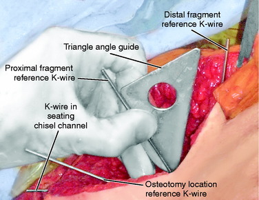
Two anterior-to-posterior K-wires, which are set at the desired angle of correction, are placed in the femur, one proximal and one distal to the selected site for osteotomy (Figs. 40-32 and Figs. 40-33). A 2.5-mm drill is used to create the holes for these two K-wires. These are the markers to indicate the torsional correction. For excess femoral anteversion, the need is to externally rotate the distal fragment. The proximal pin is placed first, far enough anterior and medial that it will not come into conflict with the angled blade plate that will be inserted into the proximal fragment. The distal pin is started in line with the proximal pin in the anterior femoral cortex, but angled from medial to lateral the desired correction amount. Commercially provided triangles of various angles are available to be placed along the proximal K-wire and used as a guide to drill the 2.5-mm hole for the distal 2.5-mm K-wire reference.
Once these reference pins are in place, the osteotomy is completed with a thin saw (Fig. 40-34). The saw blade is kept perpendicular to the axis of the femur, and the image helps ensure that the orientation is proper (Fig. 40-35). Elevators are placed anterior and posterior to the bone to protect the soft tissues, and the image is used to judge the medial depth of the cut. Once the cut is completed, the soft tissues adjacent to the cut are stretched by placing a lamina spreader within the osteotomy (Fig. 40-36). This makes it easier to adjust rotation. Next, the blade plate is inserted into the proximal fragment (Fig. 40-37). The previously placed 2.0-mm K-wire in the seating chisel track makes the direction easier to follow. If the blade is properly in line with the track, it can often be pushed in by hand. After it is correctly placed in the femoral neck and head, it is necessary to impact the blade tightly into the proximal fragment (Fig. 40-38). Usually, a five-hole length side plate is sufficient. A longer-length side plate provides greater leverage but requires a longer incision and surgical approach.
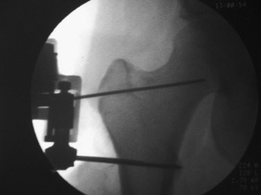
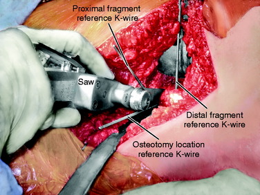
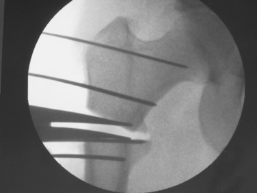
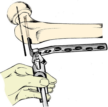
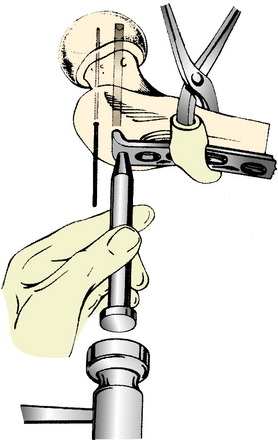
FIGURE 40-38 The impactor is used to seat the plate fully into the proximal fragment.
(From Schauwecker, F.: Practice of Osteosynthesis, 2nd rev. ed. New York: Thieme-Stratton, 1982; p. 190.)
The distal fragment is now externally rotated until the two torsional reference K-wires are parallel and the cortices of the osteotomy surface are well aligned circumferentially (Fig. 40-39). If the blade is not driven sufficiently far into the proximal fragment, it may allow the distal fragment to translate more laterally than the proximal fragment such that the surfaces of the osteotomy do not line up. This can be corrected by removing a small amount of bone from beneath the shoulder of the plate and impacting the plate further into the proximal fragment. Hohmann retractors or clamps may be useful to help align the axis of both fragments while maintaining the rotational correction. Once this position is reached, the articular tension device is attached to the femur distal to the plate (Fig. 40-40). This must be in line with the plate or the rotation will be changed as tension is applied to the plate.
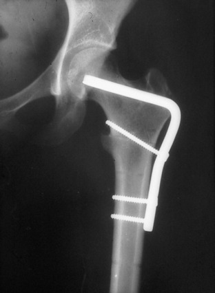
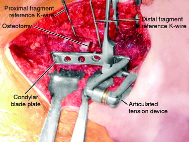
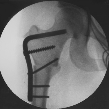
A tension device placed anterior to the plate will cause external rotation of the distal fragment when tension is applied, and a tension device placed posterior to the plate will cause internal rotation of the distal fragment to be introduced. The articular tension device is color-coded, with the red indicating 120 kPa. Using the spanning wrench, an attempt is made to always exceed the 120 kPa indicator (Fig. 40-41). If the screw attaching the tension device to the femoral shaft is bent, the author is confident satisfactory compression of the osteotomy surfaces has been reached. If the blade is not tightly seated in the proximal fragment, it may pull out as tension is placed in the plate. A screw through the proximal plate into the proximal fragment is often required to prevent the blade from backing out with subsequent loss of osteotomy compression (Figs. 40-42 and Figs.40-43). The author has not found that proximal femoral nails or locked plates provide the degree of compression that can be obtained with the angled plates and the articulated tension device.
Rotational osteotomy of the tibia should be performed below the level of the tibial tuberosity. The Q-angle or TT/TG distance is an important biomechanical arrangement that should not be changed. It makes little difference where the osteotomy is performed, because the goal is to realign the knee joint axis with the ankle joint axis in the transverse plane, leaving the trochlea-tubercle relationship normal (Fig. 40-44). The author prefers the proximal tibia below the tubercle for the location of the osteotomy and the angled blade plate for compression, but the geometry of the proximal tibia makes the blade insertion always a problem. With a lateral approach, the side plate will come to lie along the flat surface of the tibia so the angle the blade takes into the proximal fragment will determine rotation, but the precise direction of this is not easily referenced off the flat surface of the tibia. This lack of smooth tibial surface for reference also makes proper insertion in varus-valgus a problem when tension is applied to the plate with the articular tension device. The eccentric loading of the plate may introduce a varus or valgus deformity that must be corrected.
FIGURE 40-44 Excess external tibial torsion is corrected by an internal rotation osteotomy below the level of the tibial tubercle.
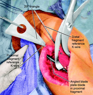
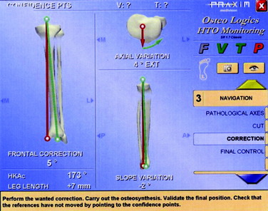
Two 2.5-mm K-wires are placed from front to back in the anterior cortex of the tibia, one proximal and one distal to the anticipated level of osteotomy. These may be parallel or subtend the desired angle of correction in the transverse plane. If they are parallel, the angle between the two after manipulation of the osteotomy fragments indicates the correction angle (Fig. 40-45). If they have been placed at an angle to each other for the desired correction, the pins are brought parallel for judging the desired correction. It is important to have these as reference points before the osteotomy is made. Currently, the author uses a navigation system (Praxim, Walpole, MA) that indicates the changed alignment in all three planes (transverse, coronal, and sagittal) (Fig. 40-46). It is impressive that small changes in all three planes are usually present and the manipulation of the fragments to a realignment precise in all three planes is difficult to obtain and difficult to hold while fixation is applied. In the author’s experience, the precision and confidence are greatly improved while the time and effort to obtain the correction is also increased. If a blade plate is used and the blade is inserted at the correct angle, the osteotomy fixation is easier to obtain but more difficult to change should an error have been made. Unfortunately, there are no imageless navigation systems the author has seen for use in the proximal femur.
RESULTS OF TORSIONAL REALIGNMENT
Meister and James29 reviewed 7 patients who had undergone tibial rotational osteotomy for anterior knee pain at an average of 10 years previously, and rated 1 patient excellent, 5 good, and 1 fair. Bruce and Stevens3 reviewed 14 patients with anterior knee pain caused by miserable malalignment treated with combined external femoral rotational osteotomy and internal rotational tibial osteotomy at an average of 5 years and reported that all were satisfied. Cooke and colleagues5 reported on 7 patients with anterior knee pain associated with varus and excessive external tibial torsion treated with valgus internal rotation osteotomy in which 5 were rated as excellent. Delgado and coworkers7 reported on 9 patients with anterior knee pain and 13 osteotomies of the femur, tibia, or both, with marked improvement seen over 2 years. Server and associates38 reported on 25 patients undergoing internal rotational tibial osteotomy for excessive external tibial torsion and symptoms suggesting patellar subluxation, with 23 of 25 satisfied, including some athletes. Ficat and Hungerford10 reported 1 case of recurrent patellar subluxation that responded to osteotomy of both the femur and the tibia.
Ruesch in 1995 (unpublished paper) reviewed a series of 35 femoral external rotational osteotomies performed for anterior knee pain and/or instability in 31 patients. Five patients were not located, but 26 (84%) were seen an average of 5.3 years postoperatively. Eighty-eight percent of the group presented with failed PF surgery, with 23 of the patients averaging more than 2 prior surgeries. Only 3 patients had not had prior surgery. Six of the 35 osteotomies were intramedullary fixed with intramedullary nails and 29 were intertrochanteric. Two PF rating scores were used. The average Schwartz and colleagues’ score36 was 24.6 points (of 29 points), with 15 of 35 excellent, 6 good, 5 fair, and 9 poor. The average Shea and Fulkerson score39 was 82.5 points (of 100 points), with 20 excellent, 6 good, 1 fair, and 8 poor. The poor results mostly reflected preexisting arthrosis. However, subjectively, 77% indicated a decrease in the amount of pain, 86% less giving-way, 80% improvement in quality of life, and 42% a reduction in retropatellar crepitation. Of the 3 patients without prior surgery, the Shea and Fulkerson score was 100 points and the Schwartz score was 28.7 points.
CONCLUSIONS
1 Arnold A.S., Komattu A.V., Delp S.L. Internal rotation gait: a compensatory mechanism to restore abduction capacity decreased by bone deformity. Dev Med Child Neurol. 1997;39:40-44.
2 Brattström H. Shape of the intercondylar groove normally and in recurrent dislocation of the patella. Acta Orthop Scand. 1964;68(suppl):1-148.
3 Bruce W.D., Stevens P.M. Surgical correction of miserable malalignment syndrome. J Pediatr Orthop. 2004;24:392-396.
4 Christoforakis J., Bull A.M., Strachan R.K., et al. Effects of lateral retinacular release on the lateral stability of the patella. Knee Surg Sports Traumatol Arthrosc. 2006;14:273-277.
5 Cooke T.D., Price N., Fisher B., et al. The inwardly pointing knee. An unrecognized problem of external rotational malalignment. Clin Orthop Relat Res. 1990;260:56-60.
6 Dejour H., Walch G., Nove-Josserand L., et al. Factors of patellar instability: an anatomic radiographic study. Knee Surg Sports Traumatol Arthrosc. 1994;2:19-26.
7 Delgado E.D., Schoenecker P.L., Rich M.M., et al. Treatment of severe torsional malalignment syndrome. J Pediatr Orthop. 1996;16:484-488.
8 Desio S.M., Burks R.T., Bachus K.N. Soft tissue restraints to lateral patellar translation in the human knee. Am J Sports Med. 1998;26:59-65.
9 Eckhoff D.G., Brown A.W., Kilcoyne R.F., et al. Knee version associated with anterior knee pain. Clin Orthop Relat Res. 1997;339:152-155.
10 Ficat R.P., Hungerford D.S. Chondrosis and arthrosis, a hypothesis. In: Disorders of the Patellofemoral Joint. Baltimore: Williams & Wilkins; 1977:p. 103.
11 Fujikawa K., Seedhom B.B., Wright V. Biomechanics of the patello-femoral joint. Part I: a study of the contact and the congruity of the patello-femoral compartment and movement of the patella. Eng Med. 1983;12:3-11.
12 Hefzy M.S., Jackson W.T., Saddemi S.R., et al. Effects of tibial rotations on patellar tracking and patello-femoral contact areas. J Biomed Eng. 1992;14:329-343.
13 Insall J., Falvo K.A., Wise D.W. Chondromalacia patellae. A prospective study. J Bone Joint Surg Am. 1976;58:1-8.
14 Jakob R.P., Haertel M., Stussi E. Tibial torsion calculated by computerised tomography and compared to other methods of measurement. J Bone Joint Surg Br. 1980;62:238-242.
15 James S.L. Chondromalacia of the patella in the adolescent. In: Kennedy J.C., editor. The Injured Adolescent Knee. Baltimore: Williams & Wilkins; 1979:pp. 205-251.
16 Janssen G. Increased medial torsion of the knee joint producing chondromalacia patella. In. In: Trickey E., Hertel P., editors. Surgery and Arthroscopy of the Knee, 2nd Congress of the European Society. Berlin: Springer-Verlag; 1988:pp. 263-267.
17 Kelman G.J., Focht L., Drakauer J.D., et al. A cadaveric study of patellofemoral kinematics using a biomechanical testing rig and gait laboratory motion analysis. Orthop Trans. 1989;13:248-249.
18 Kijowski R., Plagens D., Shaeh S.J., et al. The effects of rotational deformities of the femur on contact pressure and contact area in the patellofemoral joint and on strain in the medial patellofemoral ligament. Annual Meeting of the International Patellofemoral Study Group. 1999. Meadowood, CA, Sept. 29
19 Kuo T.Y., Skedros J.G., Bloebaum R.D. Measurement of femoral anteversion by biplane radiography and computed tomography imaging: comparison with an anatomic reference. Invest Radiol. 2003;38:221-229.
20 Kuroda R., Kambic H., Valdevit A., et al. Articular cartilage contact pressure after tibial tuberosity transfer. A cadaveric study. Am J Sports Med. 2001;29:403-409.
21 Le Damany P. La torsion du tibia, normale pathologique, experimentale. J Int Anat Physiol. 1990;45:598-615.
22 Lee T.Q., Anzel S.H., Bennett K.A., et al. The influence of fixed rotational deformities of the femur on the patellofemoral contact pressures in human cadaver knees. Clin Orthop. 1994;302:69-74.
23 Lee T.Q., Morris G., Csintalan R.P. The influence of tibial and femoral rotation on patellofemoral contact area and pressure. J Orthop Sports Phys Ther. 2003;33:686-693.
24 Lee T.Q., Yang B.Y., Sandusky M.D., et al. The effects of tibial rotation on the patellofemoral joint: assessment of the changes in in situ strain in the peripatellar retinaculum and the patellofemoral contact pressures and areas. J Rehabil Res Dev. 2001;38:463-469.
25 Lerat J.L., Moyen B., Bochu M., et al. Femoropatellar pathology and rotational and torsional abnormalities of the inferior limbs: the use of CT scan. In: Muller W., Hackenbruch W., editors. Surgery and Arthroscopy of the Knee. 2nd Congress of the European Society. Springer-Verlag: Berlin, 1988.
26 Lerat J.L., Moyen B., Galland O., et al. [Morphological types of the lower limbs in femoro-patellar disequilibrium. Analysis in 3 planes]. Acta Orthop Belg. 1989;55:347-355.
27 Levens A.S., Berkeley C.E., Inman V.T., et al. Transverse rotation of the segments of the lower extremity in locomotion. J Bone Joint Surg Am. 1948;30:859-872.
28 Losel S., Burgess-Milliron M.J., Micheli L.J., et al. A simplified technique for determining foot progression angle in children 4 to 16 years of ag. J Pediatr Orthop. 1996;16:570-574.
29 Meister K., James S.L. Proximal tibial derotation osteotomy for anterior knee pain in the miserably malaligned extremity. Am J Orthop. 1995;24:149-155.
30 Murphy S.B., Simon S.R., Kijewski P.K., et al. Femoral anteversion. J Bone Joint Surg Am. 1987;69:1169-1176.
31 Nomura E., Inoue M. Cartilage lesions of the patella in recurrent patellar dislocation. Am J Sports Med. 2004;32:498-502.
32 Nyland J., Kuzemchek S., Parks M., et al. Femoral anteversion influences vastus medialis and gluteus medius EMG amplitude: composite hip abductor EMG amplitude ratios during isometric combined hip abduction-external rotation. J Electromyogr Kinesiol. 2004;14:255-261.
33 Pasciak M., Stoll T.M., Hefti F. Relation of femoral to tibial torsion in children measured by ultrasound. J Pediatr Orthop B. 1996;5:268-272.
34 Saunders J., Inman V., Eberhart H. The major determinants in normal and pathological gait. J Bone Joint Surg Am. 1953;35:543-558.
35 Sayli U., Bolukbasi S., Atik O.S., et al. Determination of tibial torsion by computed tomography. J Foot Ankle Surg. 1994;33:144-147.
36 Schwarz C., Blazina M.E., Sisto D.J., et al. The results of operative treatment of osteochondritis dissecans of the patella. Am J Sports Med. 1988;16:522-529.
37 Seber S., Hazer B., Kose N., et al. Rotational profile of the lower extremity and foot progression angle: computerized tomographic examination of 50 male adults. Arch Orthop Trauma Surg. 2000;120:255-258.
38 Server F., Miralles R.C., Garcia E., et al. Medial rotational tibial osteotomy for patellar instability secondary to lateral tibial torsion. Int Orthop. 1996;20:153-158.
39 Shea K.P., Fulkerson J.P. Preoperative computed tomography scanning and arthroscopy in predicting outcome after lateral retinacular release. Arthroscopy. 1992;8:327-334.
40 Stroud K.L., Smith A.D., Kruse R.W. The relationship between increased femoral anteversion in childhood and patellofemoral pain in adulthood. Orthop Trans. 1989;13:555.
41 Takai S., Sakakida K., Yamashita F., et al. Rotational alignment of the lower limb in osteoarthritis of the knee. Int Orthop. 1985;9:209-215.
42 Tamari K., Tinley P., Briffa K., et al. Validity and reliability of existing and modified clinical methods of measuring femoral and tibiofibular torsion in healthy subjects: use of different reference axes may improve reliability. Clin Anat. 2005;18:46-55.
43 Teitge R.A., Faerber W.W., Des Madryl P., et al. Stress radiographs of the patellofemoral joint. J Bone Joint Surg Am. 1996;78:193-203.
44 Turner M.S. The association between tibial torsion and knee joint pathology. Clin Orthop Relat Res. 1994;302:47-51.
45 van Kampen A., Huiskes R. The three-dimensional tracking pattern of the human patella. J Orthop Res. 1990;8:372-382.
46 Winson I.G., Miranda J., Smith T.W. Anterior knee pain in the post-adolescent decade. Acta Orthop Scand. 1990;61(suppl 237):62.
47 Yoshioka Y., Cooke T.D. Femoral anteversion: assessment based on function axes. J Orthop Res. 1987;5:86-91.
48 Yoshioka Y., Siu D., Cooke T.D. The anatomy and functional axes of the femur. J Bone Joint Surg Am. 1987;69:873-880.
49 Yoshioka Y., Siu D.W., Scudamore R.A., et al. Tibial anatomy and functional axes. J Orthop Res. 1989;7:132-137.
[/level-membership-for-orthopaedics-category][not-level-membership-for-orthopaedics-category]
Chapter 40 Patellofemoral Disorders
Correction of Rotational Malalignment of the Lower Extremity
INTRODUCTION
This chapter reviews the concept of torsional malalignment of the lower limb and its importance on patellofemoral (PF) pathology. This topic was first well reviewed by Stan James, M.D., in which he introduced the term “miserable malalignment.”15 His classic description is highly recommended reading.
Confusion exists in the literature regarding the term malalignment. Insall and coworkers13 in 1976 defined patellar malalignment as being either an increased Q-angle or a high-riding patella. No other options were considered. Then, Insall and coworkers observed that “an increased Q-angle is usually associated with increased femoral anteversion and external tibial torsion. In the presence of these abnormalities when the hip and ankle joints are normally aligned, the patella faces inward and motion of the knee occurs about an axis which is rotated medially compared with the axes of the hip and ankle joints.” These authors recommended a medial tibial tubercle transfer or “patellar realignment” to treat this torsional malalignment, and it is no small wonder that the investigation reported that 61% of the patients remained symptomatic. Clearly, the underlying pathoanatomy had not been addressed. Tibial tubercle transfer has been shown to cause external rotation of the tibia on the femur rather than pull the patella medially into the trochlea.17 In addition, this procedure has been shown to increase medial compartment loading20 and medial facet loading. This author does not use the term “patellar malalignment” or “patellar realignment,” and reserves the term malalignment to refer only to a limb that deviates from normal in any one plane or any combination of the three anatomic planes: coronal (frontal), sagittal, or transverse (horizontal). Limb alignment is a direct result of the shape of the bones in the limb, but malalignment may be the result of acquired cartilage or ligament loss in which the deformity exists at the joint and not the bones.
Over 50 independent observations have been reported in the literature to be associated with anterior knee pain, chondromalacia, patellar instability, or patellar malalignment (Table 40-1). Whereas these factors may be very important, objective measurement tools are lacking. No study has ever tried to assess all these variables in a single cohort of patients, and even if this were undertaken, the lack of objective measurement techniques would make the study invalid. If these variables are indeed important, then any study would need to incorporate accurate measurements of each. The relative importance of each will need to be developed. Without this, clinicians are left with a realization that data do not exist to guide in the knowledge of pathomechanics, diagnosis, and treatment and that we depend only on unrelated clinical observations and some very basic laboratory studies.
TABLE 40-1 Cited Contributions to Patellofemoral Dysfunction
| Genu valgum | Genu varum |
| Femoral anteversion | Femoral retroversion |
| Excess external tibial torsion | Excessive internal tibial torsion |
| Outerbridge ridge | Trochlear dysplasia |
| Shallow trochlea | Short lateral trochlea |
| Increased Q-angle | Decreased Q-angle |
| Excessive lateral quadriceps pull | Insufficient vastus medialis obliquus |
| Decreased patellar surface contact area | Abnormal patellar spin |
| Patellar dysplasia | Patella alta |
| Patella baja (infera) | Menisectomy |
| Laxity of ACL, PCL, MCL, or FCL | Rotatory instability |
| Iliotibial band contracture | Quadriceps contracture |
| Achilles contracture | Retinacular contracture |
| Retinacular laxity | Hyperpronation |
| Pes planus | Tibial tubercle–trochlear groove distance (TT/TG) |
| Patellar malalignment | Patellar instability |
| Patellar subluxation | Medial patellar dislocation |
| Lateral patellar dislocation | Chondral softening |
| Genu recurvatum | Patellar tilt |
| Patellar shift | Abnormal (mal) tracking |
| VMO dysplasia | J sign |
| A sign | Bayonet sign |
| Crossing sign | Trochlear bump |
| Patellar thickness | Knee flexion contracture |
| Infrapatellar contracture | VMO/VLO ratio |
| Rearfoot varus | Patellar glide |
| Quadriceps tendon width | Flexor hallucis longus tendon entrapment |
| Flexor hallucis dysfunction | Increased lumbosacral instability |
| Hip flexion contracture | Abdominal oblique: rectus femoris + psoas imbalance |
| Quadriceps atrophy | Pelvic abductor weakness |
| Increased thoracolumbar extension | Inward pointing knee |
| Female gender |
ACL, anterior cruciate ligament; FCL, fibular collateral ligament; MCL, medial collateral ligament; PCL, posterior cruciate ligament; VLO, vastus lateralis obliquus; VMO, vastus medialis obliquus.
Table 40-1 shows the variables related to PF syndrome, anterior knee pain, PF instability, chondromalacia, and PF arthritis. The contributions of these variables need to be defined, measured, and validated before any meaningful outcome studies can be completed. It is critical to simplify the confusing clinical picture created by so many variables. Toward this end, this author considers that there are only four independent but related variables to assess. Each of the conditions just discussed can be fitted into one of these four: skeletal geometry, ligaments, articular cartilage (patella and trochlea), and musculotendinous units.
BASIC ASSUMPTIONS
Critical Points BASIC ASSUMPTIONS
This author uses physical examination, coronal standing radiographs, sagittal radiographs, and rotational computed tomography (CT) studies to assess limb alignment. Physical examination and stress radiography43 are used to assess ligament insufficiency. Double-contrast CT arthrography with fine cuts determines the thickness of articular cartilage and the location and size of various focal defects. The usual clinical tests of strength, orientation, and flexibility (e.g., Ober test, prone rectus test, straight leg raising, Achilles contracture) are used to assess musculotendinous units.
Patellar instability results from a loss of the patellar stabilizers and often an excess of displacement forces. The patellar stabilizers are the trochlear groove and the ligaments (both the medial and the lateral patellofemoral ligaments) and the medial and lateral meniscopatellar ligaments. Brattström,2 as early as 1964, demonstrated that in recurrent dislocation of the patella, a flattening or dysplasia of the trochlear groove is nearly always present. Dejour and colleagues6 demonstrated that this dysplasia is often in the proximal portion of the trochlea not seen on an axial patellofemoral radiograph. This can be measured on a true lateral knee radiograph by recognizing the floor of the groove and the anterior projections of the medial and lateral condyles. For lateral patellar dislocation to occur, the medial patellofemoral ligament (MPFL) must be injured. A number of authors including Christoforakis and associates4 and Desio and colleagues8 have demonstrated in the laboratory that the lateral retinaculum provides up to 19% of the resistance against lateral displacement; thus, the patella is usually more unstable after lateral retinacular release. Medial dislocation is a distinct possibility and this author reported 70 cases confirmed with stress radiography in 1990 (Annual Meeting of the American Academy of Orthopaedic Surgeons). The diagnosis of instability requires a force and displacement examination and stress radiography may provide documentation (Figs. 40-1 and 40-2), because unstressed radiographs are normal but stress application demonstrates obvious excessive displacement.
A frequent contributing cause of patellar dislocation is the existence of an abnormally high displacement force. This most often occurs when the direction of the lateral quadriceps vector is increased. This commonly occurs when the femur twists away from under the patella, most often in the direction of medial rotation. This is usually due to some torsional abnormality of the lower limb (Fig. 40-3). In the face of such excess displacement forces, a PF ligament reconstruction may fail.
Arthrosis or chondromalacia exists when articular cartilage fails as the force per unit area exceeds biologic tolerance. For acute fractures of articular cartilage, this may be in the range of 20 MPa. In the case of chronic overload due to a too small articular surface area or too much body weight, muscle loading or long lever arms with chronic pressure exceeding 5 MPa may lead to arthrosis. Articular fractures exist approximately 90% of the time after acute patellar dislocation.31 Although magnetic resonance imaging (MRI) is often used to demonstrate articular cartilage lesions, Figure 40-4 gives an example of pathology clearly seen with double-contrast CT arthrography not visualized on MRI. Rotational malalignment is often a major contributing cause of pain, instability, and cartilage injury, but the evidence of how much benefit can be derived from rotational osteotomy in the presence of instability and arthrosis is unknown.
HOW DOES LONG BONE TORSION AFFECT THE PF JOINT?
The knee joint axis moves straight forward during gait, with a small (<10°) turning inward and outward.27 The foot also tends to move in a fairly constant direction (foot progression angle).28,37 The geometry of the lower extremity skeleton largely determines the direction of load applied at the PF joint, with the amount of load depending on the body mass, the length of the lever arms, the surface area of the PF joint, and the velocity of the moving system. If the knee joint axis is twisted out of its normal plane of flexion and extension while the quadriceps is contracting, a side-directed force is created that acts on the patella, attempting to displace it. This causes an increased strain on the PF ligaments and retinaculum and an imbalanced direction of force on the PF articular surface.
Critical Points HOW DOES LONG BONE TORSION AFFECT THE PATELLOFEMORAL JOINT?
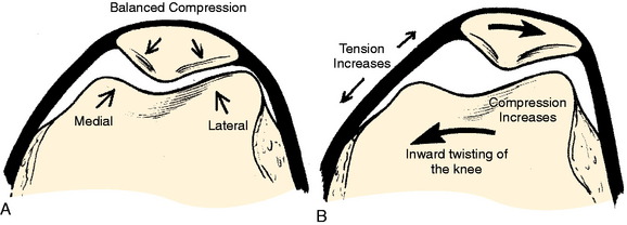
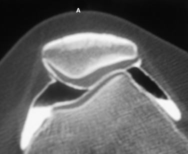
If these side-directed vectors exceed biologic tolerance, either instability or arthrosis may result. For example, an inward pointing of the knee increases the lateral direction of pull of the quadriceps. Therefore, the pull on the MPFL (and also medial retinaculum and medial meniscopatellar ligament) is increased and the direction of pressure on the patella is altered, creating an increase on the lateral facet and a decrease on the medial facet (Fig. 40-5). The radiographic appearance of subchondral density under the patellar facets is a useful clue to the mechanical environment (Fig. 40-6).
Maximum energy conservation during gait is due to precise anatomy and joint kinematics.34 Abnormalities in normal bony anatomy or joint motions distort the normal force vectors needed to transfer the body mass to the ground. Deviations in normal limb alignment may result in the knee joint flexion-extension axis advancing sideways while the body moves forward. These deviations include femoral anteversion or retroversion, excess internal or external tibial torsion, genu valgum or varus, hyperpronation, and Achilles contracture.
The foot progression angle (FPA) is generally defined as the angle between the long axis of the foot and the direction of body progression and averages 10° to 15°.28,37 It has been shown that the FPA remains similar despite differences in the torsion of the tibia or femur.37 It is likely that this is because proper ankle dorsiflexion cannot occur during gait if the ankle joint axis is not aligned with the direction of forward movement or because this presents the most stable position of the foot on the ground. Hip rotation must vary if the torsion of the long bones changes and the FPA stays constant. Alterations in both femoral and tibial torsion change the effective lever arm of the hip stabilizers1 and may account for the frequency of soft tissue complaints around the hip and pelvis, as well as the increased pelvic tilt and lumbar lordosis seen in these patients. Examples of the change in the position of the hip and knee with a constant foot progression angle and changes in femoral and tibial torsion are seen in Figures 40-7 to 40-11.
Figures 40-7 to 40-11 are drawn with an FPA of 13° (Seber average) for a normal male torsional alignment (Fig. 40-7), a normal female torsional alignment (Fig. 40-8), a female with 30° excess external tibial torsion (Fig. 40-9), a female with 30° excess femoral anteversion (Fig. 40-10), and a female with both 30° excess tibial external torsion and 30° excess femoral anteversion (Fig. 40-11). One may study the variations in knee joint progression with these common abnormal patterns. Yoshioka and associates47–49 found identical femoral anteversion in both males and females, equal genu valgus in both males and females, but an increase in external tibial torsion and in foot external rotation in females over males. This increase in external foot rotation may account for the apparent increased genu valgus in females, the increased incidence in PF symptoms in females, and even for the increased incidence of ACL tears in females.
BIOMECHANICAL EVIDENCE RELATING LIMB TORSION WITH PF INSTABILITY AND PAIN
A change in PF contact areas and pressures was noted after alteration of femoral or tibial torsion or rotation by Lee and coworkers22–24 Hefzy and associates,12 and van Kampen and Huiskes.45 Kiljowski and colleagues18 (unpublished data) placed lower limbs (femoral head to foot) in a frame with a clamp, attaching the femoral head to a vertical post that allowed the knee flexion to be altered by sliding the femoral head up and down the post. The foot was held in a position of normal FPA and an osteotomy was performed in the shaft of the femur, allowing rotation. PF contact pressures and MPFL strain were measured while the osteotomy changed the femoral torsion 15° and 30°, both inward and outward. At 30° knee flexion, lateral facet pressure increased an average of 30%, with a 30° increase in femoral anteversion, while medial facet pressures were decreased. Strain in the MPFL increased 57% after a 30° increase of internal femoral torsion. Fujikawa and coworkers11 in a biomechanical study that measured PF contact pressures concluded that if an angular deformity and a torsional deformity coexist, the rotatory component causes the greater PF changes. These authors also noted that when a varus deformity was created, the greater the varus deformity, the less the PF congruence.
CLINICAL EVIDENCE RELATING LIMB TORSION TO PF INSTABILITY AND PAIN
Brattström2 in 1964 measured trochlear depth in a group of patients with recurrent dislocation of the patella and confirmed that a shallow trochlea was always present. This author also defined the Q-angle and pointed out the change in Q-angle as a result of changes in limb rotation. He reviewed the literature on the rotational femoral osteotomy as described by Graser (1904), Fürmeier (1953), Kiesselbach (1956), and Vinditti and Forcella (1958) and concluded that the “femoral osteotomy is a big operation that demands prolonged after treatment. I have not encountered any instance of recurrent dislocation of the patella that justified my suggesting an operation of this nature to the patient.” Takai and associates41 measured femoral and tibial torsion in patients with unicompartmental arthrosis in either the medial, the lateral, or the PF compartment and found the highest correlation to be that of PF arthrosis with increased femoral anteversion (23° anteversion in the osteoarthritis group vs. 9° anteversion in the control group). Janssen16 found a high correlation between patellar dislocation and an increase in medial femoral torsion and speculated that this medial femoral torsion was also responsible for the development of trochlear dysplasia. Lerat and colleagues25,26 noted a significantly increased association of internal femoral torsion with both patellar instability (P < .0001) and patellar chondropathy (P < .001). Stroud and coworkers40 followed 92 patients who at age 5 showed 30° greater medial hip rotation (measured in extension) than lateral rotation. At age 24, PF pain was noted by 30% in the increased medial rotation group compared with only 8% in the control group (P < .001). Winson and associates46 found that 70% of adolescents undergoing arthroscopy for anterior knee pain had an increased internal torsion of the femur, compared with only 33% of those undergoing arthroscopy for a meniscal or cruciate injury. Turner44 noted increased external tibial torsion in patients with PF instability (25° vs. 19°). Of perhaps great significance to those who believe that muscle strengthening is the key to treating PF symptoms, Nyland and colleagues32 found a significant decrease in vastus medialis and gluteus medius electromyogram amplitude in athletes with clinically increased internal femoral torsion. Arnold and coworkers1 noted that an increase in femoral anteversion of 30° to 40° and decreased abduction moment arm strength of 40 to 50% was enough to impair normal walking, and therefore, those individuals required turning the knee inward to keep the hip from collapsing. This inward pointing of the knee creates high shearing force on the PF joint.
[/not-level-membership-for-orthopaedics-category]
