PACS Fundamentals
Objectives
On completion of this chapter, you should be able to:
• Define picture archiving and communication system (PACS).
• Compare and contrast the various types of PACS display workstations.
• Differentiate among the different types of digital imaging work flow.
• Define system architecture and recognize the three major models.
• Summarize the common functions found on a PACS workstation.
• Describe the situations and users that may require advanced PACS workstation functions.
Key Terms
Client/server-based system
Digital imaging and communications in medicine (DICOM)
Display workstation
Distributed or stand-alone system
File room workstation
Hanging protocol
Navigation functions
Picture archiving and communication system (PACS)
Quality control (QC) station
Reading station
Review workstation
Softcopy
Study
System architecture
Web-based system
Workflow
The picture archiving and communication system (PACS) is becoming more commonplace in today’s hospitals because hospital administrators have come to see the necessity of having such a system to serve physicians and patients even though it is expensive. The initial capital cost is great, but the benefit of having the system far outweighs the cost. This chapter outlines the basic concept of a PACS and its components, describes common PACS architecture, and gives examples of typical PACS work flows that may be seen in a hospital.
Fundamentals
As discussed in Chapter 1, a PACS consists of digital acquisition, display workstations, and storage devices interconnected through an intricate network (Figure 9-1). The PACS is an electronic version of the radiologist reading room and the file room. The first PACSs were used in the early 1980s and generally served a single modality. Large research institutions housed early systems because most were developed by the scientists who worked at those institutions. As vendors became more involved, they developed proprietary systems that were very specific to their modalities. Finally, as physicians and hospitals became interested, it was determined that there must be standardization.
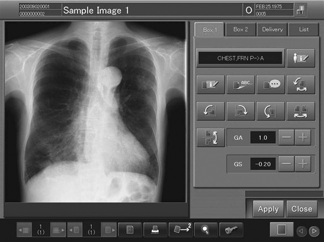
Digital imaging and communications in medicine (DICOM) is a universally accepted standard for exchanging medical images among the modality, viewing stations, and the archive. First completed in 1985, this standard laid the groundwork for the future development of integrated PACSs. Now each modality and PACS communicates via DICOM, and DICOM continues to be refined every year. Every vendor and modality boasts DICOM compatibility (Figure 9-2), but each DICOM statement must be read carefully to determine the extent of the compatibility. DICOM compatibility issues are outside of the scope of this textbook.
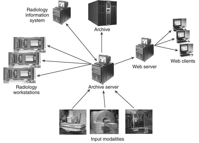
To understand what a PACS is and how it is used, it helps to look at the system’s individual parts. The following sections break down a PACS into its three fundamental parts (Figure 9-3): image acquisition, display workstations, and archive servers. Each of these topics is covered in depth in other chapters of the book.
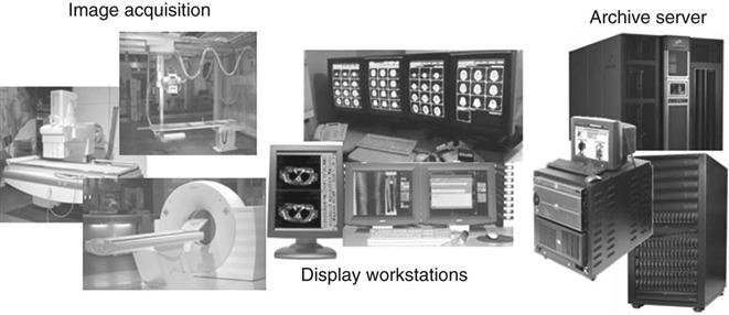
Image Acquisition
In modern radiology departments, most images are acquired in a digital format, meaning that the images are inherently digital and can be transferred via a computer network. Ultrasound, computed tomography (CT), magnetic resonance imaging (MRI), and nuclear medicine have been digital for many years and have been taking advantage of PACS far longer than general radiography has. As stated earlier, the first PACS served a single modality, namely, ultrasound. Ultrasound mini-PACS networks were the norm in many hospitals. Radiologists routinely made diagnoses by looking at images on the modality’s computer screen. It was a natural step from there to convert ultrasound to softcopy reporting (i.e., reading images on the computer without hardcopy films).
As the CT and MRI image sets became larger because of the increased number of cross-sectional images per patient, radiologists routinely went to the modality to view the images. This slowed down the scanning process for the technologists, and vendors began getting requests for extra console stations for radiologist viewing. These workstations were directly connected to the modalities. Radiologists could view the large stacks of images and perform simple image manipulation. These workstations morphed into mini-PACS and eventually into full-blown systems for CT and MRI. As discussed in Chapters 4 through 7, general radiography has taken the digital leap with digital projection radiography. Now the conversion to a completely digital radiology department is a reality.
Display Workstations
A display workstation is any computer that a health care worker uses to view a digital image (Figure 9-4). It is the most interactive part of a PACS, and these workstations are used inside and outside of radiology. The display station receives images from the archive or from the various radiology modalities and presents them for viewing. The display workstation has PACS application software that allows the user to perform minor image-manipulation techniques to optimize the image being viewed. Some display stations have advanced software to perform more complex image-manipulation techniques. More details about display workstations are given later in the chapter.
Archive Servers
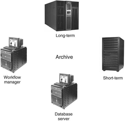
An archive server is the file room of the PACS. It is composed of a database server or image manager, short-term and long-term storage, and a computer that controls the PACS workflow, known as a workflow manager (Figure 9-5). The archive is the central part of the PACS and houses all of the historic data along with the current data being generated. In many institutions the archive serves as the central hub that receives all images before they are released to the radiologists for interpretation. The archive and all of its components are studied in depth in Chapter 10.
Workflow
Workflow is a term that can be used in any industry or in any organization. It simply means how a process is done, step by step. In radiology, the term workflow has always been used to describe how an examination is completed, from order entry to transcribed report. This section describes a generic film-based workflow and then compares it with a generic PACS workflow. The workflow in each radiology department is different because there are many variables.
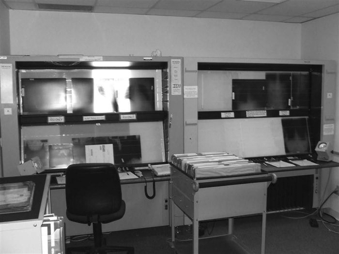
Film-Based Workflow.
Most departments were designed years ago for film and chemical processing. Pass boxes were built into walls that fed into darkrooms and into large open reading rooms that had gigantic multiviewer lightboxes lining the walls (see Figure 9-11). Eventually chemical-processing time decreased from a few minutes to less than 60 seconds in some cases. As film and processing technology advanced, workflow became more efficient, despite the fact that technologists still have to hand-deliver film to radiologists and make the occasional copy for a referring physician.
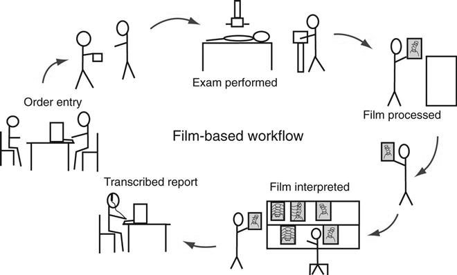
The following list outlines a typical workflow in a radiology department, from entering the order to transcribing the report (Figure 9-6).
• The first step in any radiology department workflow is the entry of the order. The order may be a paper prescription from the ordering doctor, or the order may have been placed in the computer system by any hospital staff member. Either way, an order is placed in the radiology information system (RIS), and a requisition is generated. A requisition generally contains the following information:
• Patient’s hospital identification (ID) number
• The paper requisition is then passed on to the technologist who will be performing the examination.
• The technologist prepares the room for the patient and brings the patient back to the room.
• The technologist critiques each film and repeats exposures as necessary.
• The technologist makes copies if necessary and releases the patient with the copies.
• The radiologist reads the films and dictates a report into the dictation system.
Generic PACS Workflow.
The PACS workflow is in many ways different from the film-based workflow (Figure 9-7). The technologist may get the order via an electronic worklist or a paper requisition, but after that, the process begins to change.
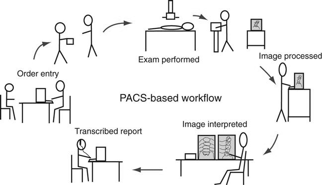
With PACS it is possible that the time it takes from performing the examination to completing the final radiologist’s report is only a couple of hours, compared with a couple of days for the film-based workflow.
System Architecture
System architecture can be defined as the hardware and software infrastructure of a computer system. In a PACS, the system architecture normally consists of acquisition devices, storage, display workstations, and an image management system. The following discussion outlines three common PACS architectures and takes a look at the flow of images after acquisition.
Client/Server-Based Systems
In a client/server-based system, images are sent directly to the archive server after acquisition and are centrally located (Figure 9-8). The display workstation functions as a client of the archive server and accesses images based on a centralized worklist that is generated at the archive server. The health care worker at the display workstation chooses a name from the central list, and the archive server sends the image data to the display station. After the “client” is finished, the image data are flushed from its memory. Most systems allow basic image manipulation at the display workstation or “client,” and the changes are saved on the archive server.
Advantages
Disadvantages
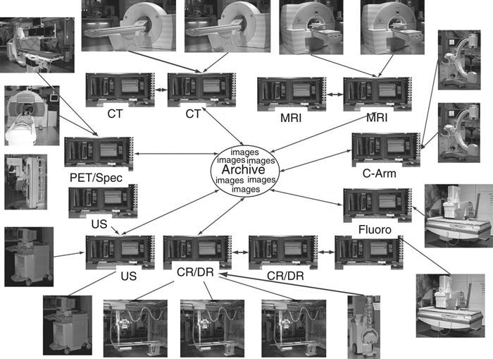
Distributed Systems
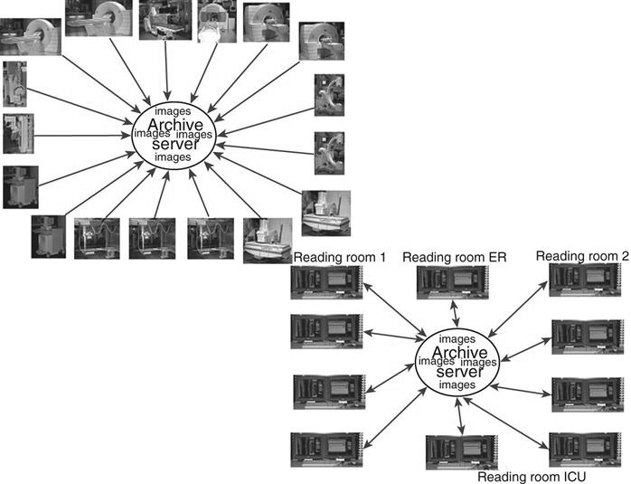
In a distributed or stand-alone system, the acquisition modalities send the images to a designated reading station and possibly to review stations, depending on where the order originated (i.e., the intensive care unit or the emergency room) (Figure 9-9). In some systems, the images are sent from the modality to the archive server, and the archive server distributes the images to the designated workstation. The reading station designations may be designed based on radiologist reading preferences. For example, MRI may be sent to one station and CT to another, or all cross-sectional neurologic images may be sent to one station, but all body images are sent to another. The designation is decided after extensive workflow observation. Moreover, in a distributed model, the workstations can query and retrieve images from the archive. All images are then stored locally and subsequently sent to the archive server after they have been read. These images remain on the local hard drive of the workstation until they are deleted either by a user or at a predetermined time set by system rules.
Advantages
Disadvantages
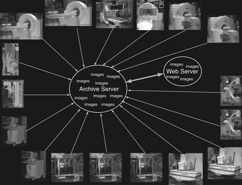
Web-Based Systems
A web-based system is very similar to a client/server system in how data flow. The significant difference is that both the images and the application software for the client display are held centrally (Figure 9-10). This means that when someone wants to view images from a web-based application, he or she simply searches for the pertinent images and the web browser will display the images that are held in the web server. This does not require special software to be downloaded to the computer. In a client/server system, the application software is locally loaded to the client, and only the images are held at the archive.
Advantages
Disadvantages
Display Workstations
The display workstation is the most interactive part of a PACS, consisting of a monitor and a computer with a mouse and keyboard. In addition, each system has hardware and software that fits the users’ requirements.
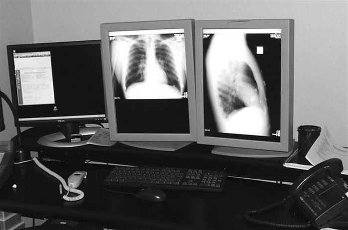
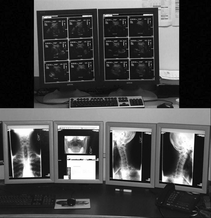
As the technologist knows, conventional film/screen radiography uses large multiviewer lightboxes to display the images (Figure 9-11). Early in the history of PACSs, radiologists believed that they needed four to six monitors to match the viewing capability they had with the lightboxes. As the radiologists have become more comfortable viewing images on monitors, the number of monitors required by the radiologists has decreased to an average of two (Figure 9-12). This decrease can also be attributed in part to the continued development of viewing software and better hardware, namely, mice.
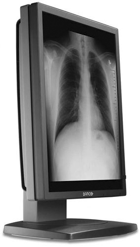
The monitor is one of the most important elements of a PACS display station. The cathode ray tube (CRT) (Figure 9-13) and the liquid crystal display (LCD) (Figure 9-14) are the most popular types of monitors in a radiology department. The LCD has decreased in price and increased in quality and has taken over the entire PACS display market because of its size, resolution, and lack of heat production. The LCD also requires less maintenance, gives out more light, and can be used in areas with a high amount of ambient light. In early PACS reading rooms, supplemental air conditioning had to be installed to offset the heat put out by multiple CRTs. Along with the number of monitors used, the resolution and orientation of the monitor are also factors in determining which type of monitor to buy for each workstation. Most cross-sectional imaging is read on a 1K square monitor (Figure 9-15), and most digital projection images are read on at least a 2K portrait monitor (Figure 9-16).
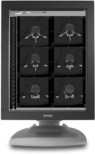
Remember from Chapter 2 that a basic picture element on a display is known as a pixel. The number of pixels contained on a display is known as its resolution. The relationship between pixels and resolution can be stated as follows: the more pixels in an image, the higher the resolution of the image, and the more information that can be displayed. Resolution can also be defined as the process or capability of distinguishing between individual parts of an image that are adjacent. Pixels are arranged in a matrix. A matrix is a rectangular or square table of numbers that represents the pixel intensity to be displayed on the monitor. Common screen resolutions that are found on today’s monitors are 1280 × 1024 (1K), 1600 × 1200 (2K), 2048 × 1536 (3K), and 2048 × 2560 (5K).
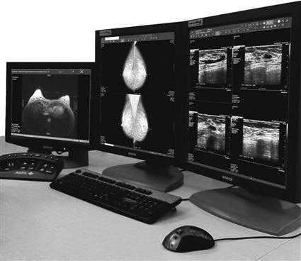
Medical display monitors are generally of a higher quality than display monitors used for other applications. Radiologists often use the highest resolution monitors available for the modality that is being read. For example, mammography requires a 5K or 5-megapixel resolution to provide the viewing capacity needed, but a cross-sectional image requires only a 1K monitor to view the necessary information. Because a referring physician is not the primary doctor reading the examinations, a 1K monitor would be sufficient for his or her viewing needs.
Display stations can be categorized by their primary use: primary reading stations for radiologists, review stations for referring physicians, technologist quality control (QC) stations where technologists review images, and image management stations for the file room personnel. Each of these workstations has one specific main purpose and is strategically located near the end user of its designated purpose.
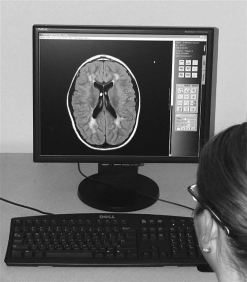
Radiologist Reading Stations
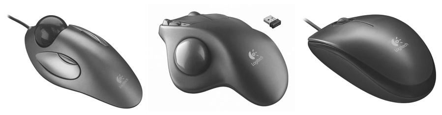
The radiologist reading station (Figure 9-17) is used by a radiologist when making a primary diagnosis. The reading station has the highest quality hardware, including the best monitor. The computer hardware meets the needs of the PACS vendor, but it will usually be very robust, requiring little downtime. The keyboard and mouse can be customized. There are many different styles of mice available that can increase the efficiency of the software being used (Figure 9-18).
There is generally access to a nearby RIS, with a dictation system near or even connected to the PACS station. Many PACSs have software that integrates the RIS and dictation system.
Physician Review Stations
The physician review workstation (Figure 9-19) is a step-down model of the radiologist reading station. Many vendors use the same level of software but may eliminate some of the more advanced functions. One of the most important features on a physician review station is the ability to view current and previous reports along with the images. This can be accomplished with the integration of RIS functions with the PACS software mentioned above. Most referring physicians want to read the radiologist’s report along with seeing the patient’s images, and often the report is more important to them than the images.
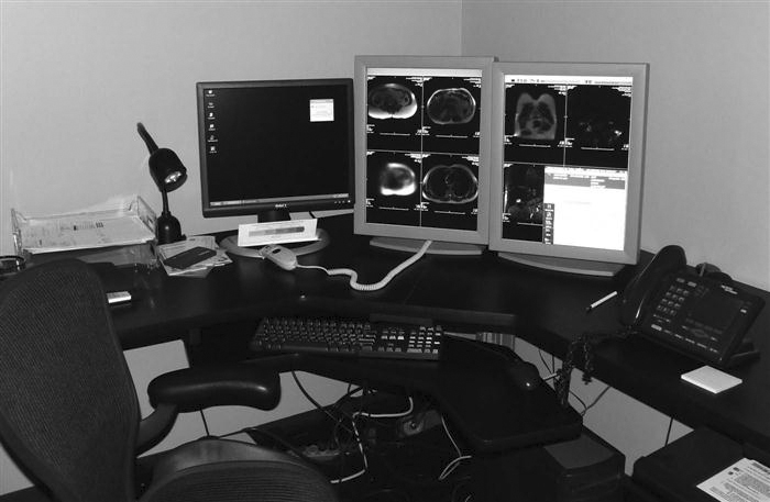
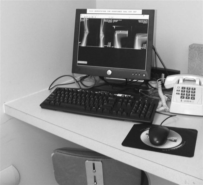
The software may either be loaded on a stand-alone station that is dedicated to viewing images, or it may be delivered over a web browser on any personal computer (PC) within an office or on a floor. In high-volume areas such as the emergency room and the intensive care unit, there are dedicated PACS workstations for image viewing (Figure 9-20). These dedicated stations may have the higher-end monitors such as the radiologist reading stations, but many may have lower-end monitors because of cost constraints.
One of the greatest advantages of a PACS is the ability to view the same set of images in multiple locations at one time. In the film/screen era, referring physicians would make the trek to the radiology department to consult with a radiologist about a patient’s image, hoping that the films would be found in the file room and that the radiologist was available to consult. Now with PACS, the referring physician can pull up the patient’s images in his or her office and read the radiologist’s report. The referring physician and the radiologist can consult on the telephone while looking at the images simultaneously. This is one way that PACSs have improved continuity and speed of patient care.
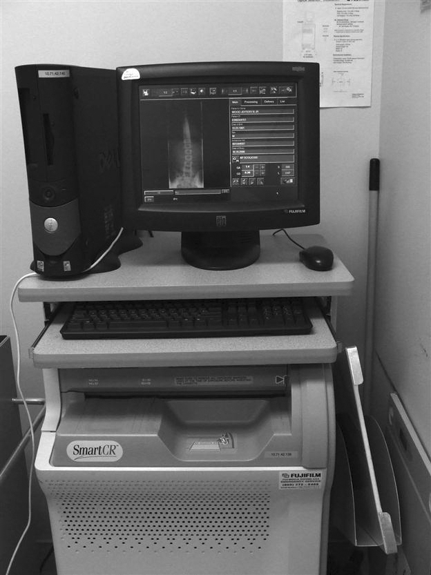
Technologist QC Stations
The technologist quality control (QC) station (Figure 9-21) is used to review images after acquisition but before sending them to the radiologist. The QC station may be used to improve or adjust image quality characteristics, or it may be used to verify patient demographic information. Many QC stations are placed between the computed radiography (CR) and digital radiography (DR) acquisition modalities as a pass-through to ensure that the images have met the departmental quality standard. The technologist QC station generally has a 1K monitor. When manipulating images, the technologist must be careful not to change the appearance too much from the original acquired image. The technologist should consult frequently with the radiologist to ensure that the images being sent are of the required quality.
The QC workstation can also be used to query and retrieve historic images before beginning of an examination so that the technologist can check previous pathology or body characteristics. This can help with the selection of technical factors or procedural protocol. It is common protocol in a film-based department to pull film jackets on patients before performing an examination. The QC station affords the same benefit as pulling the film jacket.
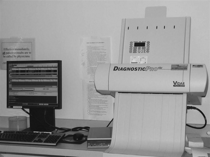
File Room/Image Management Stations
The file room in a radiology department has seen many changes over the years. Before PACS, the file room was a large open room with endless rows of shelves full of film jackets. Today a file room in a PACS environment may be as simple as a couple of computers with CD/DVD burners and a dry laser to make copies for outside needs.
The file room workstation (Figure 9-22) may be used to look up examinations for a physician or to print copies of images for the patient to take to an outside physician. Many hospitals are moving away from printing films to save the cost of the film and are instead moving toward burning CDs with the patient’s images because they are less expensive. The CD of images can be viewed on any PC and generally comes with easy-to-use software burned onto it with the images.
The file room personnel may also be responsible for correcting patient demographics. If images with incorrect demographics are sent to the archive, then it is difficult to pull those images the next time the patient comes in for an examination. The archive is a database and is only as good as the information that is put into it.
Common Functions
This section provides an overview of common functions found on a PACS workstation. All of the functions should be available on any level of the workstation except for the advanced functions, which are specific to different types of workstations. The functions can be broken down into four categories: navigation functions, image manipulation and enhancement functions, image management functions, and advanced workstation functions.
Navigation Functions.
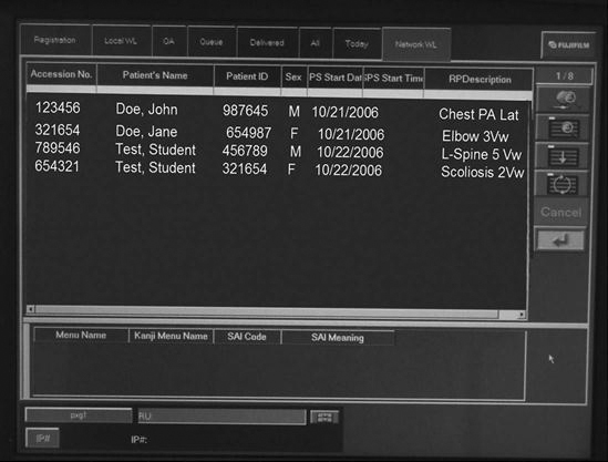
Navigation functions (Figure 9-23) are used to move through images, series, studies, and patients. The worklist is used to navigate through patients. Most worklists are customizable for the user. One doctor may want to see only unread CT studies, and another may want to see all neurologic studies done that day regardless of the modality. Most modern PACS software conforms to the Windows (Microsoft, Redmond, WA) look and feel. The use of grab bars on the right side of Windows to scroll through a list and the activation of the scroll wheel on the mouse to scroll through the list are common features. The mouse is also a very useful navigation tool. The right mouse offers many short-cut features in a menu of frequently used tasks and applications.
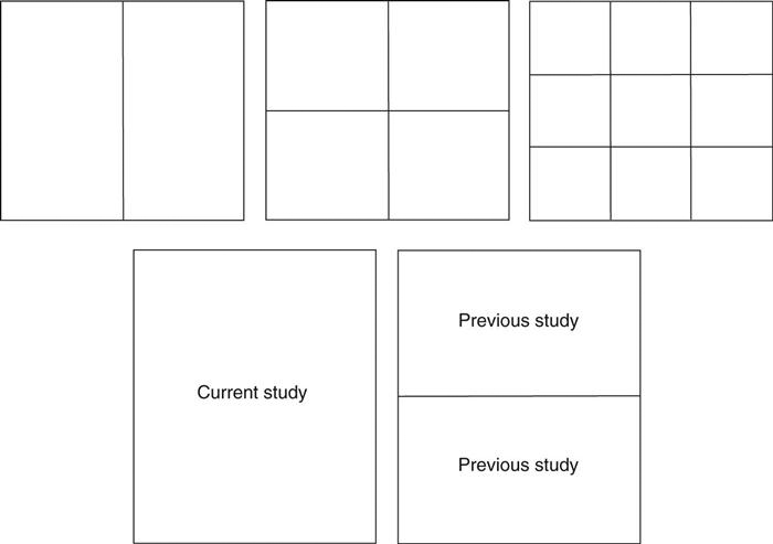
Hanging Protocols.
Once a patient has been selected from the worklist, the images load into the display software. In most PACSs, each user has the ability to set up custom hanging protocols. A hanging protocol (Figure 9-24) is how a set of images will be displayed on the monitor. Users can choose the hanging protocols they prefer for each modality. The hanging protocols can also be required to show the previous examination on one monitor and the current examination on the other. Once the hanging protocols have been set, the most efficient study navigation is determined.
Study Navigation.
A study in PACS is the current or previous examination being viewed. A study may comprise two or three single images, as is the case with projection radiography, or it may contain several series of images, as is the case with MRI. The images can be paged through either with the scroll wheel or with arrows on the keyboard, or they can be run through in stacks. Many vendors call the stack mode of scrolling through images cine. The cine function is used most often in sectional imaging.
Many vendors provide icons (pictures within the software that activate software functions) that allow the user to move among a patient’s various studies or open the next unread patient in the worklist after having read the current study. Another navigation tool that is commonly found is a close patient or close study icon. This icon closes the active patient or study and either pulls up the worklist or moves to the next unread patient in the worklist. Users can set up these tools according to their preferences.
Image Manipulation and Enhancement Functions.
Once an image has been opened on the display, there are many tools that can be used to change the appearance of the image. Here is a bulleted list of some of the most commonly used functions:
• Window width/window level (Figure 9-25): This is usually a default function of the left mouse button or middle scroll wheel when an image is actively displayed in the software. By depressing and holding down the mouse button and moving the mouse up and down and left and right, the window width and window level can be adjusted. The window width represents the range of gray values that are being viewed, and the window level represents the brightness.
• Annotations (Figure 9-26): Most PACSs can annotate text or graphics onto the image. This function should not be used to label left or right to indicate the patient’s side; digital R and L will not hold up in court because of the ability to mark anywhere on the image and flip and rotate the image into any layout on the screen. Annotations can indicate prone or supine, 30 minutes, upright or flat, or any other image information the department deems appropriate. Radiologists frequently place arrows or circles around pathology or questionable areas so that the referring physician can pinpoint what is in question.
• Flip and rotate (Figure 9-27): These functions are used to orient the image in the anatomic hanging position desired by the department. There are usually left-to-right flip and 90-degree clockwise and counterclockwise icons. This function makes it very important that lead markers are used to ensure that the radiologist reads the correct side.
• Pan, zoom, and magnify (Figure 9-28): These functions are used primarily by the radiologist to increase the size of an area on the image. The magnify function will usually enlarge a square area of the image, and the square can be moved around the image to quickly see various areas enlarged. The pan and zoom functions are usually used together. The image is first zoomed up to the desired magnified level, and then the pan icon is activated so that the zoomed image can be moved around, allowing the user to view the different areas of the image.
• Measurements (Figure 9-29): Various measurement functions are found on a PACS station. The most common is the distance measurement. The size of a pixel is a known measurement, so the software can measure structures on the image based on this known measurement. Another common measurement is the angle measurement, which measures the angle between two structures; this measurement function is commonly used when reading spine studies. Another common measurement a radiologist may use is a region of interest (ROI), which will determine the pixel intensity of a certain area. Because each type of tissue or fluid has a little bit different intensity reading, the radiologist can make a determination whether something is solid or fluid.
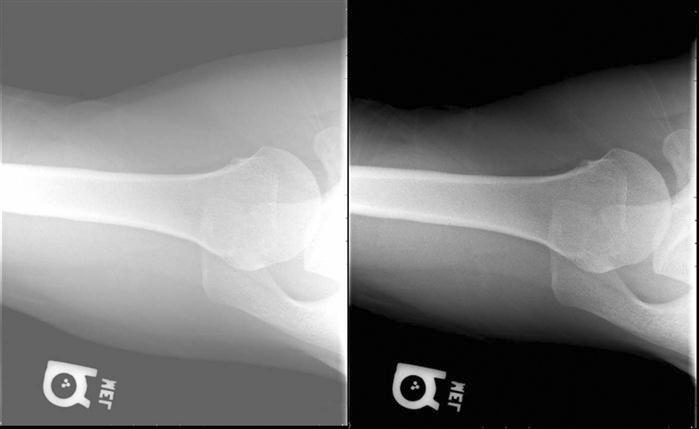
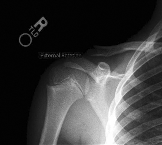
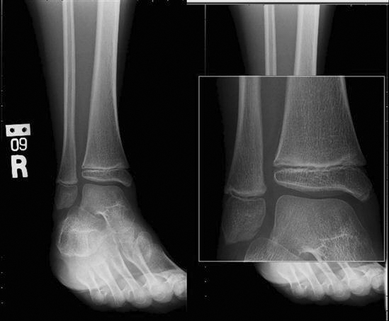
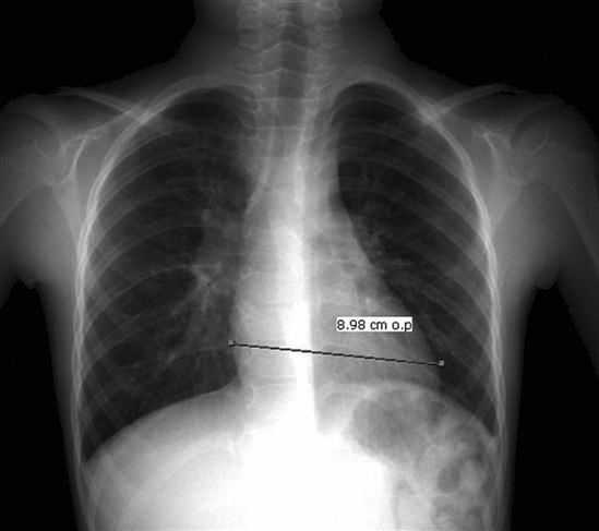
Image Management Functions.
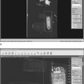
Most PACSs allow the user to modify patient demographics (Figure 9-30) at the technologist QC station, the reading station, and the file room station. It is imperative that the patient demographics are correct. If wrong information is archived on an image, the image will be difficult to retrieve and may never be found again. Make changes only when the information is absolutely known to be wrong. To minimize errors, many hospitals allow only certain people the access to change demographics.
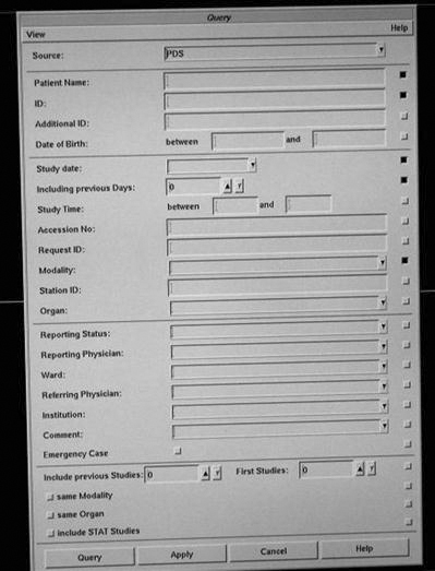
Another image management function is the query/retrieve function used to retrieve studies from the archive (Figure 9-31). The query function allows the user to query a study on multiple fields such as the patient’s name or ID, date of service, or modality. Some systems also allow a query based on a diagnosis code or comment field.
Many vendors have provided a CD-burning option that allows users to save studies to a CD for outside use. The feature may be available only in the file room to control the CDs that are sent out. Health Insurance Portability and Accountability Act (HIPAA) compliance must also be maintained. Another common feature is the ability to copy and paste images into a document. This is frequently used with the web-based systems when creating presentations for conferences. The patient information must be removed from the image before it is placed into a presentation.
Some hospitals have retained the ability to print films for outside use. This is also usually done only in the file room so that control can be maintained over the printed films for HIPAA purposes and cost reasons. Some hospitals have also connected workstations to paper printers for quick consults and medical records.
Advanced Workstation Functions
Advanced functions are usually placed on specialty workstations for the radiologist, but some are found on the technologist QC station to further enhance the images. The following are some of the most common advanced functions.
Reading Station Advanced Functions
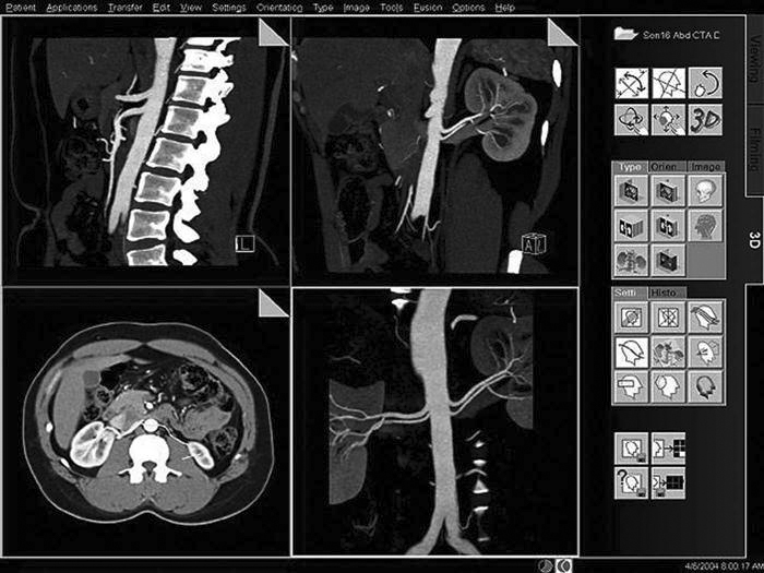
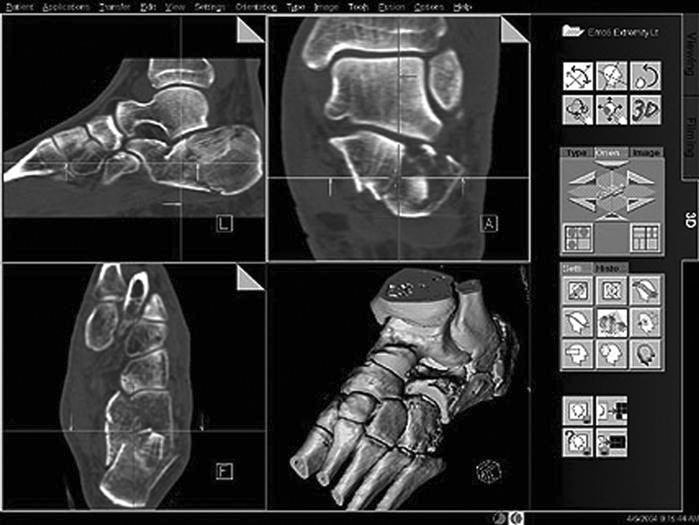
• Multiplanar reconstruction (MPR) (Figure 9-32): One of the most commonly used three-dimensional (3D) rendering techniques. When doing a CT scan of a patient, thin axial slices can be acquired of a volume of tissue. The slices can then be loaded into the MPR software, and a reconstruction in another plane can be produced. The most common application is producing coronal images from the axial set to reduce radiation to the patient and to reduce scan time at the modality.
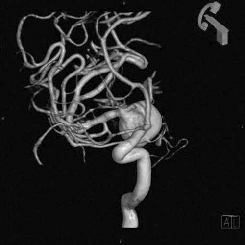
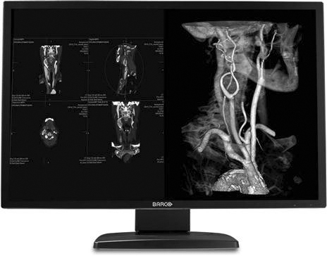
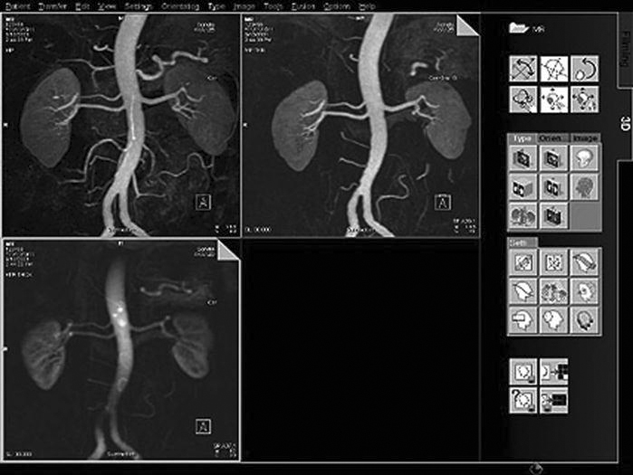
• Maximum intensity projection and minimum intensity projection (MIP and MinIp) (Figure 9-33): Used to visualize vessels (MIP) and air-filled structures (MinIp). Commonly performed after the injection of contrast on CT and MRI studies, the contrast will show areas of strictures and blockages within the vessels.
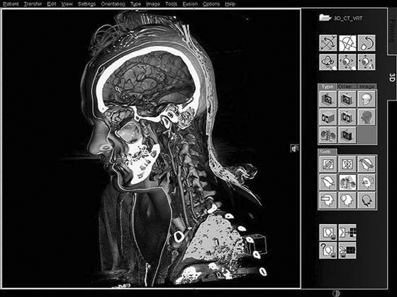
• Volume rendering technique (VRT) (Figure 9-34): Similar to MIP but allows the user to assign colors based on the intensity of the tissue so that bone, contrast agent, and organs can be seen in different colors. The technique uses a histogram-type graph to differentiate the various structures.
• Shaded surface display (SSD) (Figure 9-35): Using a threshold of pixel intensity values, everything below the threshold will be removed, and everything above will be assigned a color and shown as a 3D object.
Technologist QC Station Advanced Functions
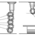
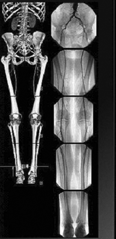
• Stitching (Figure 9-36): Used when multiple images need to be put together into one image. The most common application is for full-spine x-rays or a scoliosis series. The examination was traditionally performed on a 3-foot film and processed; manufacturers have developed a 3-foot cassette that contains multiple imaging plates (IPs). Each of the IPs is scanned through the reader, and the individual images are sent to the QC workstation. The software then interpolates the images and connects them using known markers from the IPs. The technologist can adjust how the images are connected. Another application of stitching is producing long leg images for leg length discrepancy studies. The images are acquired in a fashion similar to the one described above and stitched together. If the special 3-foot cassettes are not available, a radiopaque ruler must be used to ensure that the images are stitched at the right area.
There are many other advanced workstation functions available to be added to the PACS workstation. This is a growing field with advancements coming each year. Specific information about how to perform these procedures can be found in the vendor’s user manual.