PACS Archiving and Peripherals
Objectives
On completion of this chapter, you should be able to:
• Describe the use of an image archive in terms of short- and long-term storage.
• Explain the function of the image manager.
• Define the concept of an application service provider.
• Compare and contrast dry laser imager technology with wet laser imager technology.
Key Terms
Application service provider (ASP)
Archive
Archive server
Burner
Digital versatile disk (DVD)
Disaster recovery
Dry imager
Film digitizer
Image manager
Image storage
Magnetic disk storage
Magneto-optical disk (MOD)
Redundant array of independent (inexpensive) disks (RAID)
Tape
Teleradiology
Tier
Ultra density optical (UDO) disk
Wet imager
Archiving Components
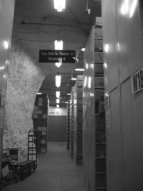
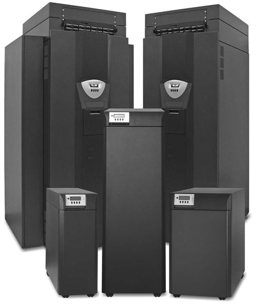
The term archive can be defined as a place where records or documents are preserved (Figure 10-1). In a picture archiving and communication system (PACS), the electronic archive serves as the new file room and warehouse for all digital imaging and communications in medicine (DICOM) imaging modalities (Figure 10-2). The PACS archive stores all patient and image data, often on magnetic tape or optical disk. Also, the PACS archive controls the receipt, storage, and distribution of new and historic images. Because of the explosive growth in the use of digital imaging in radiology, the archive is one of the fastest growing components in the PACS. Archive technology continues to make drastic improvements each year; the storage capacity is said to double every 18 to 24 months, and the price per gigabyte also continues to decrease.
The archive is a complex arrangement of computers and storage space. As a whole, it consists of several components, both hardware and software. These can be divided into two major categories: image manager or controller and image storage or archive server. The next two sections discuss image management and image storage. Various types of image storage hardware are described. The chapter ends with a discussion of things to consider when choosing an archiving system.
Image Manager
The image manager contains the master database of everything that is in the archive. It controls the receipt, retrieval, and distribution of the images it stores and also controls all the DICOM processes running within the archive.
The image manager generally runs a reliable commercial database such as Sybase (Sybase Inc., Dublin, CA) or Oracle (Oracle Corp., Redwood Shores, CA) with structured query language (SQL). This database contains only the image header information, not the image data. The image data are stored on the archive server, which is discussed in the next section. The database is mirrored, meaning that there are two identical databases running simultaneously so that if one goes down, the system can call on the mirror and continue to run as normal, a very important feature.
The image manager is also the PACS component that interfaces with the radiology information system (RIS) and the hospital information system (HIS). This allows the PACS database to collect additional patient information that is necessary for its effective operation. Information extracted from these databases will be used in the prefetching and routing of images to various locations throughout the PACS. The image manager can also play a key role in populating image information into the hospital electronic medical record (EMR).
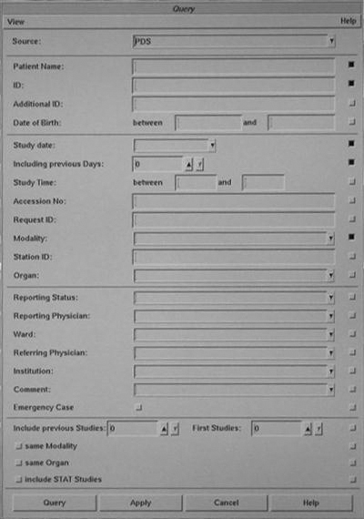
As mentioned earlier, the image manager database contains the DICOM header information, such as the patient name, identification information (ID), examination date, ordering physician, and location. These fields are organized within the database so that when someone queries for a study on a workstation, the image manager can quickly move through these data fields and locate the images that are being queried (Figure 10-3). The database has pointers associated with each image on the archive server that point back to the data fields within the database. The following list summarizes the process:
Image Storage
The image storage or archive server consists of the physical storage device of the archive system. It commonly consists of two or three tiers of storage. A tier is a level, layer, or division of something. In an archive server, a tier represents a specific level of archive: short-term, mid-term, or long-term. Most PACS archive systems are set up with a short-term tier and a long-term tier. Short-term means being online or available very quickly, usually within 3 to 5 seconds. Long-term means near line, or images that must be retrieved from a tape or disk storage device and brought to a redundant array of independent (inexpensive) disks (RAID). This could take 1 to 5 minutes.
Short-Term Storage.
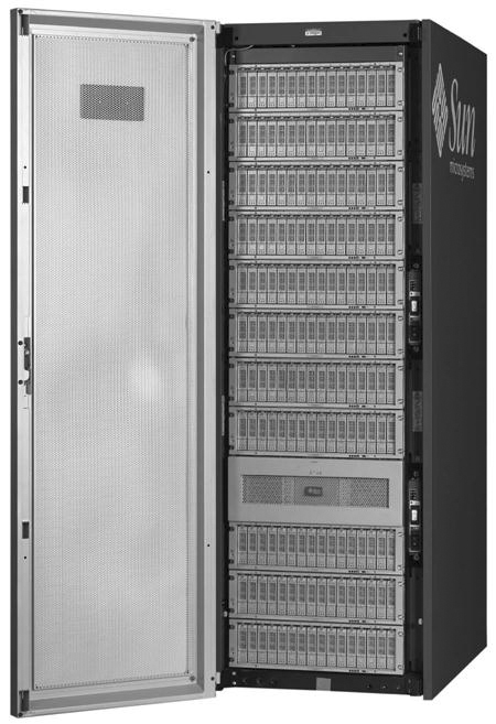
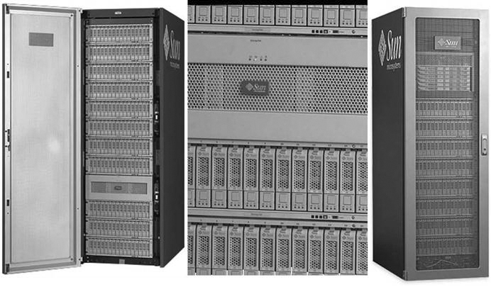
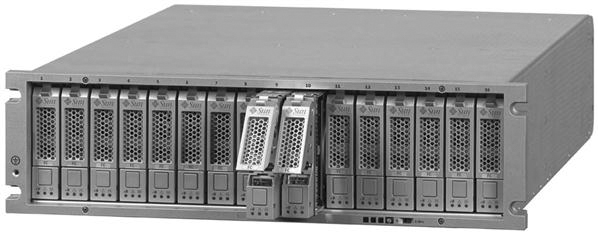
The short-term tier is commonly a RAID (Figure 10-4). A RAID is composed of several magnetic disks or hard drives that are linked together in an array (Figure 10-5). The size of the RAID ranges from several hundred gigabytes to several terabytes. As the individual disk sizes continue to increase, so does the potential size of the RAID.
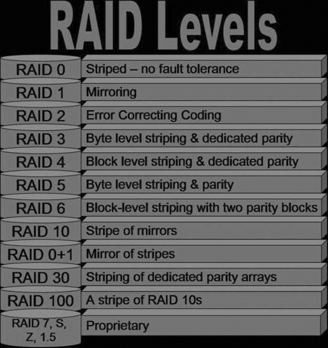
In 1988 David Patterson, Garth Gibson, and Randy Katz coined the term RAID in an article entitled “A Case for Redundant Arrays of Inexpensive Disks (RAID).” Their presentation introduced 5 levels of RAID; now there are 11 levels (Figure 10-6), most of which are combinations of the first 5. The following discussion, which includes diagrams and a short synopsis for each of the RAID levels 0, 1, 3, and 5, illustrates how the RAID levels differ from one another:
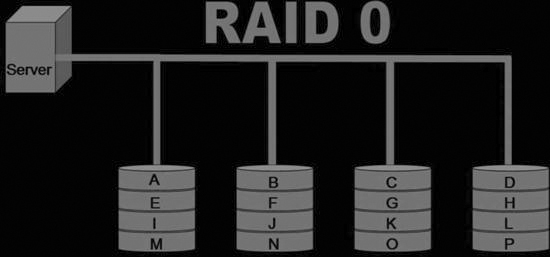
• RAID 0: Data are “striped” across all of the connected disks. Striping means that the data are broken up into pieces, and each disk will have one piece of the data (Figure 10-7). When the data are called up from the RAID, all of the data are put together from the disks and presented to the user as a whole.
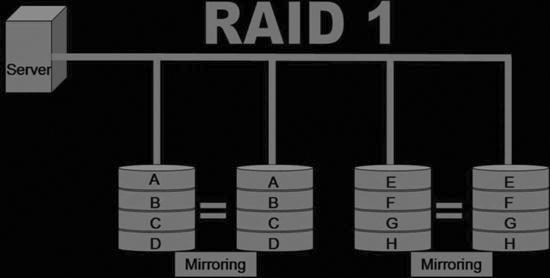
• RAID 1: All of the data sent to the RAID are mirrored onto two disks (Figure 10-8). Mirroring means that all of the data are duplicated and placed onto two separate disks. This RAID level has full redundancy, meaning that if one disk goes down, the other one takes over and operation of the system continues. This is a very expensive system because only half of the total storage is used.
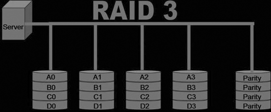
• RAID 3: The data are striped across all of the disks just like in RAID 0, but there is one disk that is set aside for error correction. This disk is known as the parity disk (Figure 10-9). This RAID level is rarely used.
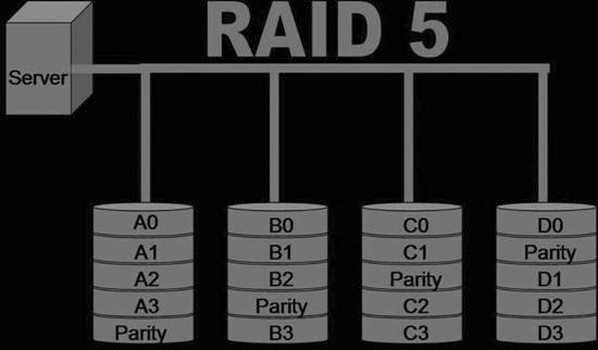
• RAID 5: This RAID level is similar to RAID 3 but instead of having the parity written to one disk, it is striped along all of the disks within the RAID (Figure 10-10). RAID 5 is the most common level used for a PACS archive because it provides adequate redundancy and fault tolerance.
The striping of data increases the reliability and performance of the system. With certain levels of RAID, if one disk fails, the data from that disk can be regenerated using the redundancy of data on the other disks. The error correction detects any transmission errors, and the data will also be regenerated based on the information from the other disks. Striping also enhances performance because if all of the data were on one disk, data added to the disk first would be accessed first, requiring longer wait times for data added to the disk later. Spreading data over several disks allows all data to be accessed at the same time.
Long-Term Storage.
Because RAID is becoming more cost-effective, many hospitals use RAID storage for both their short-term and their long-term archive. Other long-term storage products that are still widely used are optical disk, tape, and magnetic disk. Optical disk and magnetic tape archive solutions use a jukebox (Figure 10-11) to hold the tapes or disks; the magnetic disk uses an array. The jukebox has controller software that interfaces with the image manager to keep track of exactly where each image is located. The jukebox controller keeps similar studies together as much as possible to minimize access time. The long-term archive has much higher access times than the short-term archive, but the price of storage per gigabyte is much less with the jukeboxes.
Optical Disk
Magneto-optical Disk.
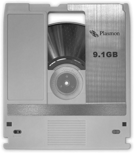
A magneto-optical disk (MOD) (Figure 10-12) is very similar to a compact disk (CD) or digital versatile disk (DVD) in that it is read optically with a laser, but the disk itself is housed within a plastic cartridge. MODs tend to be more reliable than some of the other long-term storage options. The disks are rather robust and can withstand many years of reading. They can be read faster than some of their counterparts. The cost per gigabyte is a bit higher for MODs than for some of the other long-term storage options, but MODs are still a viable long-term storage option.
Digital Versatile Disk.
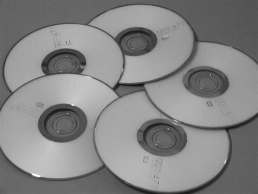
Digital versatile disks (DVDs) (Figure 10-13) were first introduced for use in video. CDs were used by a few early PACS adopters, but users found that the CDs could not hold enough data to make a CD archive cost and space efficient. DVDs have a much higher capacity. In 2006, a double-sided, two-layered DVD held 17 GB of data, whereas a CD held 650 MB. DVDs are the least expensive method for long-term archiving per gigabyte.
Ultra Density Optical.
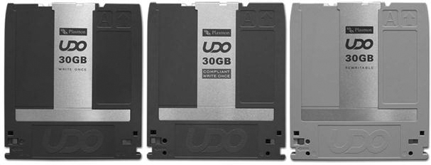
Ultra density optical (UDO) disk (Figure 10-14) is the new-generation MOD. A UDO disk uses blue laser technology in its read and write activities. Plasmon (Plasmon PLC, Hertfordshire, UK) introduced the first UDO disk in 2004 with a disk capacity of 30 GB (2006 MOD technology was at 9.1 GB), and the capacity is predicted to increase to 60 GB and then to 120 GB to accommodate industry needs. Currently, UDO technology operating costs are less than MODs and very competitive with DVD technology. The tape libraries being offered in 2006 held between 24 and 638 disks.
Tape.
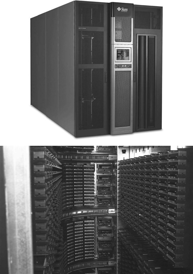
Tape (Figure 10-15) libraries provide the greatest scalability of the long-term archive options. These libraries can grow to hundreds of terabytes, possibly even a petabyte, and this technology will continue to improve and expand its storage limits. Tape is a fairly low-cost archive medium that comes in various sizes. These tapes are contained within a jukebox or library that has multiple drives and a robot arm to move the tapes in and out of the drives. These libraries can hold between 10 and 1448 tapes in one library (Figure 10-16). Most of the libraries are scalable, meaning that additional libraries can be added to the original.
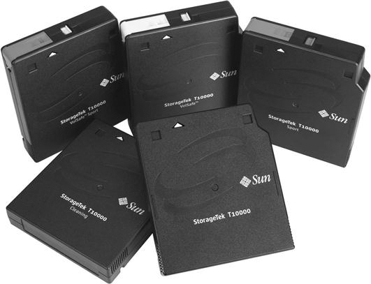
One of the biggest disadvantages of tape is its unreliability over multiple uses. The tape can wear after several years of heavy use and may become damaged. Tape also has a longer access time than its optical counterparts. Tape has greatly improved in its speed and reliability, and it will continue to be a factor in long-term PACS archiving systems.
There are several types of magnetic tape technologies available:
Magnetic Disk.
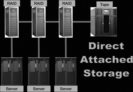
As mentioned earlier in the chapter, as the price of magnetic disk storage (Figure 10-17) continues to decrease, RAID storage becomes a more feasible option for long-term storage. When using magnetic disks for long-term storage, the RAID arrays may be configured into three different but related fashions: direct attached storage (DAS), network attached storage (NAS), or storage area network (SAN).
• DAS (Figure 10-18): DAS is coupled to the system just like a short-term RAID. The DAS storage is connected directly via cable connections and shows up on the computer as different partitions for use. They are typically managed by the same RAID controller because, in essence, the short-term RAID is just being expanded to have more storage space so that the studies will remain for a longer period of time.
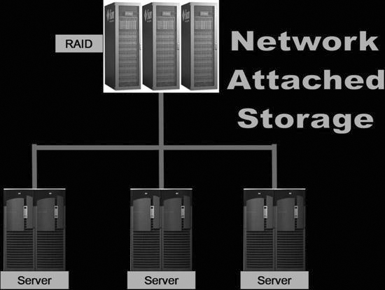
• NAS (Figure 10-19): NAS servers are stand-alone RAID arrays that are attached directly to the network. Multiple NAS servers can be attached to one network to provide additional fault tolerance, and the load can be balanced throughout the servers.
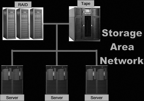
• SAN (Figure 10-20): A SAN is a high-speed, special-purpose network (or subnetwork) that links different kinds of data storage devices with associated data servers, such as disk array controllers and tape libraries. SANs are becoming more popular in health care because of plummeting costs of magnetic disk storage. A SAN can be used by multiple departments within an institution and provide exceptional response speed for called-up data. The RAID levels can still be taken advantage of when they are used in conjunction with a SAN.
Archive Considerations
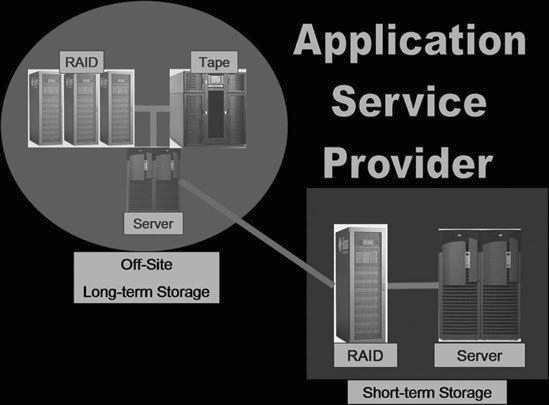
PACS archives are chosen for many reasons, including system need, system cost, and system compatibility. Many hospitals do not have the capital funds or the personnel to implement and operate the complex archive that is needed for a PACS. These hospitals have sought out other alternatives. One such alternative is an application service provider (ASP). An ASP is a company that provides outsourcing of archiving and management functions for a pay-per-use or pay-per-month charge. ASPs give smaller institutions access to the level of hardware and software they could not otherwise afford. Moreover, they assume responsibility for the day-to-day management of the archive system. Many ASP models have a short-term archive located on hospital premises, and the long-term archive is handled at the off-site location run by the ASP company (Figure 10-21). The short-term archive may be leased by the ASP, and the controller will prefetch images from the long-term off-site storage during the evening and night hours for the next day’s schedule.
Another common use for an ASP is as a disaster recovery mechanism. Disaster recovery involves making copies of each tape or disk and sending them to another building or off-site location or, by using the ASP model, shipping them to an outside company for storage on a pay-per-use policy. Even larger institutions have difficulty purchasing the proper amount of storage for disaster purposes. With proper disaster recovery, a complete copy of the archive is housed in another location and immediately available if the front-line archive goes down for any reason. With an ASP, however, the data may be housed in another state in a large storage silo, and the duplicated data may not be immediately available. There are many facets to disaster recovery, but a discussion of them is outside the scope of this textbook. The most important thing to know is that backups are completed each day on the image manager database and that there must be some sort of contingency plan should disaster strike the archive room.
The archive is a complex arrangement of servers, databases, and storage devices. It is the most integral part of a PACS and is in general the most difficult piece to fully understand. This chapter presents an overview of the topic but by no means has presented the information needed to successfully purchase or operate a PACS archive.
PACS Peripheral Devices
The previous chapters discussed the digital image acquisition process, PACS workstations, and archive systems. This chapter introduces you to three other components that are common in a PACS: film digitizers, imagers, and CD burners. Each of these three technologies plays an important role in the PACS.
Film Digitizers
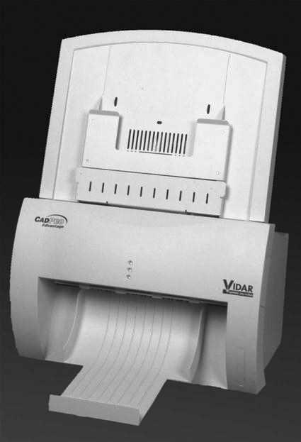
Another way to take a projection radiograph to a digital format other than photostimulable phosphor or flat-panel digital technology is by using a film digitizer. The film digitizer (Figure 10-22) scans the analog film and produces numeric signals for each part of the scanned film. The numbers are fed into a software application that is attached to the scanner, and the scanner digitally reproduces the image using the numeric signals that represent each part of the radiograph.
There are two major types of film digitizers; one type uses laser technology, and the other type uses charge-coupled device (CCD) technology. Both are equal in quality, but currently the CCD digitizers are less expensive.
Laser Film Digitizers
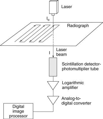
A laser film digitizer uses a helium neon laser beam to convert the analog film image into a digital image (Figure 10-23). A laser inside the digitizer is bounced off a series of mirrors and scanned across the image. A photomultiplier tube picks up the light that is transmitted through the film. The laser scans one line at a time, and the photomultiplier picks up a very small area and then moves to the next area. The electrical signal is then sent to an analog-to-digital converter where the signal is translated into numbers based on the optical density of the film and the signal received. The numbers are then displayed on a monitor based on a look-up table (LUT) that indicates which shade of gray is associated with each number.
Laser digitizers are considered the gold standard for film digitization, and they have been around since approximately 1990. These digitizers can scan at various resolutions up to 5K and 12 bit, depending on the application need, and can scan an image in less than 25 seconds, depending on the scanning resolution. The disadvantages of laser digitizers include their expense and service needs, including maintenance, calibration, and quality control (QC) tests.
CCD Film Digitizers
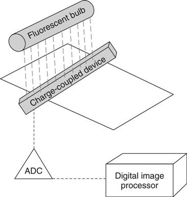
A CCD film digitizer uses fluorescent bulbs that shine through the film and a CCD array that detects the light and transforms it into an electrical signal (Figure 10-24). The signal is then sent to an analog-to-digital converter and changed into a number that represents the intensity of light that passed through the film. As with the laser digitizer, the number is referenced against a LUT, and an image is displayed on a monitor.
The CCD digitizers are less expensive than the laser digitizers but somewhat slower. A CCD digitizer can take up to 80 seconds to scan one film through the digitizer, and it can also have problems with extreme light and dark areas on the film. However, the CCD digitizer image quality has improved over the years, and many radiologists say that the quality is adequate for their needs.
Common Uses of Digitizers
There are many uses for the film digitizer in the modern radiology department. Most departments list the following reasons for using a digitizer:
Imagers
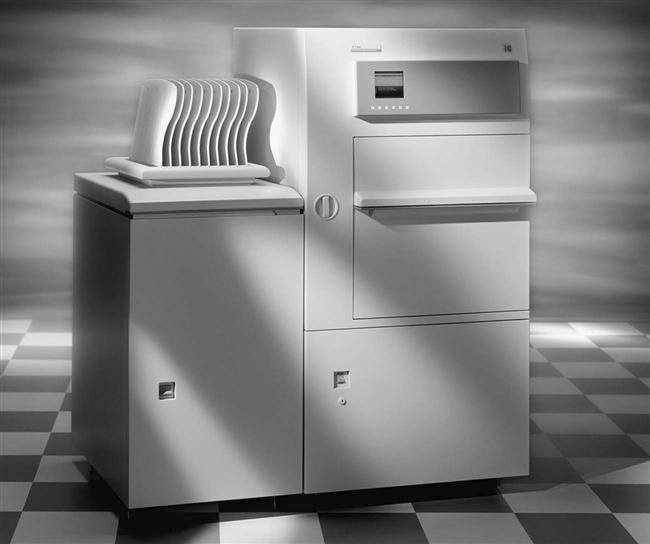
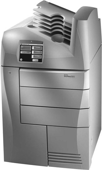
Imagers, also known as film printers, receive an image from a workstation and print the image based on printer LUTs and preset print layouts. Both of these parameters vary for each modality that produces digital images. There are two major types of imagers: wet (chemical) laser imagers (Figure 10-25) and dry laser imagers (Figure 10-26).
Wet Imagers
Wet imagers use chemicals to process the film that has been exposed to the laser. The laser beam produces an intensity of light that is proportional to the signal being received to regulate the optical density recorded on the film. The laser emits a red light, so the film that is used must be red sensitive. As mentioned earlier, conventional film has silver halide crystals suspended in an emulsion; the wet laser film is not much different other than being red sensitive so that the laser may etch the image into the film. Because this film is sensitive to red light, it must be placed in its film magazine and processed in total darkness. This processing takes place in a bath of chemicals just like film used in the traditional film/screen department.
Because wet imagers require chemicals, they must be placed in a well-ventilated area with proper drainage and plumbing. Because of these requirements, fewer departments install this type of imager. Wet imagers also take up much more space than the dry imagers, and the cost of chemicals, disposal, and maintenance make them a less popular choice than dry imagers.
Dry Imagers
Dry imagers use heat to process the latent image that is etched into the silver emulsion by the laser. Just like conventional film, dry laser film also has silver within its emulsion, but instead of silver halide crystals, the dry film has silver behenate. The film is exposed with a laser in a fashion similar to the wet imager. The silver salts are then exposed to heat and turn to metallic silver to create the image on the film.
Dry imagers have been found to have slightly worse quality than wet imagers, but the dry imagers take up less space and require no special locations. The dry imager film quality tends to degrade over time, and it is more sensitive to heat and humidity than conventional film, especially if the film is stored in a warm environment. Moreover, because the silver salts that make the image are still on the film after it is processed, the image can gain more density when stored in a high-heat area. The major advantage to the dry imager is that it only requires an outlet and a network connection to connect to the departmental modalities.
Common Uses of Imagers
Even though the future of radiology is a filmless environment, there will always be a need for producing a hardcopy film. The following list outlines a few reasons why film can and will be used in what nevertheless is called the filmless radiology department.
CD/DVD Burners
Early PACS advocates used cost savings to justify purchasing a PACS, but we have seen that there remains a need for hard copies. Film printing is a costly part of a PACS because laser film is expensive, more expensive than conventional film. Most hospitals try to reduce the amount of printing done in the department. One alternative to printing hard copies is to burn images to an optical disk.
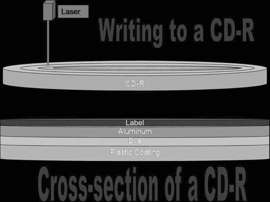
Remember from Chapter 7 that CDs and DVDs are both thin injection-molded polycarbonate plastic disks. The disk is impressed from a mold to form microscopic bumps that indicate either a 1 or a 0 to the computer. Over the bumps is a reflective layer of aluminum covered with a clear protective coat of acrylic. In a DVD there are multiple layers of the polycarbonate plastic. Aluminum is used behind the inner layers, and gold is used behind the outer layers. The gold is semi-reflective so the laser can penetrate to the inner layers of plastic. With a burner, the information is burned onto the disk starting in the center and spiraling out to the edge of the disk. The laser will burn a tiny depression (pit) into the disk to represent the data being saved. A burned disk will be a series of pits and lands, areas that were not burned by the laser (Figure 10-27).
All PACS vendors offer the ability to burn images to a CD or DVD for the purpose of sharing the images outside of the PACS. When a disk is burned with the patient’s images, a DICOM viewer is also burned onto the disk. When the disk is put into a drive, the software automatically launches and displays the images. The software is generally very intuitive and easy to use and allows for minor image enhancements such as window/level adjustments and simple measurements.
Common Uses of Burners
CDs and DVDs can be used in most of the same applications as the printed film with the exceptions that CDs and DVDs cannot be used as a fail-safe mechanism nor can they be used by those departments that are in difficult locations. Many referring physicians prefer having the images on disk rather than film because it takes up less space, can be added directly to the patient’s office chart, and the images can be manipulated.
Disks also are much less expensive to produce and send out to physicians. One sheet of dry laser film costs approximately 48 cents, whereas a CD costs approximately 28 cents. The CD can hold multiple studies, and multiple sheets of film would be needed to print an entire study. The CD is also much less expensive to mail than the film. Disks will become much more common outside of the radiology department as the advantages are seen by those outside of the department.
Summary
• The image manager contains the master database of everything that is in the archive.
• The archive server consists of the physical storage devices of the archive system.
• Most PACS archives are set up with short-term and long-term archive tiers.
• A short-term tier is commonly a redundant array of independent (inexpensive) disks (RAID).
• A RAID is composed of several magnetic disks or hard drives that are linked together in an array.
• RAID 5 is the most common RAID level used in PACS archives.
• Long-term storage devices hold historic images for comparison reading on the workstations.
• Tape, optical disk, and magnetic disks are commonly used as long-term archive solutions.
• Wet imagers use chemicals to process the film that has been exposed to the laser.

