Chapter 21 Pacemakers and Implantable Cardioverter-Defibrillators Essentials for Clinicians
Please go to expertconsult.com for supplemental chapter material.
Pacemakers: Definitions and Types
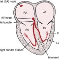
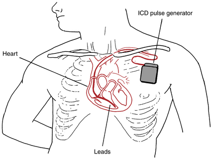
A pacemaker consists of two major components: (1) a pulse generator (battery and microcomputer) and (2) one or more electrodes (also called leads). The electrodes can be attached to the skin (in the case of emergency transcutaneous pacing), but more often are attached directly to the inside of the heart (Fig. 21-1).
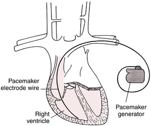
Permanent pacemakers have both the generator and electrode(s), also called leads, implanted inside the body (see Fig. 21-1). Electronic pacemakers are used for three major purposes:
• They can supplant impaired atrial impulse formation in severe sinus node dysfunction.
• They can supplant impaired AV conduction in heart block syndromes, thereby restoring normal AV timing (synchrony∗).
• They can compensate for left bundle branch block (LBBB) conduction abnormalities, especially with heart failure, by providing synchronization∗ of right and left ventricular contraction. This use is called resynchronization therapy or biventricular pacing.
All contemporary pacemakers are capable of sensing intrinsic electrical activity of the heart and are externally programmable (adjustable) using special computer devices provided by the manufacturers. Pacemakers are usually set to operate in an on-demand mode, providing electronic pacing support only when the patient’s own electrical system fails to generate impulses in a timely fashion. Modern pacemaker batteries last on average between about 8 and 12 years, depending on usage.
Single- and Dual-Chamber Pacemakers
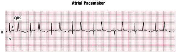
Single-lead (or single-chamber) pacemakers (see Fig. 21-1), as their name indicates, are used to stimulate only one chamber (right atrium or right ventricle). Atrial single-lead pacemakers (with the lead positioned in the right atrium) can be used to treat isolated sinus node dysfunction with normal AV conduction (Fig. 21-2). In the United States, single-lead atrial pacemakers are rarely used. Even patients with isolated sinus node dysfunction usually receive dual-chamber devices because AV conduction abnormalities often develop later as the patient ages.
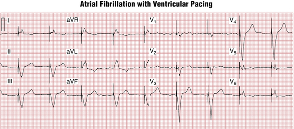
Ventricular single-lead pacemakers (with the lead positioned in the right ventricle) are primarily used to generate the heartbeat in patients with chronic atrial fibrillation with an excessively slow ventricular response. The atrial fibrillation precludes effective atrial stimulation so that there is no reason to insert an atrial lead (Fig. 21-3).
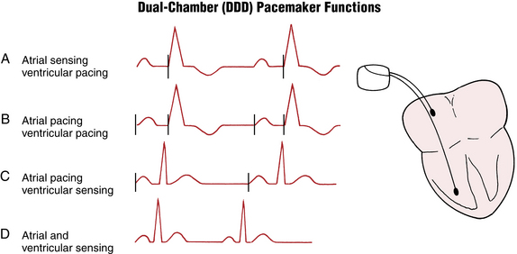
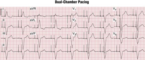
In dual-chamber pacemakers, electrodes are inserted into both the right atrium and right ventricle (Figs. 21-4 and 21-5). The circuitry is designed to allow for a physiologic delay (normal synchrony) between atrial and ventricular stimulation. This AV delay (interval between the atrial and ventricular pacemaker spikes) is analogous to the PR interval under physiologic conditions.
ECG Morphology of Paced Beats
A paced P wave demonstrates a pacing spike followed by a P wave (see Fig. 21-2).
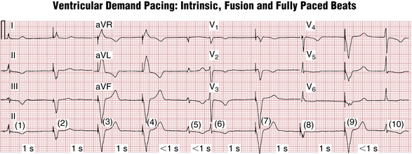
A paced QRS beat also starts with a pacing spike, followed by a wide QRS complex (see Figs. 21-3 and 21-6). The wide QRS is due to the fact that activation of the ventricles starts at the tip of the lead and spreads to the other ventricle through slowly conducting myocardium, similar to what occurs with ventricular premature beats (VPBs) or ventricular escape beats. The QRS morphology depends on the lead (electrode) position. The most commonly used ventricular electrode site is the right ventricular apex. Pacing at this location produces a wide QRS (usually resembling an LBBB pattern; see Chapter 7) with a leftward axis (QRS deflections are predominantly negative in leads II, III, and aVF and positive in leads I and aVL).
As with VPBs, the T waves in paced beats normally are discordant—directed opposite to the main QRS direction (see Figs. 21-3 and 21-5). Concordant T wave (i.e., pointing in the same direction as the paced QRS) during ventricular pacing may indicate acute myocardial ischemia (see following discussion).
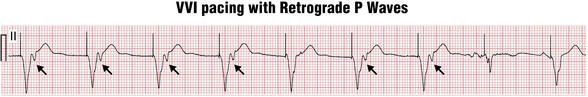
Ventricular paced beats, similar to VPBs, can also sometimes conduct in a retrograde manner to the atria, producing near simultaneous atrial and ventricular depolarization and contraction (Fig. 21-6). When this occurs repeatedly, atrial contraction against the closed AV valves produces recurrent, sudden increases in jugular (and pulmonary) vein pressures, which may be seen as “cannon” A waves in the neck examination. Of note for clinicians, these abrupt pressure changes, in turn, may activate a vagal reflex and cause severe symptoms (palpitations, pulsation in the neck, dizziness, and blood pressure drop), often referred to as the pacemaker syndrome. Therefore, patients in sinus rhythm with AV block are usually implanted with dual-chamber pacemakers so that ventricular pacing will occur after atrial pacing, maintaining physiologic AV timing (synchrony).
Electronic Pacemaker Programming: Shorthand Code
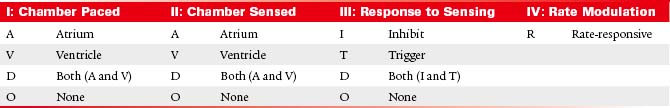
Historically, pacemaker programming has been described by a standard three- or four-letter code, usually followed by a number indicating the lower rate limit. Although many new pacing enhancements have been introduced since the inception of this code, it is still widely used (Table 21-1).
Single-Chamber Pacemaker Programming
As noted, modern pacemakers are programmed in the on-demand mode providing pacing support only when needed. In the case of a single-chamber pacemaker this function is accomplished by specifying the lower rate limit (for example 60 beats/min). The pacemaker constantly monitors the patient’s heart rate in the implanted chamber on a beat to beat basis. Any time the rate drops below the lower rate limit (in the case of 60/min, the critical pause after a spontaneous QRS complex will be >1 sec), the pacemaker will deliver a pacing stimulus (Fig. 21-7). This corresponds to the code: VVI 60.
Dual-Chamber Pacemaker Programming
Depending on the atrial rate and the status of intrinsic AV conduction, dual-chamber pacemakers can produce four different combinations of pacing/sensing ECG patterns (Figs. 21-4, 21-7 and 21-8):

Figure 21-8 DDD pacing. Four different pacing/sensing combinations can be present depending on the sinus rate and atrioventricular (AV) conduction. See also Figure 21-4.
This programming corresponds to the code in Table 21-1.
On-demand programming has significant advantages, including prolonging battery life and avoiding unnecessary pacing especially in the ventricle. Its downside is the possibility to mistake external electrical signals for the patient’s own electrical activity. This would result in pacemaker inhibition and inappropriate withholding of pacing. Situations like this can occur, for example, with the use of electrosurgical equipment or exposure to strong electromagnetic fields, such as created by magnetic resonance imaging (MRI) machines. In these cases pacemakers can be reprogrammed in asynchronous mode (DOO or VOO) and will provide pacing at the lower rate limit regardless of ambient electrical activity. DOO mode is used in MRI-compatible pacemakers for the duration of the scan.
1. The maximal tracking rate is the highest ventricular pacing rate allowed in response to atrial sensing and is usually set at 110 to 150 beats/min. It is designed to prevent excessively rapid ventricular pacing during supraventricular arrhythmias. (Note the distinction between the maximum activity-related rate, the highest rate the pacemaker will fire during exercise as part of its rate-responsiveness, and the maximal tracking rate, the absolute highest the pacemaker will fire in response to atrial sensing.)
2. Automatic mode switching changes the pacing mode from DDD to VVIR in response to sensing high atrial rates suggestive of atrial flutter or fibrillation to regularize and slow ventricular pacing rhythm during these arrhythmias.
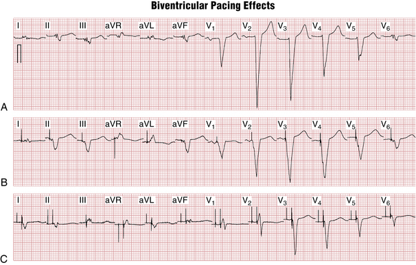
Biventricular Pacemakers: Cardiac Resynchronization Therapy
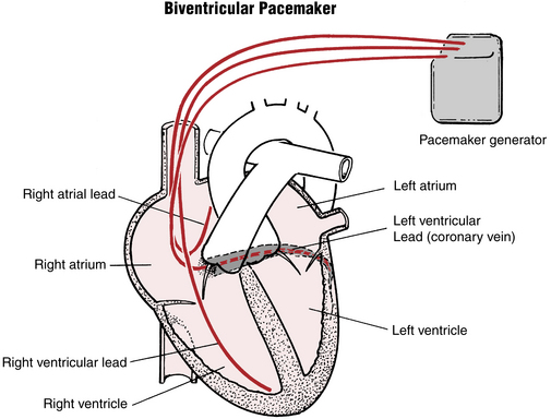
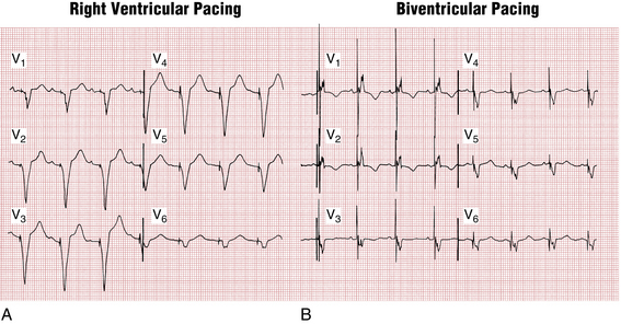
This positive effect is accomplished by biventricular pacing. In addition to the usual right ventricular pacing lead, another electrode is placed to stimulate the left ventricle. Usually this second lead is advanced transvenously through a branch of the coronary sinus on the posterolateral wall of the left ventricle (Fig. 21-9) because this is the latest activated area with intrinsic LBBB or with right ventricular pacing.
Both ventricles are then paced simultaneously, producing fusion-type QRS complexes (Figs. 21-10 and 21-11) that represent a “hybrid” between those seen with pure right and left ventricular pacing. The QRS morphology can be quite variable depending on the position of the left ventricular electrode, but usually the QRS has prominent R waves in leads V1-V2 (RBBB-type morphology due to posterior left ventricular wall activation from back to front) as well as Q waves in leads I and aVL (left ventricular electrode activating the heart from left to right). The QRS duration during biventricular pacing is usually shorter than with right ventricular pacing or with an intrinsic LBBB.
ECG Diagnosis Related to Paced Rhythms
Atrial Fibrillation
The usual pacing mode in atrial fibrillation is VVI(R). Paced QRS complexes occur at regular intervals masking the most obvious sign of atrial fibrillation—irregular RR intervals. If only V-paced beats are present, most computer ECG interpretation algorithms will read this as “ventricular paced rhythm” without commenting on the atrial activity. Unless you specifically mention atrial fibrillation in the report, it will go unnoticed and the patient might be exposed to the risk of a stroke if not properly anticoagulated. The best lead to evaluate atrial activity is lead V1 because it usually shows the highest amplitude fibrillatory signals (see Fig. 21-3).
ST-T Wave Changes Due to Acute Myocardial Ischemia
Although ischemic ST-T wave changes are often obscured by pacing (similar to LBBB), sometimes severe ischemia can still be visible as disappearance of the normal QRS-T discordance during ventricular pacing. Similar to the signs of ischemia in LBBB, concordant QRS-T pattern and concordant ST segment depressions in leads V1-V3 point to severe myocardial ischemia during ventricular pacing (Fig. 21-12).
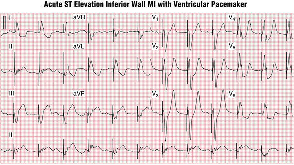
Figure 21-12 Temporary transvenous pacing in a patient with acute inferior (posterior) wall ST segment elevation myocardial infarction. Concordant QRS-ST-T pattern in lead II and reciprocal ST segment depressions in leads V2-V3 during ventricular pacing suggest acute myocardial ischemia (similar to ischemic changes in left bundle branch block [LBBB]). The rhythm strip demonstrates sinus bradycardia with heart block and AV dissociation (most likely due to complete AV heart block; see Chapter 17).
Cardiac “Memory” T Wave Inversions
Ventricular pacing produces electrical changes in the heart that last a long time after the pacing stops (process called cardiac memory). In patients who are paced intermittently, these changes can be seen in nonpaced beats as T wave inversions in the leads that showed predominantly negative QRS during ventricular pacing (usually precordial and inferior leads) (see Fig. 21-7). These changes look very much like T wave inversions due to myocardial ischemia (Wellens’ syndrome). However, leads I and aVL usually show upright T waves in normally conducted beats after a period of ventricular pacing, although anterior ischemia is often associated with T wave inversions in these leads.
Implantable Cardioverter-Defibrillators
Modern ICD systems resemble pacemakers in appearance, but with slightly larger generators and thicker right ventricular leads (Fig. 21-13). They are both implanted in a similar fashion. ICDs differ from the usual external defibrillation paddles or patches because in ICDs electrical current passes between one or two special coils on the ventricular lead and the generator.
All current ICDs are capable of pacing and can be single-chamber, dual-chamber, or biventricular.
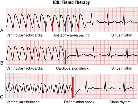
Arrhythmia detection is based primarily on the heart rate and can be programmed in up to several different heart rate zones (for example, slow VT, fast VT, and VF zones at 160, 180, 200 beats/min). Arrhythmia treatments then can be set up separately in each of the zones (Fig. 21-14) as part of automatic “tiered” (ramped) therapy.
Recognizing Pacemaker and ICD Malfunction
Pacemakers are very reliable devices and pacemaker malfunctions are rare, especially after the acute postimplant phase. The commonly encountered problems are: failure to capture, failure to sense, and failure to pace.
Failure to capture is characterized by appropriately timed pacing spikes that are not followed by electrical activity of the heart (Fig. 21-15). The most common causes are lead dislodgment, leakage in the pacing circuit, inappropriately set pacing outputs, and rise in pacing threshold due to ischemia, fibrosis, or electrolyte abnormalities (e.g., hyperkalemia).
Failure to sense (see Fig. 21-15) is characterized by excessive and inappropriately timed pacing activity. It can be due to lead dislodgment, inappropriately set sensitivity, or changes in intrinsic signal amplitude due to ischemia, electrolyte abnormalities, or fibrosis.
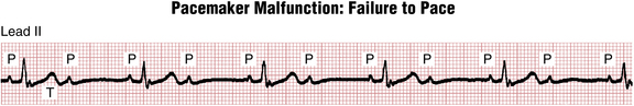
Failure to pace (Fig. 21-16) is usually due to the pacemaker inhibition by noncardiac electrical signals, such as from skeletal muscle, the diaphragm, external electromagnetic sources (electrocautery, lithotripsy, MRI machines), or electrical interference (“noise”) created by fractured pacemaker leads.
Magnet Response of Pacemakers and ICDs
The response of pacemakers to magnet application is different from that of ICDs.
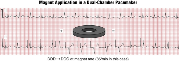
Magnet application over the pacemaker generator header (top area where the lead exits) switches most pacemakers to an “asynchronous” mode (DDD → DOO; VVI → VOO) at a preset magnet rate (Fig. 21-17), which varies between manufacturers and indicates the battery status. As the battery is depleted, the magnet rate usually slows.
1. Is there appropriate sensing on both atrial and ventricular channels?
2. Is there appropriate capture on both channels?
3. Is the magnet pacing rate consistent with full battery life or partial depletion? (In the example shown in Figure 21-17, the magnet rate of 85 beats/min was indicative of full battery life for this manufacturer.)
Pacemaker and ICD Implantation: Specific Indications
In general, pacing is indicated in three major settings:
• Symptomatic bradycardia or pauses (especially due to sinus node dysfunction or AV heart block) at rest or during exercise. This category also includes abnormalities induced by medications that are essential (e.g., tachy-brady syndrome exacerbated by beta blockers). Note: Pacemaker implantation is not indicated in asymptomatic sinus bradycardia.
• Symptomatic conduction abnormalities with high risk of abrupt progression to a life-threatening condition (e.g., Mobitz II second-degree heart block; major conduction abnormalities associated with certain neuromuscular diseases, such as myotonic dystrophy).
• Syncope when causes other than bradycardia (especially sustained VT) have been ruled out.
• Resuscitated victims of cardiac arrest due to VT or VF due to nonreversible causes (for example, not associated with acute infarction or metabolic abnormality)
• Patients with sustained VT and structural heart disease (ischemic or nonischemic cardiomyopathy)