[level-membership-for-cardiovascular-category]
29 Pacemaker Troubleshooting and Follow-up
 Bidirectional Telemetry
Telemetry is the ability to transmit information or data from one device to another, a capability that was essential to the introduction of pacemaker programmability. This is the ability to noninvasively change the functional and diagnostic parameters of the pacing system by coded commands transmitted to the pacemaker from a programmer.1–4 The first generation of programmable pacemakers used unidirectional telemetry from the programmer to the pacemaker but was not able to transmit data from the pacemaker to the programmer. This limited the confirmation of a programming change that was electrocardiographically silent (e.g., sensitivity, refractory period) when a parameter was programmed.
Bidirectional telemetry is communication in two directions. With respect to pacing systems, this means that the pacemaker and programmer can communicate with each other, an essential capability for the development of the multiple diagnostic capabilities that are the subject of this chapter.5,6 First implemented in rechargeable pacemakers, bidirectional telemetry was developed to confirm the proper alignment of the recharging head with the implanted pacemaker. When the recharging wand was not aligned properly with the pacemaker, there was an audible beep from the charging unit to notify the patient and whoever was in attendance of this condition. When the two devices were properly aligned, the system was silent.
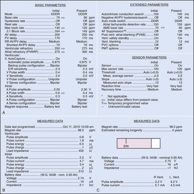
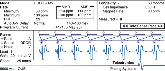
Bidirectional capability was next applied to confirmation of programming. This was particularly valuable for those parameters that did not result in an overt change in pacing system performance and could not be independently identified on an electrocardiographic recording. This ability is essential for the DDDR pacemaker and modern implantable cardioverter-defibrillators (ICDs), because these devices can have dozens of independently programmable parameters, most of which are not readily identifiable on the electrocardiogram (Fig. 29-1, A). Bidirectional telemetry allows interrogation of programmed parameters and measured data when the patient is seen during follow-up for routine evaluation, during remote follow-up interrogation, or for a suspected pacing system malfunction. Without this feature, there would be no way to determine the current settings of a device for features other than rate and pulse width. It also makes the retrieval of detailed data collected by the pacemaker in its various event counters feasible. Presently, interrogation of pacemaker settings and data can be accomplished remotely. This technique uses a device located in the patient’s home, a physician’s office, or anywhere an Internet connection or telephone service (wired or cellular) connection is available. Data are retrieved from the device and sent to a central receiving station. The data are made into a report and then can be faxed to the appropriate individual or made available through an Internet website portal. Although the technology exists to allow programming remotely, this is not currently available because of regulatory issues.
Measured Data
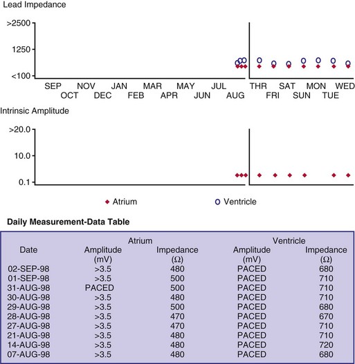
Complementing the interrogation of programmed data is the provision of measured data, including data obtained from the pacemaker detailing information on lead and battery function at evaluation. Information regarding demand and asynchronous rates may also be measured (Fig. 29-1, B). Telemetry allows this information to be transferred from the pacemaker to the programmer for evaluation by the clinician.
Battery Status
Although not all systems provide the information in the same manner (some are graphic and others are numeric), data concerning battery function often include a measure of battery voltage, impedance, and current drain.7–11 All three parameters are interrelated. The battery current drain is a measure of the average current being drawn from the battery, assuming 100% pacing at the programmed rate and output settings. Inhibition or pacing at higher rates, as might occur with intrinsic rhythm or sensor drive, respectively, directly affects the functional battery current drain, as do changes in lead or stimulation impedance. The reported current drain is only an estimate of the actual battery current drain. Newer devices are able to estimate remaining longevity based on true current drain measurements, giving a much more accurate assessment (see Fig. 29-1, C).
Given the degree of programmability of most current pacemakers, a dual-chamber pacemaker programmed to pace all the time at maximal output on each channel may last only 2 years. An identical model programmed to outputs of 2.5 V or lower on each channel that are inhibited a significant portion of the time may be anticipated to function properly for 10 years or longer. It would be inappropriate to follow the second unit on a monthly basis beginning 1 year after implantation, whereas it would be equally inappropriate to plan only annual checks on a pacing system programmed with high outputs and 100% pacing. By following some measure of the status of the battery, either directly or indirectly, the clinician can achieve a qualitative assessment about when to increase the frequency of pacing system follow-up.12
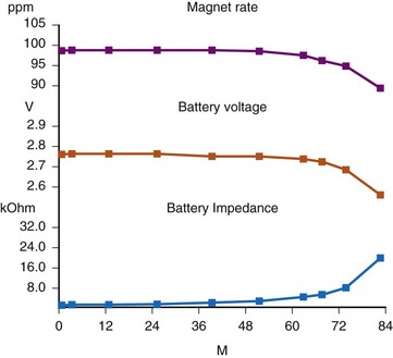
There are two primary indicators of battery status: battery voltage and battery impedance. Battery voltage progressively decreases over time. The lithium/iodine (Li/I2) power cell is the most common power source in pacemakers, whereas the power source in an ICD is lithium/silver vanadium oxide (Li/VSO). Some of the newer pacemakers are now using Li/VSO–polycarbon monofluoride (LVSO/P). The nominal unloaded output voltage of the Li/I2 cell is 2.8 V, with each manufacturer triggering the RRT indicator at a specified battery voltage based on circuit design considerations. LSVO/P in pacemaker application has an initial voltage of 3.20, with an early drop to 2.90 V, where it plateaus, then drops to an elective replacement voltage of 2.60 V. The battery voltage and programmed output voltage are not identical. The “programmed output voltage” is achieved by modifying the 2.8-V battery output with either voltage multipliers or charge pumps to provide a higher voltage. The battery voltage can also be divided to deliver a voltage lower than 2.8 V. As energy is consumed, the battery voltage progressively decreases because of increased internal impedance. Even with decreasing battery voltage, the device circuitry is designed to maintain the stability of the programmed voltage delivered to the patient. The ability to track the progressive decrease in battery voltage and increase in battery impedance provides an effective guide to the clinician regarding the frequency with which the pacing system should be routinely checked for signs of battery depletion (Fig. 29-2). In addition, the measured battery voltage is affected by the battery current drain: the higher the current drain, the lower the battery voltage.
Battery voltage and impedance may be tracked together or individually. If these measurements are provided to the manufacturer’s technical service engineers, along with the programmed parameters and an estimate of the percentage of pacing versus inhibition, the remaining longevity of that pacing system can be estimated with reasonable accuracy, assuming that the various parameters remain stable. These calculations have more recently been incorporated into the programmer interface to provide an online estimate of longevity in years or months. These estimates are sometimes shown as a range based on the tolerances of the battery measurements (i.e., giving minimum and maximum ranges of longevity), as well as an estimate based on present current drain and actual device use based on data acquired from the event counter diagnostics (see Fig. 29-1, B).
Lead Status
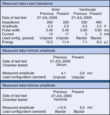
The clinician can use knowledge of lead impedance to monitor and identify a developing mechanical problem with the lead. This requires baseline and historical data to recognize subtle changes that may reflect conductor fracture or an insulation breach. It is essential to know what device is being used to make these measurements. As noted previously, different devices may obtain these data at different points of the pacing stimulus. Because of these differences, the impedance measurement obtained with a pacing system analyzer at implantation may be significantly different from that obtained by telemetry from the implanted pacemaker moments, if not years, later. This difference does not necessarily imply a problem. Furthermore, impedance may naturally evolve over time, with a fall in impedance occurring during the days to weeks after implantation, followed by a gradual rise toward the initial measurements. Multiple factors may affect impedance, particularly in a unipolar system. For example, measurements obtained during deep inspiration may significantly differ from those obtained during maximal exhalation. In the same patient, impedance measurements based on a single-output pulse have been reported to vary by 100 ohms (Ω), or even more, during the same follow-up evaluation, while remaining consistent with normal function. If a marked change in lead impedance from previous measurements (e.g., >200 Ω) is encountered during a routine follow-up evaluation, the pacing system should be further evaluated.13,14 If the patient has no clinical symptoms and has stable capture and sensing thresholds, surgical intervention would be premature, although more frequent follow-up in the office or by remote interrogation would be prudent. However, a dramatic change in telemetered lead impedance in the presence of a clinical problem directs the physician toward the likely source of the difficulty (Fig. 29-3).
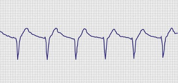
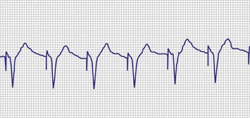
A dramatic fall in impedance usually reflects a break in the insulation.15–17 In a unipolar system, an insulation problem provides an alternative pathway for current flow starting closer to the pulse generator, resulting in less energy reaching the heart. An outer insulation break in a bipolar lead tends to result in “unipolarization” of the lead. The amplitude of the stimulus artifact as recorded by an analog electrocardiogram (ECG) is determined by the distance the current travels in the tissues from the cathode (tip electrode) to the anode (ring electrode or housing of the pulse generator). A normally functioning bipolar pacing system in which both active electrodes are inside the heart, separated only 1 to 2 cm, results in a small stimulus artifact. In a unipolar system, the current travels from the tip electrode to the housing of the pulse generator, and therefore the stimulus artifact is large despite equivalent output settings. Some of the newer digital ECG designs result in a marked signal-to-signal variation in amplitude as a result of the digital sampling rate of the recording system. Other recording systems create an artificial uniform amplitude artifact with any high-frequency electrical transient, thereby precluding differentiation of a bipolar from a unipolar pacing system based on the analysis of the ECG recording.
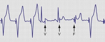
In a previously stable system, a mechanical problem developing with the lead—either a breach in the insulation or a conductor fracture—results in a change in the stimulation impedance, which may be reflected by a change in the ECG-recorded stimulus artifact (Fig. 29-4). In a bipolar pacing system, an insulation defect between the proximal conductor and the tissues of the body is not likely to affect capture thresholds, but it results in a larger stimulus artifact, making it appear unipolar. Depending on the actual location of the insulation failure in either the bipolar or the unipolar lead, stimulation of the extracardiac muscle contiguous to the insulation defect may occur. Insulation failures may also attenuate the electrical signal reaching the pacemaker, possibly resulting in sensing failure.
Programming of the output configuration to unipolar (most pacing systems, but not ICDs, now have this capability) may prevent the loss of capture and possibly undersensing from an internal short circuit. This does not prevent the oversensing behavior associated with make-break electrical transients generated by intermittent contact between the two conductors, as is caused by failed inner insulation. Typically, a bipolar lead with failed internal insulation exhibits a higher impedance when pacing is programmed to the unipolar rather than the bipolar output configuration.18,19 This is opposite to the expected higher impedance of a bipolar system. Although programming to a unipolar configuration may result in an apparent resolution of a malfunction, it is not a cure and should be considered only as a temporary measure, one that allows the observed problem to be managed on an elective rather than emergent basis. The malfunctioning lead should be replaced expeditiously.
An increase in lead impedance may be the result of a conductor fracture or a connector problem.20 When this occurs, the lead impedance often rises to high levels. It is inappropriate, however, to assume that a normal lead impedance is 500 Ω. Leads are available that are designed to have high impedance, with values ranging from 1500 to 2500 Ω. Other leads, at implantation, may have an impedance in the range of 250 to 300 Ω. Therefore, it is essential to look for a trend in serial lead impedance measurements rather than a single measurement. Impedance, taken in conjunction with the stability or changes in capture and sensing thresholds, is the best way to determine the condition of a pacing lead. A mechanical problem with the lead—either a conductor fracture resulting in high impedance or an insulation failure resulting in low impedance—eventually results in an overt clinical problem that can be identified by telemetric measurement of the stimulation impedance. If the impedance is sufficiently high, there is no current flow and no effective output. It must be understood that, although the telemetered event markers indicate a pace output, there may be loss of capture. The reduced current flow also results in a fall in the measured current drain of the battery. Note that any problem may be intermittent. This typically occurs when the two broken ends make contact at times but are separated at other times, or in the case of an insulation failure, when lead movement either opens the compromised area or pushes the edges of the break together, resulting in intermittent normal function.
Some pacemakers are able to report lead impedance measurements on a beat-by-beat basis, allowing the clinician to observe the digital readout of lead impedance on the programmer screen over many cycles. As with the oscilloscopic monitoring of the pulse wave morphology, this technique reduces but does not eliminate the incidence of false-negative results. A further enhancement is the “automatic periodic monitoring” of lead impedance, which results in a graphic display reporting the history of lead impedance performance. Measurements can be obtained continuously or daily. This increases the frequency of measurement, increasing the likelihood of diagnosing an intermittent lead problem and possibly intervening on an automatic basis (Fig. 29-5). Some devices respond by automatically programming the pacemaker from bipolar polarity to unipolar in the presence of either a marked rise in impedance, reflecting a conductor fracture,21 or a marked drop in impedance, consistent with an insulation failure.
Event Marker Telemetry
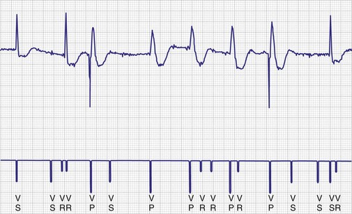
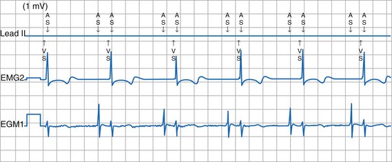
To facilitate interpretation of the paced rhythm, almost all modern pacing and ICD systems incorporate the ability to transmit information regarding real-time pacing system behavior to the programmer. These data are displayed on the programmer screen and may also be printed as well. Both paced and sensed events are communicated to the programmer. Displayed as a series of positive or negative marks, with or without alphanumeric annotation, these are generically termed event markers. They have the greatest diagnostic value when superimposed above or below a simultaneously recorded surface ECG (Fig. 29-6). Some systems also display the duration of the atrial and ventricular refractory periods and interval measurements. Others show events that are sensed during the refractory period even though they do not play a role in altering the system timing (i.e., they are sensed but not used). Events may be displayed either in real time or after the tracing has been frozen on the programmer screen using cursors to identify the interval of interest. If the real-time monitor screen method is used to show the rhythm and event markers, the tracing may be frozen and then printed for inclusion in the medical record.
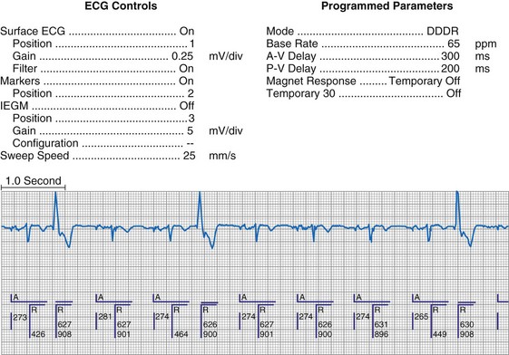
Figure 29-6 Surface ECG and simultaneous event markers.
Data are from a Pacesetter Trilogy DR+ Model 2360 (St. Jude Medical CRMD, Sylmar, Calif).
Event markers (also called marker channels, annotated event markers, and main timing events by various manufacturers) are most effectively used when they are displayed with a simultaneously recorded ECG rhythm.22–25 Without the ECG, the event marker simply reports the behavior of the pacemaker. This information is valuable in showing that an output has been released or that sensing has occurred. It does not confirm that the stimulus effectively resulted in capture, or that a sensed event was a true atrial or ventricular depolarization. The presence of an output marker does not confirm that the stimulus even reached the heart. The output marker serves only to confirm that the pacemaker delivered a stimulus from its output circuit. This notation is transmitted directly from the pacemaker to the programmer by way of the telemetry module. An open circuit (e.g., a fractured conductor coil) may preclude the output pulse from reaching the heart, but the pacemaker would indicate that an output pulse was released. Similarly, a native depolarization may not be sensed, allowing the pacing stimulus to be released at a time when the myocardium is physiologically refractory. If the markers reported that an event was sensed on the atrial channel and was followed by a ventricular output pulse after a preset delay (known as P-wave synchronous ventricular pacing or tracking), the clinician would know that the pacemaker was capable of sensing in the atria and pacing in the ventricles. Without a simultaneously recorded ECG, it would be impossible to determine whether the pacemaker was responding to inappropriate signals on the atrial channel, whether the ventricular stimulus was effective, or whether a native QRS complex was present but not sensed. Therefore, telemetered event markers are most effective when displayed with a simultaneously recorded ECG.
Event Marker Displays
The next improvement was to transmit coded signals representing paced and sensed events from the pacemaker to the programmer. The programmer reconstituted these signals into a series of varying-amplitude pulses or alphanumeric labels representing paced or sensed events. These could be either displayed on a monitor screen or recorded using a printer integral to the programming system, which allowed for the simultaneous recording of a surface ECG acquired by way of a separate set of cables. The simultaneous ECG and markers allowed the clinician to correlate the behavior of the pacemaker directly with the patient’s rhythm, to determine whether the system is functioning properly. A calibration signal composed of a series of different amplitude pulses or a legend of the cryptic labels allowed the clinician to interpret the various markers (Fig. 29-7). In an early series of markers, the largest pulse represented a pacing output, the intermediate one indicated a sensed event, and the smallest represented either the end of the refractory period or a sensed complex that occurred during the refractory period. With the advent of dual-chamber pacing systems, a marker pulse extending above the baseline identified atrial events, and ventricular events were labeled with a pulse extending below the baseline. This type of marker system has become obsolete, and there are very few devices remaining as active implants that use this scheme.
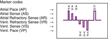
One method for single-chamber pacing systems with event marker telemetry uses the letter P to reflect a paced event and S to represent a sensed event. This may cause confusion with other dual-chamber systems in which the letter P reflects a sensed atrial event indicative of a native P wave (with which most medical personnel are familiar, based on their knowledge of the standard ECG). The interpretation of the alphanumeric event markers is often product specific, and the clinic personnel who evaluate the pacing system must take this into account (Fig. 29-8).
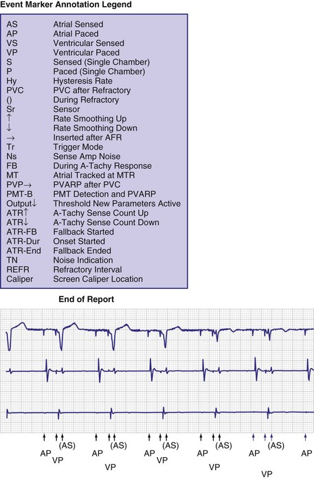
Other symbols may be used for a paced or sensed event and are usually displayed with an identifying key on the resultant printout. Each paced or sensed event may also be identified by a vertical line, going up in the case of atrial events and down for ventricular events. In some cases, a difference in the amplitude of these lines has been retained in conjunction with the alphanumeric lettering. Indeed, as the complexity of the devices increases, the variety of symbols and letters identifying specific events and behaviors is also increasing (see Fig. 29-8).
Laddergramming
Laddergramming is an advanced adjunct to the interpretation of clinical arrhythmias. It was incorporated in some programming systems by using the known programmed parameters of the pacemaker combined with the event marker information telemetry from the implanted pacemaker23–26 (Fig. 29-9). For all the elegance of these graphic interpretations of the pacemaker’s behavior, they still require the simultaneously recorded ECG rhythms. Although the pacemaker may be functioning normally, in that it is behaving properly with respect to its programmed parameters, failure to capture or properly sense would not be diagnosed from the various diagrams and markers without the simultaneously recorded surface ECG.27 Laddergramming has become a teaching tool at this time, because no programmers currently provide this level of graphic description.
Event Marker Limitations
Several limitations are associated with event marker telemetry. First, used alone, markers report the behavior of the pacemaker but do not allow the clinician to determine whether this behavior is appropriate for the patient.27 In this regard, markers are analogous to the hand-held digital counters that report pacing rates and intervals. The counters only detect and report the pacing stimuli, not whether these output pulses are effective in causing a cardiac depolarization, or whether native events are properly and consistently sensed. A long interval between consecutive pacing stimuli could reflect normal function because the pacemaker responded appropriately to a native complex, or it could represent a system malfunction with oversensing or no output (e.g., from intermittent lead fracture). Neither event marker telemetry nor the digital counters should be used independently of a simultaneously monitored ECG rhythm.
Most pacemaker event marker telemetry is limited to real-time recordings. The markers must be telemetered from the pacemaker to the programmer or another display system while the rhythm is being actively monitored. Neither the pacemaker nor the programmer can retrospectively provide markers for a previously recorded rhythm. If the pacemaker is responding to events that are not visible on the surface ECG, the event marker simply confirms this fact but does not identify the specific signal. An evaluation of sensed but otherwise invisible events requires intracardiac electrogram telemetry or an invasive procedure to record the signal from the implanted lead. Many premium-level pacemakers can store event markers with or without electrograms. Markers may be stored using a patient trigger (e.g., magnet application),28 a simple battery-operated radiofrequency transmitter, or on spontaneous activation of predefined algorithms or sequences of sensed or paced events.
Electrogram Telemetry
At implantation, the amplitude of the EGM is usually measured with a pacing system analyzer (PSA) that reports a millivoltage amplitude. The PSA uses its own unique set of filters, which frequently is not identical to those in the pacemaker’s sense amplifier. Therefore, the reported PSA signal, at best, provides an approximation of what the pacemaker effectively sees. Newer pacing system analyzers are now being introduced that will allow adjustment of the filters to match specific models of pacemakers and ICDs to eliminate this discrepancy. Likewise, the morphology of the EGM observed on a high-fidelity monitor is not identical to the signal as seen by the pacemaker, because filters in the pacemaker’s sense amplifier usually have a narrower band-pass and therefore block out some of the frequencies (Fig. 29-10). Examining the EGM recorded with a physiologic recorder or telemetry with a wide band-pass can provide valuable information on the slew rate, splintering of the intrinsic deflection, and other morphologic abnormalities.
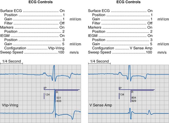
Figure 29-10 Side-by-side display of telemetered bipolar ventricular electrograms.
These signals were telemetered from a Pacesetter Affinity DR pacemaker, Model 5330 (St. Jude Medical CRMD, Sylmar, Calif).
Measurements of the peak-to-peak amplitude of the EGM, as recorded at implantation or as telemetered from an already-implanted pacemaker, are typically used to determine the sensing threshold. This approach may be inappropriate if the frequency content of the signal is outside the constraints of the band-pass filter of the sense amplifier. If the clinician wants to determine the sensing threshold for a given patient, the sensitivity of the system should be progressively reduced until the system no longer consistently senses the native signal. The least sensitive setting (usually identified by millivolt amplitude) at which there is consistent sensing is the sensing threshold. The precision of this measurement is limited by the number and range of programmable sensitivity options in the specific model of pacemaker.29–31 All modern pacing systems now have the ability automatically to measure the EGM amplitude and report this to the clinician. This measurement is done through the pacemaker’s band-pass filter and therefore is a good estimation of the EGM size. The limitation to this method occurs when there is a large beat-to-beat or respiratory variation of the EGM size. The best method available uses this automatic measurement together with a beat-by-beat digital readout of the EGM amplitude. With this approach, the range of actual EGMs can be accurately evaluated. Unfortunately, this method of measurement is not widely available.
Other EGMs are obtained after the signal is processed by the pacemaker’s sense amplifier. As shown in Figure 29-10, both filtered and unfiltered EGMs may be available. Although the unfiltered telemetered EGM should not be used to determine the sensing threshold, it has many other roles.32,33 A primary value is in identifying signals that are being sensed but are not visible on the surface ECG. Another role is to facilitate analysis of the timing of the pacing system, because the sensed intrinsic deflection resets one or more timers. The intrinsic deflection at which sensing occurs can best be identified from the EGM; it is only indirectly measured from the surface ECG. In many cases, the telemetered EGM may be used to confirm capture (particularly atrial) when the evoked complex (P-wave or QRS) is not visible in any lead of the surface ECG.34,35 The evoked EGM may be enhanced by using a unique output pulse configuration to help cancel the residual polarization artifact, or by recording the signal through electrodes not directly involved with the output pulse. The output pulse tends to overload the telemetry or sense amplifier, driving the signal off scale. This is followed by a refractory period within the telemetry amplifier before anything can again be recognized. However, many of the newer pacing systems have more advanced telemetry systems that are able to blank the output pulse and quickly recover to provide high-quality EGM signals.
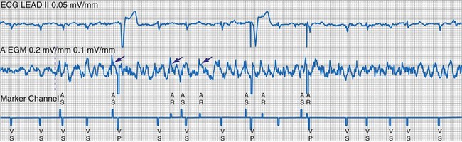
The telemetered EGM has been effectively used to diagnose native arrhythmias, in which the pacemaker is simply an innocent bystander, or to identify retrograde P waves not visible on the surface ECG. The latter ability may facilitate programming of the PVARP to prevent pacemaker-mediated tachycardia.35–43 The telemetered EGM provides clues to why episodes of undersensing may be occurring, including splintering of the EGM and low slew rates, which may place the signal outside the tight constraints of the pacemaker’s sense amplifier, despite an adequate peak-to-peak amplitude44 (Fig. 29-11).
The telemetered EGM can also be monitored periodically to follow the progression of the patient’s intrinsic disease process. A decrease in the amplitude of the telemetered EGM was reported to identify early rejection effectively in cardiac transplantation recipients; a return to the baseline amplitude correlated with resolution of the rejection process.45 Preliminary work on the signal-averaged EGM, either atrial or ventricular, suggests that it may be helpful in identifying disease in the respective chamber that is beyond the resolution of signal-averaging the surface ECG.46
Limitations of Electrogram Telemetry
The apparently adequate amplitude of the telemetered EGM for sensing does not mean that the pacemaker will sense it. The telemetry amplifier may use filters different from those in the sensing circuit, providing qualitative rather than quantitative data on the EGM (see Fig. 29-11). In most pacing systems, telemetered EGMs also have limitations similar to those of event markers. EGMs are real-time recordings and cannot be retrospectively provided by the programmer to facilitate the interpretation of an earlier ECG.
Real-time telemetry allows the physician to analyze the behavior of the pacing system when the patient is in the physician’s office or clinic while these diagnostics are being accessed with the programmer. This is impractical over a long period. In addition, it does not allow the patient to move around much while these recordings are being obtained. Long-term monitoring of pacing system behavior requires a Holter monitor, a loop memory recorder, or event counter telemetry, depending on the desired degree of precision. Pacemakers with microprocessors and significant random access memory (RAM) can now store select EGMs,47,48 as well as event markers, when triggered by the patient or by a predefined set of circumstances. This may greatly reduce the need for Holter or other monitoring techniques to evaluate intermittent symptoms in patients with pacemakers.
Event Counter Telemetry
The first use of stored diagnostic data in cardiac pacemakers was associated with the introduction of multiparameter programmability. Simple data using codes to identify implant indications and medications could be downloaded into the pacemaker for retrieval at subsequent follow-up evaluations. This ability has been expanded, allowing entry of free text (date of implantation, lead model numbers, pharmacologic regimens, and acute implant measurements, including capture and sensing thresholds and lead impedances; see Fig. 29-1, B). This information is printed with the programmed parameters each time the pacemaker is interrogated.
Total System Performance Counters
The simplest systems keep track of the number of times a pacing stimulus is released or a native complex is sensed. This allows for an assessment of the degree to which the pacemaker was used by calculating the percent pacing in each chamber. A refinement of this ability allows the pacemaker to diagnose bradycardia and, in the dual-chamber modes, to determine whether the bradycardia was the result of sinus node dysfunction or AV block. Event counters with this ability have also been termed diagnostic data, implanted Holter systems, and data logging.49–55
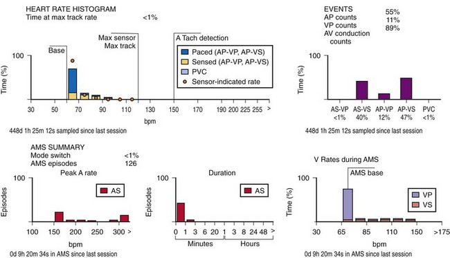
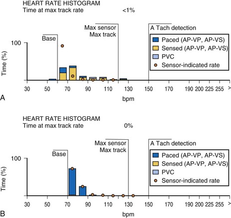
This information may be collected in conjunction with events occurring in specific rate bins, allowing for a detailed report of heart rate distributions. Additional data collected include the percentage of pacing in the atrium and ventricle, length of time at the maximum tracking rate, and the number of episodes in which the pacing system reached the programmed upper rate limit (Fig. 29-12). Additional data may be recorded regarding mode-switching events, pacemaker-mediated tachycardia (PMT) termination algorithm use, or the number of times any one of several other special features was activated. The counters are able to continue to accumulate data until one of the pacing state bins is full and cannot accept additional information. At this point, one or more of the counters are frozen. The volume of data that can be stored depends on the memory capacity of the pacemaker that is dedicated to these features.
Storing a simple marker of the pacing state and rate requires relatively little memory compared with storing waveform data representing the rhythm, as depicted by a consecutive series of EGMs. A theoretical 100-Hz bandwidth with 200 samples per cardiac cycle at eight bits of resolution per sample, recording the entire rhythm during a 24-hour period, would require 140,000,000 bits/day, even if the heart rate was a steady 60 beats per minute (bpm).47 Most implantable defibrillator systems store a series of EGMs preceding and following the delivery of antitachycardia therapy. Premium pacing systems use certain triggers to initiate EGM storage. These triggers may be a high atrial or a high ventricular rate, initiation of mode switching, or activation of any of several other specialized algorithms. Storage may also be triggered by application of the magnet or use of a simple transmitter device by the patient when symptoms are present. An early method to save memory was to provide “snapshots” of representative complexes; the trigger to store these data in an ICD was delivery of antitachycardia therapy. Extensive storage of cardiac rhythm data within pacemakers became possible with increasingly sophisticated data compression algorithms and more memory than previously available. Higher-bandwidth data transmission channels are required for this volume of data storage, particularly for long series of rhythms, so that transmission can be accomplished as efficiently and as quickly as possible.
When the additional ability to monitor a series of rates and pacing states is added, chronotropic function can be assessed by the distribution of atrial sensed rates (AS-VS or PR and AS-VP or PV; see Fig. 29-12). Furthermore, atrial pacing at rates above the programmed base rate reflects sensor drive in the DDDR pacing systems, providing an overview of the sensor behavior. The ability to report both rates and pacing states can provide the clinician with a better insight into the cause of PVEs as well as overall pacing system function. True premature ventricular contractions tend to occur at short coupling intervals, which is equivalent to a rapid rate. Large numbers of PVEs might suggest recurrent ventricular arrhythmias.56,57 If there are large numbers of PVE counts at relatively low rates, the clinician should consider episodes of atrial undersensing or accelerated junctional rhythms, which would also fulfill the pacemaker’s criteria for a PVE (i.e., a sensed R wave not preceded by an atrial event).
Subsystem Performance Counters
An increasing number of specific algorithms and capabilities are used either intermittently or potentially independently of the functional performance of the pacing system. An early counter representative of this capability is the sensor-indicated rate histogram, which reports the distribution of pacing rates that would have occurred had the sensor been totally controlling the pacing rates.58,59 This counter reports the sensor-defined rates, even if the pacemaker was inhibited by a faster native rhythm or the actual functional rate was being controlled by the sensed atrial activity (Fig. 29-13).
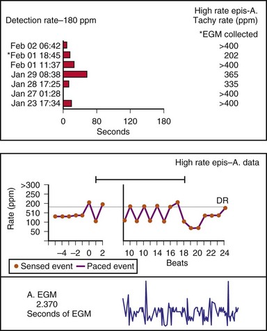
Other subsystem performance counters include automatic mode switch histograms, reports of the cumulative length of time for which the system functioned at MTR, number of times the PMT algorithm was enabled, high atrial or ventricular rate episodes (Fig. 29-14), and sudden rate-drop episodes. These diagnostic counters provide detailed information about the use of a specific algorithm or system behavior that is not activated daily or is not visible on the ECG, making identification difficult using standard recording techniques such as a Holter monitor.
The principal limitation associated with the two types of counters so far described is that counts are placed in a bin, either the pacing state alone or the pacing state and rate, which provides a one-dimensional view of the system’s behavior. If the period of monitoring is short, as during a casual or brisk walk, the clinician can reasonably assess the behavior of the pacing system. Longer periods of monitoring accumulate and overlap the results of many activities. This precludes an assessment of the pacing system’s behavior during a specific activity, or the identification of a symptomatic episode occurring at an earlier time. The ability of the system to store pacing state and rate data with respect to time (i.e., time-based event counters) has been variably termed event record or pacemaker Holter systems.60–62 Technically, this is not yet a true Holter monitor, because continuous rhythm recordings are not retained in memory, even though rate data may be available.
Time-Based System Performance Counters
The other option is to collect the data continuously. As the counters fill, new data are added at the expense of the oldest data (Fig. 29-15). This has been called rolling trend, final trend, or continuous data storage and is based on the “first in, first out” (FIFO) principle. When the patient is seen in follow-up, the data acquired over the time immediately preceding the interrogation of the system are available for review. The patient can often recall symptoms and activities during this period. These can be correlated with the behavior of the pacing system at the time of the symptoms. In this manner, the clinical staff caring for the patient may further assess chronotropic function, the behavior of the pacemaker during a variety of special or usual activities, and whether the sensor and other algorithms are behaving appropriately. The clinician may gain insight into the cause of palpitations and other symptoms that may have occurred during this time by correlation of the recorded data and the patient’s complaints or activities.51,58–62
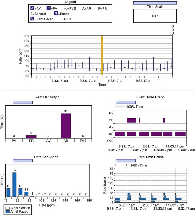
Figure 29-15 Event record display.
Display is from a Pacesetter Trilogy DR+ Model 2364 (St. Jude Medical).
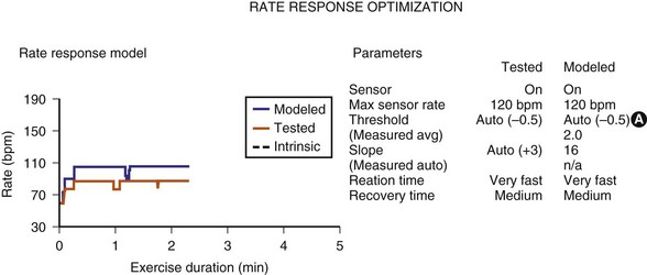
Sensor-input data have been combined with the actual rates achieved to facilitate reprogramming of the sensor parameters. Once acquired, the data from an exercise session are retained in the memory of the programmer, uploaded to the programmer, and then displayed on a screen. The system’s performance is based on a given set of sensor parameters that were in effect at that time. Because the pacemaker has the actual sensor-signal data, it can calculate how the unit would perform in response to a different set of sensor parameters. If a new set of sensor parameters is entered into the programmer, the curves that were based on the original input data are redrawn to display the system’s projected behavior in response to the new set of parameters. The clinical staff can then determine the best sensor parameters for the individual patient without having the patient perform repeated activities (Fig. 29-16). This feature has been termed redraw,63 exercise test, or prediction model.64
Limitations of Event Counter Telemetry
With respect to pacing, a rhythm that is predominantly composed of AV- or PV-paced complexes does not necessarily indicate complete heart block. It might result from a programmed AV delay that was not sufficiently long to allow for full conduction through the AV node. Although the ventricular complex could have been fully paced, it could also have been a fusion or pseudofusion beat. The counters cannot differentiate between these complexes, because the native complex had not yet been sensed, the timer had been completed, and an output was delivered. Another situation would be a total loss of ventricular capture with intact AV nodal conduction (Fig. 29-17). The first conducted R wave in this figure would not have been sensed, because it occurred during the refractory period that followed the ventricular output pulse. An identical result in the counters would occur with intact AV nodal conduction but with ventricular undersensing.
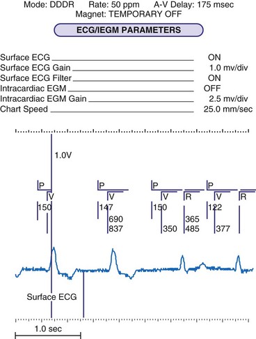
Figure 29-17 Telemetry data limitations.
Data from Pacesetter Synchrony II Model 2022 dual-chamber pacing system (St. Jude Medical CRMD, Sylmar, Calif.)
The event counter data cannot be adequately interpreted without knowledge of how these data are collected, the clinical status of the patient, and any unique behavioral performance of the implanted pacemaker. This is illustrated by Figure 29-14, which is an atrial high-rate graphic from a Medtronic Thera DR pacemaker. The reported rates were greater than 200 bpm, yet the graphic suggests that these were atrial paced events and that the device is not capable of being programmed to rates this high. It is essential to know how the manufacturer calculates rates. In this case, the device measures the interval between atrial events; if the event preceding the atrial output occurred during the refractory period (labeled AR by the markers), the reported atrial paced rate would be based on the AR-AP interval. With this knowledge, the graphic report can be understood. If this fact were not known, the graphic would suggest a pacing system malfunction.
Atrial fibrillation (AF) is a major clinical problem that is common in patients with cardiac implantable electronic devices (CIEDs). Management can be improved by knowing whether AF is present, the frequency of AF, and the duration of AF episodes. Knowing these data allows the clinician to determine the need for antiarrhythmia therapy, for ventricular rate–slowing medication or interventions, or for anticoagulation. Several diagnostic counters are available to assist in the management of AF (Fig. 29-18). These may consist of the number and duration of the episodes, atrial rates and ventricular rates during the episodes, and specific dates and times so that patient symptoms can be correlated to events.
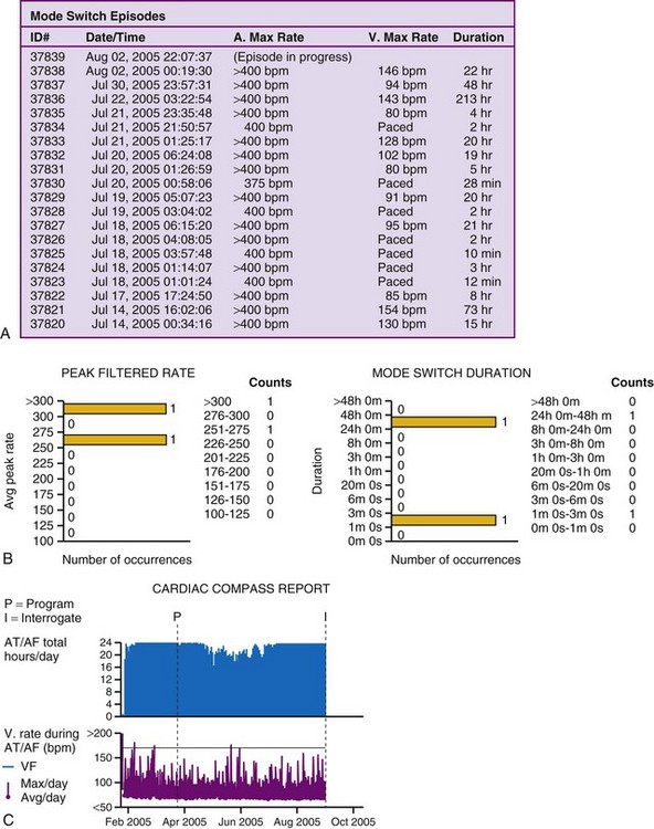
The one caution in terms of accepting data from these counters is the possibility of oversensing in the atrial channel, which would cause inappropriate assignment of events to these diagnostics. The most common cause of false information is sensing of the far-field QRS complex by the atrial lead (Fig. 29-19). This leads to double-counting of the heart rate and incorrect classification of the event as atrial high rate. Use of stored EGMs to verify the cause of the high-rate episode is advised whenever possible, to avoid inappropriate treatment for nonexistent AF.
 Pacing System Malfunction
Interrogating the pacemaker about programmed parameters and measured data, retrieval of any and all event count data, and the use of the event markers and EGM telemetry capabilities are essential in a routine office-based follow-up evaluation. It is even more important when evaluating a suspected pacing system malfunction. Knowledge of the present programmed settings, combined with the baseline data with which the current results can be compared, is crucial. Many devices have special programming features and idiosyncrasies that may appear to be malfunctions to clinicians who are not completely familiar with the particular system under scrutiny. It is not unusual to hear about devices being explanted and returned to the manufacturer for failure to pace at the programmed rate, only to find that hysteresis had been enabled. This is only one of many examples of “pseudomalfunctions,” as discussed later.65–69
Historical Clues
The first step in the evaluation of the patient with a suspected pacing system problem is to gather as much information about the patient as possible (Box 29-1). This includes the indications for the pacemaker, the operative record of the implantation, the model, and possibly the serial numbers of all portions of the implanted pacing system. In addition, one must obtain the current programmed parameters and all measured data. The programmed parameters and measured data are crucial to the correct evaluation of the device.
Box 29-1
Patient Evaluation for Potential Pacing System Malfunction
The full analysis of a suspected pacing system malfunction is facilitated by access to telemetry and programming information, allowing a detailed noninvasive evaluation. Despite this, an invasive evaluation may sometimes be required (Boxes 29-2 and 29-3). The model numbers of the pulse generator and leads should be determined before an invasive evaluation of the system is performed. There may be unique device eccentricities that are known to the manufacturer. In some cases, unique tools or replacement devices may be required. It is therefore wise to contact the manufacturer’s technical service group before an operative intervention for an unexpected behavior in an otherwise clinically stable patient.
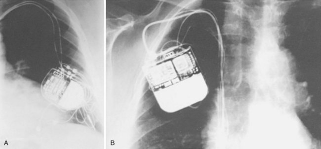
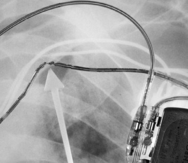
In the absence of an ID card, model and serial number information may be obtained from the operative report or from adhesive labels (provided with each pulse generator and lead) if they were included in the medical record at the time of implantation. If none of these is available, a radiograph of the patient that includes the area of the pulse generator allows the clinician to match the identification label inside the pulse generator to those in a reference source70–72 (Fig. 29-20). Although not all pulse generators have these labels, many have a distinct radiographic “skeleton” or radiopaque alphanumeric labels from which the clinician can determine at least the name of the manufacturer, if not the model. All manufacturers provide toll-free numbers that the clinician may call to obtain further information regarding the pulse generator and the implanted leads.
All manufacturers’ programmers are capable of automatically identifying the model and serial number of their pacemakers and ICDs. Unfortunately, only the programmer from the manufacturer of the pacemaker or ICD can communicate with that device. Certain pulse generators are also capable of storing data concerning the patient, implantation date, and lead model (see Fig. 29-1, B). These data need to be downloaded into the pacemaker by the clinician or support staff. If the pacemaker and programmer have this capability, the programmer provides much of the data necessary for finding additional patient data. It may be possible to obtain further information from the manufacturer’s patient-tracking database.
Knowing the specifics of the implanted pacing system’s components is a crucial first step. It is also important to know if any special considerations apply to the device. These might include recalls, alerts, known idiosyncrasies, and the functions of specialized programmable features and rate-modulating sensors.73–79 Any of these may affect the observed behavior and help guide further evaluation of the system, as well as any parameter adjustments. For example, a pulse generator exhibiting its elective replacement parameters would typically be replaced using the same lead system if the system had a good capture threshold, a good sensing threshold, and a normal stimulation impedance. If the lead is under a safety alert or recall, however, the clinician should follow recommended guidelines and, if appropriate, replace the vulnerable lead system at the time of generator replacement. Some patients have required a second procedure to revise another element of the pacing system simply because the implanting physician was unaware of previously reported potential product deficiencies.
Physical Examination and Telemetry
The precordium is inspected for chest wall or diaphragmatic stimulation; the latter may indicate several possible problems (Box 29-4). If the system is unipolar, the pacemaker (if coated on one side) may have the anode facing the skeletal muscle or may be considered to be upside down in the pocket. The malpositioning of a pacemaker sitting upside down in the pocket may have occurred inadvertently at implantation, may have developed spontaneously (most often with lax subcutaneous tissues), or may have resulted from the patient’s manipulating the pacemaker within the pocket, a condition known as twiddler’s syndrome.80–84 Alternatively, the unidirectional insulated coating on the pulse generator or the grommets protecting the set screws may have been damaged or may have degraded over time. In some situations, pocket stimulation may occur even with the generator in the correct position and the insulation intact.85 Also, most pacemakers now produced have no coating on one side and therefore are “omnidirectional” with respect to their placement in the pocket. High-output settings, placement in or below the pectoral musculature, or high-current delivery as a result of low lead impedance may also be at fault. Outer lead insulation failure may also allow problematic current leakage and local extracardiac muscle stimulation.
The neck veins should be evaluated for distention or the presence of cannon A waves. The latter might indicate an atrial lead problem, inappropriate programming in a dual-chamber system with too long or too short an AV delay assuming otherwise normal electrical function, or pacemaker syndrome in a single-chamber system. Auscultation of the heart for variable-intensity heart sounds, rubs, or gallops may also give clues to the physiology related to the patient-device interaction.86,87
Physical maneuvers may be useful to unmask an intermittent symptom or malfunction during examination. Carotid sinus massage and other vagal maneuvers may slow the intrinsic rhythm so that device function or malfunction becomes evident. Positional changes (sitting or standing up) or having the patient perform in-place exercise or isometric maneuvers may accelerate the heart rate to allow observation for sensing (proper tracking and inhibition). Manipulation of the device and lead may disclose an intermittent lead fracture, loose connection, or insulation failure that was not evident while the patient was lying quietly on the examination table. Other helpful maneuvers include movement of the patient’s ipsilateral arm (reaching overhead, across the chest, or behind the back), isometric exercise (pressing the hands together in front of the chest or reaching around the chest to scratch the opposite side), and doing sit-ups (in the case of an abdominal implant) are helpful in identifying an intermittent problem.88,89 If the patient develops symptoms during the induced abnormal behavior and these symptoms reproduce those that occurred spontaneously, the cause of the symptoms likely has been identified.
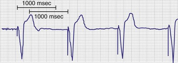
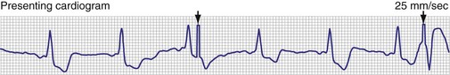
A 12-lead ECG is required to document the pacemaker-evoked morphology of the atrial and ventricular depolarizations at baseline. It may then be helpful to repeat a 12-lead ECG, or at least a multiple-lead ECG, instead of a single-lead rhythm strip, when evaluating a suspected malfunction. A myocardial infarction or progressive cardiomyopathy may have occurred, resulting in a change of capture or sensing thresholds. A change in the paced QRS axis may be a clue to lead dislodgment or loss of capture from one lead in a biventricular system, whereas a change in the intrinsic axis (a new bundle branch block) may be associated with sensing problems. Multiple ECG leads are frequently necessary to recognize the relatively low-amplitude atrial depolarization. In addition, the pacing artifact may not be visible in any given lead, especially if the pacing system is bipolar90 (Figs. 29-21 and 29-22). Care should be taken in the interpretation of the ECG tracing with regard to the type of recording system used. The older-style analog systems provide a consistent reproduction of the pacing stimulus, varying the relative amplitude of the stimulus with the delivered energy of the system. An unstable paced artifact on an analog ECG is a sign of potential problems. The same cannot be said for digital recording systems, which have generally replaced the older-generation analog systems. Although these allow computer interpretation of the ECG, they can introduce many artifacts and have several idiosyncrasies that have been misinterpreted as a device malfunction when they were actually recording system artifacts90–96 (Fig. 29-23). In many cases, the pace artifact is not visible in any lead.
The initial action should be interrogation and printing of the programmed settings.97,98 The printout is important because it documents the initial settings and serves as a reference should the clinician want to restore the device to the same settings after the evaluation is complete. Although most programmers have a “return to initial settings” capability, if the programmer is turned off or inadvertently disconnected from the power source, these data will be lost. Virtually all currently implanted pacemakers have the ability to measure and monitor critical system functions. These data should be interrogated and printed. The same recommendation holds for models that have extensive histograms, trend data, or other diagnostic counters. If the settings are routinely retrieved at the beginning of the evaluation, the various programming changes that may be required during the evaluation and that may cause clearing of these counters will not result in loss of critical data. Indeed, on completion of this task, the counters should be cleared so that they reflect the subsequent behavior of the implanted pacing system in response to any changes made by the end of the evaluation. Some devices automatically clear the data 1 hour after the end of the programming session, or when the final report is printed. Others simply use the FIFO data storage scheme, with the newest events written to memory and the oldest deleted.
When reviewing the results of the interrogation, an evaluation of the programmed setting data should be the first step. What are the mode and base rate? Are any special algorithms enabled? Many suspected device malfunctions are eliminated once the programmed parameters become known. These may have been changed by another medical professional since the last evaluation, or they may have been entered incorrectly into the patient’s record, accounting for the concern. The former situation has been referred to as phantom reprogramming, which most often occurs when another clinician does not notify those responsible for monitoring the patient about the changes made to the pacemaker. Depletion of the battery may also cause a change in the mode, rate, or other parameters. Box 29-5 lists other causes of mode changes. Some dual-chamber devices change to a single-chamber mode to conserve power if the battery’s voltage drops below a manufacturer-defined value. In other devices, the sensor, data storage, and telemetry may be disabled to slow the rate of battery depletion, in an effort to protect the patient from a no-output state.
Box 29-5
Causes of Apparent Mode and Parameter Changes
New devices that are shipped or transported via areas experiencing winter weather may cool sufficiently to allow the battery’s voltage to drop, triggering the elective replacement behavior even though the device is new. Normal function either spontaneously returns or can be reset using the programmer once the device has warmed up to at least room temperature. Attempting to accelerate the warming of the pulse generator by placing it in an oven may damage the pacemaker. Electrocautery and defibrillation can cause mode and polarity changes to occur on some models and may also trigger the elective replacement indicator of the pacemaker. Pacing rate changes may also occur for many other reasons (Box 29-6). Therefore, no assumptions about the expected operating characteristics of a device can be made without the knowledge of the mode and rate.
Box 29-6
Causes of Rate Change
The measured data are reviewed.5,44,99 Stimulation impedance for each lead is one of the most important elements of the measured data. Proper interpretation of lead impedance, however, depends on the manufacturer and model of the lead used, the method of measurement, and the historical values of an individual lead’s impedance. The other parameters of the lead’s performance, including pulse voltage, pulse charge, pulse energy, and current, should also be correlated with the measured impedance, and internal consistency assessed. A marked discrepancy between observed and expected values may identify a telemetry error or measurement error within the pacemaker rather than a primary problem with the lead. It is prudent to repeat the measurements several times if a conflict is noted.15 Some devices take periodic readings of stimulation impedance and graph these over time (see Fig. 29-5). This is a highly effective tool to spot changes in a lead system.
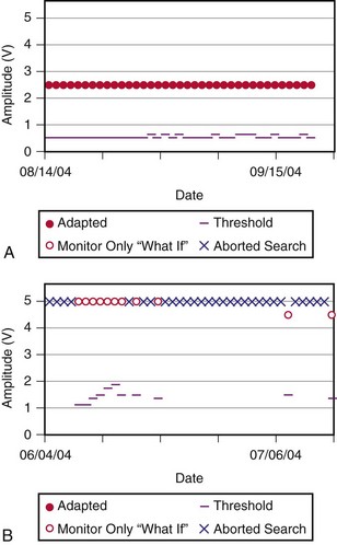
After the telemetry and measured data have been obtained and reviewed, a meticulous assessment of the pacing and sensing thresholds is warranted. A complete threshold evaluation should be performed for each lead present. Pacemakers that have automatic algorithms to regulate output should have their diagnostics evaluated for abrupt onset of changes or great variability (Fig. 29-24). Marked changes in capture or sensing thresholds may imply malfunction of a lead or of the lead-tissue interface when lead impedance values are stable. Other causes of both permanent and transient increases in threshold are discussed later.
If a pacing system problem is suspected, posteroanterior (PA) and lateral chest radiographs should be obtained. In the “predigital” radiology era, it was best to request a slightly overpenetrated exposure to visualize the intracardiac segment of the pacing leads for position and integrity. A thoracic spine exposure technique provides optimal penetration for visualization of the pacing leads. Most radiology departments are digital, allowing manipulation of the brightness and contrast on a computer display. The radiograph should be inspected for evidence of conductor disruption; insulation failure, as inferred from a deformity in the conductor coil, because the insulation is radiolucent (Fig. 29-25); proper lead placement in the generator connector block, adequate slack in the lead system, electrode perforation, dislodgment or malposition of a lead, generator movement, and proper orientation of the coated side of the can positioned against the muscle (i.e., leads exiting in a clockwise direction, except in devices specifically designed for implantation on the left side of the chest or devices that are not coated; see Fig. 29-20).100 The latter criterion is especially important when evaluating pocket stimulation in unipolar systems or devices programmed to the unipolar pacing polarity. Because most new pacemakers and all ICDs are uncoated, leads may exit in a counterclockwise or clockwise manner, which can be confusing if the construction of the pacemaker is not known. Knowledge of the design of the specific pacemaker, lead, or adapter in question is essential to establishing the proper diagnosis. Close attention should be paid to the infraclavicular area, where pressure from structures around the clavicle and first rib can cause lead failure.101–115
Differential Diagnosis of Pacing System Malfunction
Failure of Output (No Artifact Present)
In the pacemaker-dependent patient, failure to pace represents a potentially catastrophic and lethal situation. The ECG appearance in a single-chamber system is that of no pacing artifact when the intrinsic rate is below the lower rate limit of the device. This may be intermittent or continuous. In a dual-chamber device, the clinician may see an atrial pace alone, ventricular pace alone, or no pacing artifacts at all. Of course, any of the latter may be entirely normal depending on the patient’s sinus rate, AV nodal conduction, A-V interval settings, enabling of hysteresis or one of its analogs such as sleep mode or rate-drop response, and sensor settings. Box 29-7 lists the causes of a no-output condition. In evaluating this situation, the clinician must be certain that a malfunction truly exists before taking any corrective action. Remember that the ECG (especially as visualized in a single surface lead) may not display the pacing artifact because of technical factors (Fig. 29-26). This is particularly common in bipolar systems and systems programmed to a lower-than-nominal voltage output. It is important to recognize that the problem may be failure to capture rather than failure to output. Access to telemetered event markers and measured data facilitates the evaluation. Event markers identify the release of an output pulse or recycling resulting from a sensed event, even if this is not visualized on the ECG. If lead impedance is normal (with the previously noted caveat that the problem may be intermittent and multiple measurements should be obtained), this probably reflects a capture problem if there is an output, or an oversensing problem if there is a sensed event. A high impedance suggests an open circuit, whereas a low impedance suggests an insulation failure. Both are probable mechanical problems with the lead in a chronically implanted system. In a newly placed system or when the leads have been recently replaced into the pacemaker, this may be caused by malalignment of the lead in the connector, a loose set screw, or failed spring-loaded connector.
Box 29-7
Failure to Pace (No Output or Rate Slowing)
PVARP (postventricular atrial refractory perioda) algorithms
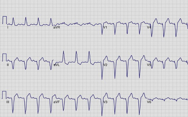
Figure 29-26 12-lead ECG of patient with normally functioning bipolar pacing system.
Note that a small pace artifact is seen in lead V4, whereas other leads do not show it at all.
If the markers fail to demonstrate an ineffective output or an inappropriate sensed event, normal function (e.g., hysteresis) should be considered. At this point, the programmed parameters should be double-checked to determine whether hysteresis or one of its analogs was programmed. Pacemakers have been returned to their manufacturers as defective when hysteresis was enabled. In these cases, the physician was either not aware of the programming or did not understand this feature.112–114 Other causes of intermittent prolongation of the pacing interval are listed in Box 29-7.
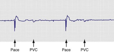
Another source of evaluation error is failure to recognize intrinsic complexes that are present and are properly sensed, causing an appropriate device inhibition. This problem may occur in the hospital’s telemetry unit, where only a single lead is monitored. Premature beats may be present, with the ectopic complexes appearing nearly isoelectric (Fig. 29-27). Although the observer may not recognize the PVC or premature atrial contraction (PAC) on casual observation, the pacemaker senses these events and is appropriately inhibited. The use of multiple leads or a 12-lead ECG recording virtually eliminates this cause of pseudomalfunction.
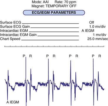
The most common cause of lack of an output pulse in unipolar systems is oversensing. The pacemaker, for all its complexity, operates from a relatively simple set of rules. Any event that generates an electrical signal of adequate strength and frequency content (during the alert period) is sensed and resets the timing cycle. Oversensing is the sensing of a physiologically inappropriate or nonphysiologic signal. A cause of intracardiac oversensing in AAI systems is sensing of the far-field QRS complex116 (Fig. 29-28). This is most common in unipolar systems when the lead is placed close to the tricuspid valve, with high atrial sensitivity settings, and with short atrial refractory periods. In systems that can deliver antitachycardia pacing (ATP) therapy, oversensing may result in an inappropriate diagnosis of a tachycardia and therapy delivery.117 In dual-chamber systems, atrial far-field sensing is also one of the most common causes of inappropriate mode switching, because the pacemaker is seeing double the actual heart rate. Far-field sensing of the atrium is uncommon in VVI systems because of the diminutive size of the P wave, as seen electrically from the ventricle. Although reported, it is usually associated with other problems, such as an insulation abrasion on the atrial portion of the ventricular lead.15 Sensing of the intracardiac T wave may occur in VVI systems with similar results (Fig. 29-29), although this was a more common problem in the early days of pacing, as was oversensing of the polarization artifact generated by the output pulse. Other chapters in this text provide a description of polarization and the evoked response. Oversensing of this event occurred with short refractory periods combined with high outputs on certain lead systems. This has also been reported in ICD systems that require short refractory periods and broad band-pass filters in the sense amplifier.
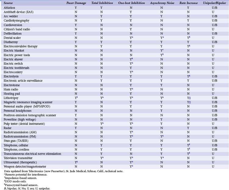
The most common source of a physiologic extracardiac signal that causes oversensing is myopotential inhibition. The pacemaker is capable of sensing muscle depolarizations—not only those of the heart, but also those of noncardiac structures such as the pectoralis, rectus abdominis, and diaphragmatic muscles. Myopotential inhibition of pacemaker output can be seen during arm movements (pectoral implantation) or when the patient sits up or does a Valsalva maneuver (abdominal implantation; Fig. 29-30). This occurs primarily in unipolar systems, because the anode, the pacemaker’s case, remains in proximity to these muscular structures.88,89,118–124 Nonphysiologic electrical signals may also cause oversensing. Formerly, electromagnetic interference (EMI) from microwave ovens was a significant problem when pacemakers were encased in plastic or epoxy, with the relatively large antenna created by the discrete components. Newer devices are shielded from EMI by their metal cases and filters. Integrated circuits provide for a smaller antenna, although strong EMI sources can still cause oversensing. Table 29-1 summarizes EMI sources and their potential effects.125–142
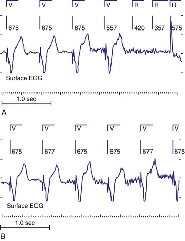
It has been well documented that intermittent metal-to-metal contact can create electrical signals. These make-break signals may be of sufficient amplitude to be detected by pacing systems. Signals exceeding 25 mV have been recorded in some cases (Fig. 29-31). These large signals present a major problem: the false signal cannot be managed by programming the device to a less sensitive setting, because the nonphysiologic signal is far greater than the physiologic atrial or ventricular depolarization. The sources of these electrical signals include a loose set screw, fracture of the conductor coil, failed insulation between the anode and cathode conductors in a bipolar system, interaction between active and abandoned pacing electrodes, and a loose retractable fixation screw.142–150 Other mechanisms can also cause these signals, such as capacitance between the anode and cathode of a coaxial bipolar lead with failing insulation.
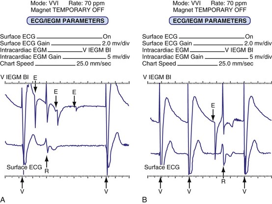
Oversensing can be confirmed by use of the magnet or by reprogramming to an asynchronous mode. If the cause of the pauses or slow rate is oversensing, regular pacing will resume during asynchronous pacing. If a lead failure, open circuit, or other cause exists as the cause of lack of output, these maneuvers will not result in consistent asynchronous pacing. The use of EGMs and event marker telemetry can quickly identify the cause of the pause, whether an output pulse that failed to reach the heart or the presence of oversensing. In the case of oversensing, the telemetered EGM may provide a clue to the source of the extraneous signal. As demonstrated in Figure 29-30, this is useful for differentiating the causes of oversensing and deciding on the proper remedy. The normal refractory period timing cycle initiated by the oversensing may give the overt appearance of undersensing, because the native complex that coincides with the electrocardiographically invisible refractory period is not sensed (normal behavior), allowing for time-out of the pacing escape interval and delivery of an output pulse; this is termed functional undersensing (see Fig. 29-4). The output pulse, if delivered during a period of physiologic refractoriness initiated by the native cardiac depolarization, may not capture, a phenomenon appropriately termed functional noncapture (Fig. 29-32). The true cause of the observed behavior is readily appreciated with telemetered event markers, but it may be difficult to decipher from the freestanding ECG or rhythm strip.
Primary component failure of the pulse generator circuit is the least common of all the causes of pacing system failure, but it too can result in failure to output (Box 29-8). Patients who have been lost to follow-up may present with complete exhaustion of the power source (battery) and a completely inoperative and unresponsive system. As the power source begins to fail, slowing of the pacing rate and erratic behavior may occur (Fig. 29-33). This may also be associated with mode and rate changes with or without sensing problems.
Several problems may be mistaken for pulse generator failure, resulting in a no-output situation. These are generally related to problems at implantation. If the lead is not positioned properly in the connector block of the pacemaker, or if an improper lead is used, the electrical connection may not be complete. This is still an open circuit, but in the presence of a technically normal pulse generator and normal lead. The two are simply not connected appropriately, which is a physician error at implantation. A transient situation has been reported in unipolar systems after wound closure. Air may be present in the pocket, especially if a large generator is replaced by a smaller one. Air is an effective insulator and prevents contact of the anterior anodal surface of the pacemaker’s case with the body’s tissues (this applies only to coated pacemakers). The result is an incomplete circuit until the air is absorbed. Subcutaneous emphysema has also been reported to be responsible for loss of anodal contact.151,152 A similar pseudofailure occurs when a unipolar pulse generator is out of the pocket. If the stimulation impedance could be measured in each of these settings, it would be extremely high and well above the standard measurement for the particular lead being used. Event markers would report the release of an output pulse, even though the circuit was open, precluding effective pacing.
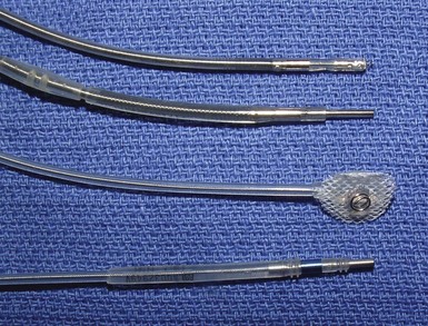
It is important to keep in mind that virtually all bipolar pacemakers may be programmed to function in the unipolar mode. Failure to output may also be seen with bipolar pacemakers that are connected to a unipolar pacing lead when programmed to pace in the bipolar polarity. This is more likely with IS-1 leads because the bipolar and unipolar connectors may appear identical. Most unipolar IS-1 leads have a protective metal band where the anodal screw of the pacemaker connector block is located to prevent inadvertent tightening of this screw from damaging the lead. This gives the appearance of a bipolar lead, even though no anodal conductor is present, and may be misleading (Fig. 29-34). Most polarity-programmable pulse generators allow the user to designate the lead type as “unipolar” in a separate field of the programming system. Then, when the standard programmed parameter page is accessed, the “bipolar” lead option is locked out, minimizing the chance that the device will be accidentally programmed to the bipolar configuration. Of course, this lockout feature only works if the lead type is programmed correctly. Some newer devices have the ability to verify that a bipolar circuit is present before allowing permanent programming to be completed to the bipolar polarity. This feature operates independently of any programmed lead type and also protects against programming to an ineffective polarity if the anode has failed because of lead fracture, malalignment of the lead in the connector, or failure to secure the anode set screw.
Failure to Capture (Artifact Present)
With the advent of the newer ECG recording systems and the use of pulse artifact enhancement, the clinician must first be certain that the pace artifact seen is truly from the pacing system. The newer recording and monitoring systems have pacemaker pulse detectors that, when enabled, generate a discrete pacemaker pulse artifact in response to any high-frequency transient. Many extraneous signals can cause the enhanced ECG, telemetry system, or Holter recorder to place an erroneous pace artifact on the ECG. EMI (including programmer telemetry), loose ECG electrode connections, and subthreshold pulses, as seen with the minute ventilation sensors associated with normal pacemaker function, are examples of situations associated with spurious ECG artifacts (see Fig. 29-23). The use of event marker telemetry and EGMs can assist in differentiating the true pacemaker output from a recording system artifact, whereas retrospective analysis of a recorded rhythm may prove challenging.
A common cause of functional noncapture is undersensing, with a resultant delivery of the pacemaker impulse during the physiologic refractory period of the myocardium. Although the output does not elicit a depolarization, the problem in this case is related to sensing, not output, and should be evaluated as such (see Fig. 29-32). This is best identified as undersensing, but if one insists on commenting on capture, it is functional noncapture. No matter how high the energy content of the output pulse, the myocardium is physiologically refractory and incapable of being depolarized.
Box 29-9 lists the causes of noncapture. The onset of noncapture in relation to implantation of the device and lead system can provide valuable clues to the cause. Loss of capture shortly after lead implantation suggests dislodgment, malposition, or perforation of the heart by the lead. Elevated thresholds that occur during the first several weeks after implantation were more common in the early days of pacing. Although the incidence of this problem has greatly decreased with the introduction of steroid-eluting electrodes and other electrode materials and designs, a significant rise in capture threshold may still occur. The capture threshold rise is attributed to the inflammatory reaction that results from two factors: (1) the pressure and thus trauma applied by the electrode to the endocardium and (2) a standard foreign body reaction. The peak of the early threshold rise usually occurs 2 to 6 weeks after implantation. Use of a higher output during this acute period minimizes the likelihood of noncapture until the threshold improves to its chronic level. Use of newer devices that can measure the capture threshold on a beat-to-beat or periodic basis can reduce the need for these higher outputs, yet provide the safety needed for the patient should the threshold rise. A rise in threshold more than 6 weeks after implantation is usually considered to be in the chronic phase of the lead maturation process. The threshold may rise steadily over time until noncapture occurs or until the threshold exceeds the pacemaker’s maximum output, typically referred to as exit block.153–159 Older lead models and some epicardial leads are more likely to develop elevated capture threshold levels.160–163 Some patients demonstrate repeated episodes of this phenomenon and have required multiple lead revisions or replacements. Children with epicardial implants are especially prone to this condition.153,164 Steroid-eluting leads are useful in minimizing the development of exit block.165–173 Anecdotal reports propose the use of high-dose systemic steroids to lower high thresholds, with dosing continued for months and then slowly tapered, but no prospective randomized trials have evaluated this pharmacologic intervention.174–176
Causes of capture threshold rise occur in both the acute and the chronic phase. Any severe metabolic or electrolyte derangement can lead to acute threshold changes177–188 (Box 29-10). These may occur in critically ill patients or during and immediately after cardiac arrest. Noncapture may occur secondary to the hypoxemia, acidemia, or hyperkalemia, rather than be the primary event leading to the arrest. In addition, some medications may affect capture thresholds, resulting in significant changes from the patient’s baseline189–194 (Box 29-11). Beat-by-beat capture confirmation and periodic capture threshold measurement systems are now in widespread use. These have been reported to identify patients with transient or sustained late rises in capture threshold that would have resulted in loss of capture had the implanted pacemaker been programmed to a standard 2 : 1 safety margin.195 As experience continues using systems with these capabilities, understanding of the factors that can affect chronic capture threshold will increase.
Although the clinician might expect that fracture of a lead would result in the absence of any visible pacing artifact, this is frequently not the case. The ECG may display a pace artifact with failure to capture, especially in unipolar systems. This occurs because the current passes across the gap in the conductor coil through the fluid in the lead; however, the resistance is high, and the delivered current is likely to be subthreshold. In unipolar systems, the anode (i.e., the pulse generator surface) is virtually always intact and provides enough of an electrical transient to trigger the artificial pace artifact circuitry of many monitoring systems. One can also see stimulus artifacts in the setting of a total disruption of both the conductor and the insulating sheath, which allows the output to be delivered to some local tissue, resulting in a stimulus on the ECG even though there is noncapture.145
Latency is a finding that may be mistaken for failure to capture. Latency is defined as the delay between delivery of the pacing impulse and onset of the evoked potential or electrical systole.196 Some antiarrhythmic agents, myocardial disease, or severe electrolyte disturbances (e.g., hyperkalemia) can cause latency (Fig. 29-35). A Wenckebach type of latency prolongation, leading to a noncapture and a repeat of the cycle, has also been reported.
Failure to Sense
To appreciate undersensing, it is necessary to understand how the sense amplifier works and where in the cardiac cycle the sensing can and cannot occur. A prerequisite for proper sensing is a good-quality EGM; the signal must possess both an adequate amplitude and an adequate frequency content (slew rate) to be sensed properly. A signal of apparently adequate peak-to-peak amplitude may be greatly attenuated by the sense amplifier because of its poor slew rate. The resultant “filtered” signal may be of insufficient size to be recognized as a valid event.197–202 Box 29-12 lists the causes of sensing failure.
Box 29-12
Causes of Undersensing
It is often assumed that the pacemaker senses a cardiac event at the beginning or the peak of the P wave or QRS complex, as seen on the surface ECG. This is not the case. The surface P wave or QRS is a summation of all electrical events occurring at the cellular level over a period of time (normally 80 to 120 msec, but may be longer due to conduction system disturbances). The intracardiac EGM as recorded from a pacing electrode appears as a large-amplitude, relatively rapid deflection (see Fig. 29-10). If one did not know that the recording was an EGM, an atrial signal could be easily mistaken for a QRS complex presumed to have been recorded with a standard surface ECG. It is therefore helpful to record both the atrial and the ventricular EGM simultaneously, the EGM with the simultaneous surface ECG, or telemetered event markers (nearly all pacing systems now provide all these simultaneously). This event, the intrinsic deflection of the QRS or P wave, is generated as the wave of depolarization passes by the electrode. This is the complex that is sensed, even if it occurs well after the onset of the native depolarization. An excellent example of this delayed sensing is in the patient who has right bundle branch block and a pacing electrode in the right ventricle. The native depolarization occurs late in the right ventricle because of the conduction delay. The pacemaker does not sense this event until that depolarization reaches the pacing lead, which is very late in the timing of the surface QRS complex. If it is assumed that sensing occurred earlier, this may be incorrectly labeled “late sensing.” Measurements made from the onset of the QRS complex can misinterpret the timing cycle by more than 100 msec. Therefore, an ECG with a pacing artifact in the QRS (pseudofusion and fusion) can occur in the presence of absolutely normal sensing203,204 (Fig. 29-36).
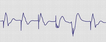
The refractory and blanking periods are integral to understanding sensing and whether a native complex is even potentially capable of being sensed. A blanking period is a time during which no sensing at all will occur on a given channel. A refractory period is similar to a blanking period, but events occurring during a refractory period may be used for purposes other than resetting escape intervals. These “sensed but not used” events can be used by the device to detect noise on a lead, or detection of atrial events for initiation of mode switching. Long programmed refractory and blanking periods can cause undersensing of events occurring within these periods (Fig. 29-37). This might occur in the case of a closely coupled PVC or PAC or very rapid intrinsic rhythms. Although there may be resultant competition, this is not a lead or pulse generator malfunction, in that both are functioning properly and in accord with their design. This is clinically undesirable and reflects inappropriate programmed settings in the pacemaker, a behavior amenable to correction by programming. This is also termed functional undersensing, because the pacemaker is not capable of sensing at the time the native signal occurred. On the other hand, the failure to sense the native complex allows the timing period to complete, with the resultant release of an output pulse that may prove to be ineffective because it was delivered at a time of physiologic refractoriness. Functional undersensing usually results in functional noncapture. A classic example of this phenomenon was the committed DVI pacing system, an early-generation (and now obsolete) AV sequential pacing system that was not capable of sensing on the atrial channel but, with release of an atrial output, was committed to release a ventricular output even in the presence of a native R wave.203,222
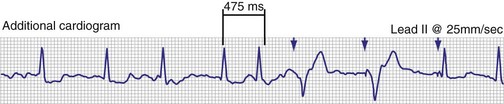
Figure 29-37 ECG rhythm strip showing undersensing of QRS complexes in patient with atrial fibrillation.
As in noncapture, the onset of undersensing in relation to implantation of the pacemaker and lead system may direct the clinician to the correct diagnosis of the malfunction. Undersensing that occurs close in time to implantation should lead the physician to suspect dislodgment, malposition, or perforation of the electrode. Problems occurring in chronic systems are frequently caused by mechanical problems with the lead or, if the lead is normal, by programming errors. Occasionally, problems are attributable to a change in the morphology of the intrinsic cardiac signal associated with myocardial disease progression. Inappropriate programmed settings do occur, particularly when sensitivity threshold testing has been performed in a nontemporary manner during follow-up. The clinician may forget to return the sensitivity to the appropriate setting and leave it at or above the threshold setting. Occasionally, the sensing threshold may show a slow decline in the amplitude of the native signal as the lead-tissue interface changes over time.205–212
The vector of depolarization can affect the amplitude and slew rate of the EGM. Any change in the vector may result in significant changes in the sensing threshold. If a patient with a ventricular pacemaker has a myocardial infarction, develops a bundle branch block, or has PVCs, the intracardiac signal may be insufficient to allow sensing at a previously appropriate setting206–208 (Fig. 29-38). The same may be seen with atrial implants and PACs. Another cause of vector change is movement of the lead’s position associated with respiration. Marked changes in the intracardiac signal can be documented in some patients as the angle of the lead relative to the heart changes with body position or diaphragmatic motion209–212 (Fig. 29-39). Evaluation of the quality of the intracardiac signal associated with sensing failure is greatly facilitated by access to the telemetered EGM.

Figure 29-38 Intracardiac electrogram (ICEGM) and surface ECG (I, II, III) of intrinsic beats and PVC.
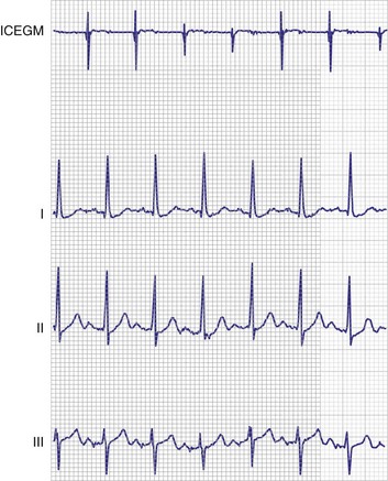
As the pacemaker’s battery begins to become depleted, erratic behavior may occur, including persistent or intermittent undersensing. Failure of a circuit component may also cause sensing failure. Rarely, the reed switch that activates the magnet mode may stick in the closed position, causing (in most cases) asynchronous pacing. For the same reason, when reviewing a rhythm strip, the clinician must know whether the magnet was over the device when the recording was made. Asynchronous pacing may also be seen during the interference or noise mode function of the device. The latter obligates pacing when high-frequency, nonphysiologic electrical signals are sensed by the pulse generator (Fig. 29-40). Typically, this is defined as multiple sensed events occurring within the terminal portion of the ventricular refractory period. The device then paces asynchronously to protect the pacemaker-dependent patient against inappropriate device inhibition.142,213
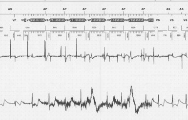
The use of external or internal defibrillation can result in temporary or permanent loss of the sensing function. This may result from transient saturation of the sensing amplifier pacemaker, circuit damage, or lead-myocardium interface damage. This phenomenon occurs when the large electric current delivered by the defibrillator is diverted from the pacemaker’s circuitry to the pacing lead by way of Zener diodes, which are included to protect the pulse generator from large voltage surges. The result may cauterize the myocardium and thereby reduce or eliminate the local EGM. It may also cause a marked elevation in the capture threshold or result in exit block. Capacitive coupling is another mechanism that may allow a current to be induced into the pacing lead, by a defibrillation shock or nearby electrocautery use.214–216 Exposure to magnetic resonance imaging (MRI) may result in inductive coupling with the lead system, induce a current, and cause the same problem.
Dual-Chamber Pacemaker Issues
Crosstalk Inhibition
Crosstalk is a potentially catastrophic form of ventricular oversensing that can occur in any dual-chamber mode in which the atrium is paced and the ventricle is sensed and paced. Consider that the common output voltages for the atrial channel range from 2.5 to 5 V, or 2500 to 5000 mV. The ventricular lead is just several centimeters away from this atrial lead and is “looking” for an electrical event of about 2 mV, which would represent a sensed ventricular depolarization. If the ventricular channel senses the pacing impulse delivered to the atrium, it interprets the event as an R wave. The ventricular output is inhibited, and the patient is left without pacing support. If crosstalk occurs in a patient with complete AV block, ventricular asystole could result. In the absence of an escape rhythm, only paced P waves would be visible.217–220 Conversely, crosstalk is more difficult to detect when AV nodal conduction is intact. In a system that uses ventricular-based timing, the result may be an acceleration of the paced atrial rate with ventricular output inhibition, even in the presence of a first-degree AV block that exceeds the programmed AV delay.220
As demonstrated in Figure 29-41, crosstalk can be recognized by an acceleration of the atrial paced rate in a non-sensor-driven dual-chamber system using ventricular-based timing. Note that ventricular sensing occurs virtually simultaneously with atrial output. The AV delay is immediately terminated with ventricular sensing, and the atrial escape interval (AEI) is started. Therefore, the pacing interval with this type of timing is equal to the AEI (programmed pacing interval minus AV delay) plus the ventricular blanking period. Rate-modulated pacing systems that use ventricular-based timing have a rate acceleration that is seen at the base pacing rate. Crosstalk may not be readily diagnosed in patients with rate-modulated pacing systems and intact AV nodal conduction if the increased atrial pacing rate is believed to be caused by the sensor.
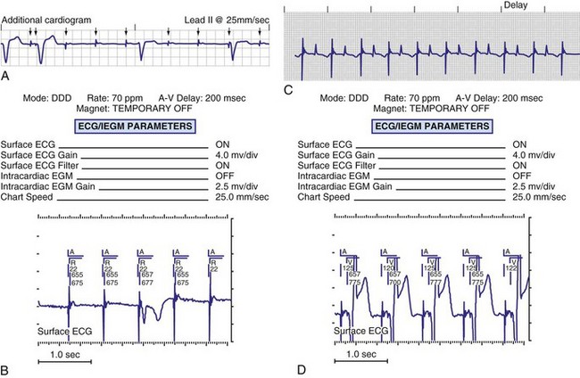
Pacing systems that use atrial-based timing do not exhibit this rate increase. Although ventricular sensing of the atrial output inhibits the ventricular output, the portion of the AV interval not used is added to the AEI, maintaining atrial pacing at the programmed interval (Fig. 29-42). Without access to event marker telemetry, ventricular output inhibition from crosstalk cannot be differentiated from failure to output, as with an open circuit.
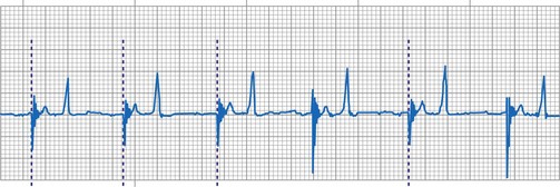
Several factors increase the likelihood of crosstalk (Box 29-13). Programmed settings that make the ventricular channel more sensitive or that increase the atrial energy output predispose to this problem. Insulation failure on the atrial lead also increases the chances of crosstalk by increasing the pulse charge and energy. Certain pacemaker models are more prone to this phenomenon than others, related to differences in circuit designs and the degree of isolation between the two channels within the pulse generator.217 Crosstalk may occur internally, within the circuitry of the pulse generator, as a result of external oversensing between the pacing leads. Unipolar systems are also significantly more prone to crosstalk because of the larger electrical signal, as sensed by the ventricular channel.218–223
Prevention of Crosstalk
The use of an additional ventricular refractory period, known as the ventricular blanking period (VBP), is fundamental to prevention.221 The VBP begins with the atrial output and usually lasts from 12 to 120 msec (the “ultimate blanking period” was the now obsolete DVI-committed mode, during which no sensing occurred on the ventricular channel at any time during the A-V interval after an atrial output pulse). In most devices, this is a programmable parameter. During the VBP, nothing (including the atrial output) can be sensed on the ventricular channel. Short VBPs help to prevent the undersensing of intrinsic ventricular activity but may allow crosstalk to occur. Long VBPs virtually ensure the prevention of crosstalk but may cause intrinsic events to not be sensed, a potential problem if the native beat is a late-cycle PVC and the A-V interval is programmed to a long length. Functional failure to sense a PVC, because the intrinsic deflection of the PVC coincided with the VBP, may be followed by a ventricular output beyond the myocardial refractory period and on the vulnerable zone of the T wave. This might result in the induction of a ventricular arrhythmia, which could also occur with atrial undersensing if a normally conducted QRS complex falls into the VBP. The latter event would not be detected, and an unnecessary stimulus would be delivered (Fig. 29-43).
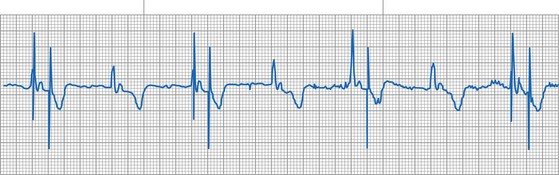
Prevention of Crosstalk Sequelae
The earliest approach to prevention of ventricular output loss as a result of crosstalk was the introduction of the DVI-committed mode (DVI-C). In this version of DVI, ventricular sensing is completely disabled during the AV interval that follows an atrial output pulse. After termination of the A-V interval, a ventricular output pulse is committed whether or not an intrinsic ventricular event has occurred. Thus, with DVI-C, there can never be an inhibition of the ventricular output by an atrial output. Although this approach worked, it resulted in confusing ECGs and wasted energy because of the delivery of unnecessary pacing impulses.203,222 It is also not practical for DDD devices for similar reasons. With the development of the DDD mode, however, manufacturers were able to provide brief refractory periods (blanking periods) starting with the atrial output. Even blanking periods, however, are not a guaranteed prevention for ventricular output inhibition associated with crosstalk.
To ensure patient safety, a unique circuit/algorithm has been integrated into the ventricular channel. The most common approach is the use of a safety output pulse when crosstalk is suspected by the device. This is referred to by multiple names, depending on the manufacturer of the device (e.g., safety pacing, nonphysiologic AV delay, ventricular safety standby). This method uses a brief sensing period (crosstalk sensing window) after the blanking period. Any electrical event sensed during this crosstalk sensing period is assumed to be crosstalk. A ventricular output is then triggered to be delivered after a shortened AV delay223,224 (Fig. 29-44). Other events can cause a safety output pulse to occur, including premature ventricular beats, premature junctional beats, and normally conducted ventricular events that occur after undersensed intrinsic atrial beats (see Fig. 29-43). After one of the latter events, if the safety output pulse were to be delivered using a long A-V interval, there would be a potential for delivering a tightly coupled and potentially arrhythmogenic stimulus to the ventricle. Therefore, a shortened A-V interval is used (typically 100-120 msec) to deliver the stimulus harmlessly into the depolarizing ventricle while maintaining the ability to rescue the patient in the presence of actual crosstalk. In the presence of a long programmed AV delay and intact AV nodal conduction, crosstalk is signaled by AV pacing at the abbreviated AV delay. Reducing the atrial output, reducing the ventricular sensitivity, or lengthening the VBP should reduce, if not totally eliminate, episodes of crosstalk.
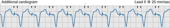
As in crosstalk, delivery of the safety output pulse causes a shortening of the base pacing interval because of the shortened A-V interval. If the baseline A-V interval is programmed to the same duration as that of the safety output pulse (this has become very common in biventricular devices when treating patients with congestive heart failure), or if a rate-modulated or differential A-V interval is present, the presence of safety pacing (i.e., crosstalk) may be difficult or impossible to discern on the standard ECG. The use of event marker telemetry documents the presence of crosstalk or safety output pulses in these situations (see Fig. 29-44).
Pacemaker-Mediated Tachycardia
Runaway Pacemaker
The runaway pacemaker is a pacemaker malfunction that may occur in single-chamber or dual-chamber pacing systems. It is usually the result of at least two separate component failures within the pulse generator. The result is the rapid delivery of pacing stimuli to the heart, with the potential for inducing lethal arrhythmias, such as ventricular tachycardia or fibrillation. All modern devices incorporate a runaway protect circuit that prevents stimulation above a preset rate, typically between 180 and 200 bpm. Although extremely rare with modern pacing devices, this represents a medical emergency (Fig. 29-45). Emergent surgical intervention to replace the device or, if all else fails, cut the lead, must be performed. Obviously, a patient who is pacemaker dependent presents a new challenge as soon as the defective pacing system is disabled.225,226
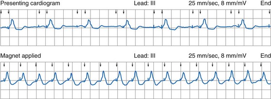
Sensor-Driven Tachycardia
Sensor-driven tachycardia is a rapid heart rate occurring in rate-modulated pacemakers. It can occur with any type of sensor-driven pacing system (Box 29-14). Interaction between the patient and external stimuli can cause the rate modulation system to overreact and pace at a high rate. The most common cause of this PMT type is inappropriate programming of the sensor parameters. In piezoelectric devices, a threshold setting that is too low or a slope setting that is too high results in high pacing rates for low levels of activity. It also exposes the patient to increased pacing rates for nonphysiologic events, such as riding in a car, exposure to loud noise or music, or sleeping on the ipsilateral side to the device implant.227–237
Box 29-14
Causes of Sensor-Driven Pacemaker Tachycardia
One unpublished incident concerned a patient with a bipolar piezoelectric VVIR device. The emergency medical squad had been summoned to treat an unconscious patient. They arrived to find the patient with seizure activity. On viewing the ECG, they found the patient’s condition to be wide-complex tachycardia at 150 bpm. The patient received repeated direct-current cardioversion for this tachycardia, without reversion to sinus rhythm. In this patient the seizures were caused by epilepsy, and the vibration-based sensor responded to the seizure by pacing at its upper rate. No spikes had been noted on the ECG because the output configuration was bipolar, which resulted in a diminutive artifact on the monitor (Fig. 29-46).
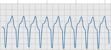
Devices that use thoracic impedance plethysmography to determine changes in minute ventilation may pace at the upper rate during marked hyperventilation, use of electrocautery, hyperventilation during anesthesia induction, and when close to an electrical power supply. Therefore, it is strongly recommended that this type of rate-modulating feature be disabled before the patient undergoes any surgical procedure (even if electrocautery is not used, because much electrical equipment is present in most operating room suites), treatment with a mechanical ventilator, or treatment in a critical care unit.236
Magnetic Resonance Imaging
Exposure to MRI scanners has been reported to cause inappropriately high pacing rates when tested in animals. Some pacemakers have been noted to pace at the radiofrequency (RF) pulse rate of the scanner. This situation resolves immediately with the cessation of the RF output by the scanner.238–243 MRI may also result in inhibition of the pacing output during the scanning process. Because of these issues, such scanning has been cautioned against by all manufacturers of pacemakers. This is true even though some patients have inadvertently or intentionally undergone MRI without problems. Some physicians have programmed devices in patients who are not pacemaker dependent to the OOO/ODO mode or to a subthreshold voltage output or pulse width, effectively disabling the pacemaker, and pacemaker-dependent patients have had the device programmed to an asynchronous mode. Although this may help, the induced current from having a wire in a moving magnetic field can theoretically stimulate the heart without being connected to the generator. One study reported that the induced current was subthreshold,244 even though the potential for stimulation existed. It has also been reported that the capture threshold may rise because of heating at the lead-myocardium interface.
Myopotential Tracking
Myopotential tracking is caused by oversensing of muscle potentials by the atrial channel in a dual-chamber pacing system capable of P-wave tracking. This has become much less common with the use of bipolar sensing, which is preferred by most implanting physicians. It is a greater problem with unipolar dual-chamber systems. A unique sensing modality—“combipolar” sensing, which is sensing between unipolar atrial and ventricular electrodes for a form of wide-dipole bipolar sensing with the entire system restricted to the heart—has the potential to reduce the incidence of atrial myopotential oversensing.245 Myopotential tracking occurs when the atrial channel senses the electrical activity of the muscle underlying the pulse generator. Those same signals, if sensed on the ventricular channel, would result in myopotential inhibition. The atrial sensitivity setting is usually more sensitive than in the ventricular channel, and myopotential sensing is more likely in the unipolar configuration. When myopotentials are sensed on the atrial channel, the atrial output is inhibited, and a ventricular output is triggered at the end of the AV interval. This pseudo–P wave repeatedly triggers the ventricular output, and ventricular pacing may occur up to the programmed maximum P-wave tracking rate (Fig. 29-47). If the myopotentials are of sufficient amplitude, they may be sensed on the ventricular channel, in which pacing system inhibition may also occur.88,89,120
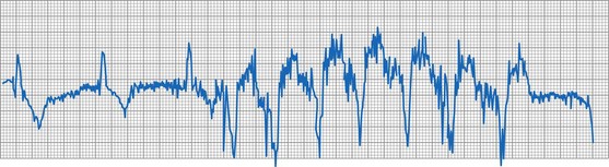
Endless-loop Tachycardia
The classic form of PMT is ELT, which can occur in dual-chamber pacemakers that are capable of atrial tracking modes, most often DDD or VDD. Only patients who are capable of retrograde ventriculoatrial (VA) conduction through the AV node or an AV accessory pathway are capable of sustaining this rhythm. The mechanism is identical to any macro-reentrant tachycardia in which two electrical pathways exist between the atria and ventricles. Pacemaker ELT is classically initiated by a PVC. The depolarization is conducted retrograde to the atria. If the PVARP has ended and the retrograde complex is of sufficient amplitude to be sensed, the atrial channel senses the event and initiates an A-V interval. At the end of the A-V interval, the pacemaker delivers a stimulus to the ventricle, and the loop is reinitiated (Fig. 29-48). Although PVC is the classic cause of PMT initiation, any situation that results in AV dissociation, allowing a ventricular depolarization to occur without a normally coupled atrial-paced or atrial-sensed event, may begin the loop (Box 29-15). Examples include atrial noncapture, oversensing, and undersensing. In addition, if the programmed AV interval is long (some units allow programming of an interval of up to 400 msec), it may be possible for the AV node to recover in time to conduct the subsequent ventricular-paced event in a retrograde direction, thus initiating another ELT (Fig. 29-49). The absence of anterograde AV nodal conduction does not rule out retrograde conduction over the AV node or a concealed AV accessory pathway. Patients may also exhibit intermittent retrograde conduction or have variations in the retrograde conduction time based on their sympathetic tone and catecholamine status.246–255
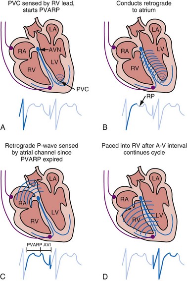
Figure 29-48 Classic initiation of endless-loop tachycardia by PVC in patient with retrograde AV conduction.
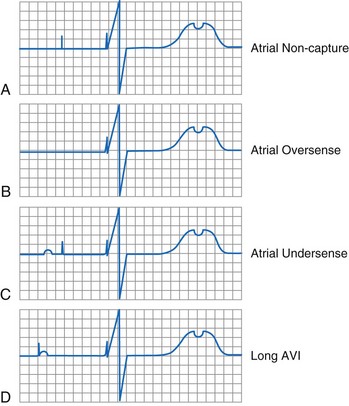
Figure 29-49 Initiating events leading to retrograde P-wave conduction and potential for endless-loop tachycardia.
The rate of ELT depends on the conduction velocity and refractory period of the retrograde AV pathway. If the retrograde AV conduction is the same as or shorter than the upper rate interval (but not shorter than the PVARP), the tachycardia rate is at the programmed upper rate. If the retrograde AV conduction time is slower than the upper rate interval, the tachycardia rate is below the upper programmed rate (Fig. 29-50). Therefore, although the rate of the ELT can never exceed the programmed upper rate of the pacemaker, it may be lower.254,256 When the rate is lower than the MTR, the rhythm has been termed a balanced ELT.
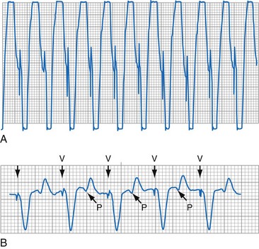
Prevention
The main defense against ELT is the use of an appropriate PVARP interval. During the PVARP, the atrial channel cannot respond to the retrograde depolarization that would initiate the ELT. This is independent of the source of that atrial event. If retrograde conduction is present during implantation or follow-up, it is a simple matter to measure the VA time and program the PVARP to an interval that is longer.250 Many patients, however, exhibit only intermittent VA conduction, making an accurate assessment difficult. The major limitation of using a long PVARP is that it limits the upper tracking rate of the device (2 : 1 blocking rate). Some patients in our clinics have VA times in excess of 430 msec. If a PVARP of 450 msec and an A-V interval of 150 msec are used, the total atrial refractory period (TARP) is 600 msec. This causes 2 : 1 blocking at an atrial rate of 100 bpm, which is much too low for most patients.
One solution to this problem is the use of ELT prevention algorithms.257,258 The most common algorithm is PVARP extension on PVE detection. A premature ventricular event is defined as a ventricular sensed event that is not preceded by an atrial paced or atrial sensed event. When a PVE is detected, the device prolongs PVARP by a fixed or programmable value for the next cycle. It allows a shorter baseline PVARP to be used, with associated higher 2 : 1 blocking rates. A variation on this technique is to initiate one DVI cycle after the PVE. This is the ultimate PVARP extension, because the atrial channel remains refractory to sensing throughout the entire AEI. A problem with most of the PVARP extension algorithms is that functional atrial noncapture may occur. Because there was an atrial output, the system returns to the shorter PVARP, thus allowing for retrograde conduction to be sensed after the AV paced cycle, simply postponing the ELT for one cycle. In the latter case, the pacemaker does not maintain the long PVARP because it has delivered an atrial stimulus (although ineffective) before a ventricular event. The subsequent ventricular paced event then leads to ELT (Fig. 29-51). A refinement to the standard PVARP extension algorithm is to extend the atrial alert interval at the end of the extended PVARP.246 On release of the atrial output at the end of the longer AEI, the atrial myocardium will have recovered, allowing for capture, thus precluding retrograde conduction on the next ventricular cycle.
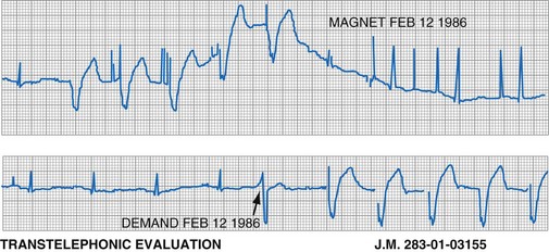
Figure 29-51 Dual-chamber pulse generator programmed with PVARP extension on premature ventricular event detection.
(From Levine PA, Selznick L: Prospective management of the patient with retrograde ventriculoatrial conduction: prevention and management of pacemaker mediated endless loop tachycardias, Sylmar, Calif, 1990, Pacesetter Systems.)
Newer approaches have been made possible by the advent of sensor-driven pacing systems. With a DDDR system, even though the MTR may be limited by a long PVARP, faster AV sequentially paced rates may be possible through the sensor. Even though atrial sensing does not occur during the PVARP, sensor-driven atrial pacing may occur. Another alternative in some DDDR pulse generators is to use an adaptive PVARP that is long when the sensor determines that the patient is at rest. When the patient’s sensor-indicated rate increases along with the need for higher heart rates, the PVARP is shortened proportionately, allowing higher rates before a 2 : 1 block upper rate behavior occurs. This approach allows the device to discriminate between early atrial depolarizations at rest (possibly retrograde beats or PACs) and sinus tachycardia with exertion.259–261 Even in the absence of rate modulation, rate-responsive AV delay algorithms allow a shorter TARP and therefore a higher MTR, even with a fixed, long PVARP.
A comparison of P-wave morphology can allow discrimination between sinus and retrograde atrial depolarizations in some cases; this is referred to as differential atrial sensing.262–266 Mapping of the atrium may allow positioning of the lead at a site that has a large P wave when generated by the sinus node and retrograde P waves that appear small in comparison. The pacemaker sensitivity may be programmed to allow sensing of the anterograde P wave but not the retrograde P wave. Therefore, ELT cannot be initiated or sustained because the loop cannot be completed. Although the retrograde P wave is usually of lower amplitude than the anterograde P wave, this is not always the case; the individual situation needs to be evaluated before any attempt to use atrial sensitivity as a discriminating factor. In addition, the atrial EGM may decrease in amplitude as the sinus rate increases under physiologic stress. Programming a reduced atrial sensitivity to facilitate discrimination between anterograde and retrograde P waves could compromise sensing of rapid intrinsic atrial rhythms.246
Another preventive mechanism has been to program a high MTR, in the hope of inducing retrograde fatigue and spontaneous termination of any ELT that is allowed to start. Careful assessment of the patient’s ability to conduct retrograde should be performed, however, because some patients have superior retrograde conduction (compared with anterograde conduction) and are able to sustain extremely rapid ELTs.246
Detection and Termination
The first criterion is sustained P-wave tracking at the upper rate. This is the most common method of ELT detection. If the pacemaker tracks the P waves at the upper rate for a specific number of intervals, then the PVARP is prolonged for one cycle, DVI is used for one cycle, or the ventricular output is withheld. The number of events at the upper rate that trigger an ELT termination attempt depends on the particular pulse generator. Some algorithms use a fixed number of beats; in other systems, this is a programmable option. The method of ELT termination may also be programmable (PVARP extension, DVI cycle, or atrial pace).267,268
The third approach to identifying ELT is modulation of the A-V interval during sustained P-wave tracking at or above a specific rate. The technique is based on the observation that the VA conduction time in an individual patient is relatively constant. When the device is P-wave tracking at a high rate, the system first assesses the stability of the retrograde interval. The A-V interval is then either shortened or lengthened, and the effect on the subsequent retrograde interval is assessed. If an ELT is present and the V-pace to P-sense interval remains constant (i.e., atrial cycle length is shortened by shortening of A-V interval), the device confirms ELT and initiates a termination algorithm (Fig. 29-52), either by withholding the ventricular output or by delivering an atrial output after a period sufficient to allow for atrial recovery.260,261 However, if the V-pace to A-sense interval changes by more than a preset amount (i.e., atrial cycle length is unaffected by A-V interval shortening), ELT is not confirmed, and the device continues to track the atrium normally.
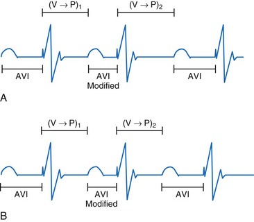
Cross-Stimulation
Cross-stimulation can be defined as stimulation of one cardiac chamber when stimulation of the other is expected (Fig. 29-53). An embarrassing cause of this phenomenon is inadvertent placement of the ventricular lead into the atrial connector and the atrial lead into the ventricular connector of the pulse generator. Dislodgment of either lead into the other chamber may also be a cause. Coronary sinus placement of either lead, either intentionally or accidentally, can cause continued or intermittent cross-stimulation. For all of these situations, surgical revision of the pacing system is the only option for correction. There have been several reports of cross-stimulation not related to these situations.269–272 Internal crossover within the pulse generator circuitry may be the cause. This can be seen in dual-chamber unipolar systems with the leads connected but before placement in the pocket, as the current crosses from one electrode to the other and then back to the pulse generator through the other lead. In this case, because the atrial output is first, atrial capture is obscured by ventricular capture. Because the impedance in this system is high, it requires a high output with a very low capture threshold. After the pulse generator is implanted, this phenomenon ceases. (There is also a system that has internal energy crossover when a magnet is applied to the pacemaker. Here, too, the amount of energy crossover is minimal, and capture can be demonstrated only when the capture threshold is very low. In all cases, crossover resolved after several weeks, as lead maturation resulted in a rise in the capture threshold.)
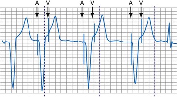
Repetitive Non-Reentrant Ventriculoatrial Synchronous Rhythm
The repetitive non-reentrant VA synchronous rhythm is becoming increasingly common with the growth of the DDDR and DDIR modes. It represents a classic example of an adverse interaction between a normally functioning dual-chamber pacemaker and a patient. A prerequisite for this rhythm is intact retrograde conduction. Further, the pacemaker must be programmed with a PVARP that is sufficiently long so that retrograde conduction does not induce ELT. The second prerequisite is a sufficiently high base rate such that there is a relatively short atrial escape interval and an even shorter interval from the retrograde atrial depolarization that renders the atrial tissue physiologically refractory. The retrograde P wave is not sensed because it coincides with the PVARP. This represents functional undersensing. Because of the relatively high rate and the failure to reset the atrial timing cycle (because the retrograde P wave is not sensed), an atrial output is delivered when the atrial myocardium is physiologically refractory. This results in functional atrial noncapture. Thus, after the ineffective atrial output, the A-V interval times out, and a ventricular paced event occurs, by which time the AV node and atrial myocardium have fully recovered, allowing retrograde conduction. The result is an AV paced rhythm with repeated functional atrial noncapture and functional atrial undersensing, all caused by a coincidence of various key timing intervals. This rhythm is called either repetitive non-reentrant VA synchrony or AV desynchronization arrhythmia.273–275 The effect on the patient is the same as that of ventricular pacing with retrograde conduction but in a DDDR/DDIR pacing system. This can lead to symptoms of palpitations, dyspnea, and even syncope. Effectively, the resultant rhythm is a classic rhythm associated with pacemaker syndrome, but unless one recognizes the problem, either normal pacemaker function is diagnosed and the symptoms are unexplained, or the disorder is labeled atrial noncapture and inappropriate efforts are directed toward correcting this “malfunction.”
It is absolutely essential that the clinician fully understand the interaction between the timing circuits in the pacemaker and those in the heart. The author knows of a patient who was taken back to the operating room for an atrial lead repositioning on two additional occasions after the initial implantation because of this rhythm and the implanting physician’s failure to understand the adverse interaction between the various programmed parameters and the patient’s intrinsic rhythms. This was not a lead dislodgment or malposition, although the latter was the working diagnosis. The problem could not be solved by repositioning of the lead, yet that was the diagnosis by the referring physicians because of repeated failure to capture on the atrial channel at the highest outputs that the pacemaker would allow. When evaluated by a knowledgeable physician, this rhythm was suspected because the referring physician described losing atrial capture at 0.5 V and then not being able to regain it at 7.5 V when the base rate was 90 pulses per minute (ppm), but having absolutely no problems with capture when the base rate was 60 ppm. The referring physician sought advice about where the lead could be positioned (on a fourth operative procedure) to prevent repeated loss of atrial capture. Rather than reoperate, it was advised to leave the rate low and disable the rate modulation. The patient was then sent for a detailed evaluation, at which time it was easy to induce and demonstrate this phenomenon with the aid of the telemetered atrial EGM and event markers (Fig. 29-54). Management was more of a challenge, in that the maximum sensor rate had to be limited to preclude atrial pacing at a high rate, which meant that there would be a relatively short atrial escape interval. This patient’s adverse rhythm was triggered by early atrial premature beats.
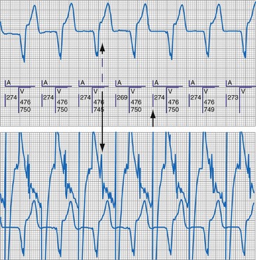
Follow-Up Recommendations
Follow-up of pacing systems has evolved with their increased complexity. The newest devices are able to report automatically determined capture and sensing thresholds. Although these are quite accurate, they are not always reliable. Some capture management algorithms can be foiled by high polarization leads, or frequent fusion beats caused by AF, or programmed A-V intervals that allow fusion and pseudofusion. Review of the graph showing the capture thresholds over time will show intermittent high thresholds or many aborted searches (see Fig. 29-24). If this is seen, reprogramming of the AV interval to avoid fusion or turning off the algorithm may be necessary to avoid sustained high-output pacing.
 Conclusion
[/level-membership-for-cardiovascular-category][not-level-membership-for-cardiovascular-category]
29 Pacemaker Troubleshooting and Follow-up
Bidirectional Telemetry
Telemetry is the ability to transmit information or data from one device to another, a capability that was essential to the introduction of pacemaker programmability. This is the ability to noninvasively change the functional and diagnostic parameters of the pacing system by coded commands transmitted to the pacemaker from a programmer.1–4 The first generation of programmable pacemakers used unidirectional telemetry from the programmer to the pacemaker but was not able to transmit data from the pacemaker to the programmer. This limited the confirmation of a programming change that was electrocardiographically silent (e.g., sensitivity, refractory period) when a parameter was programmed.
Bidirectional telemetry is communication in two directions. With respect to pacing systems, this means that the pacemaker and programmer can communicate with each other, an essential capability for the development of the multiple diagnostic capabilities that are the subject of this chapter.5,6 First implemented in rechargeable pacemakers, bidirectional telemetry was developed to confirm the proper alignment of the recharging head with the implanted pacemaker. When the recharging wand was not aligned properly with the pacemaker, there was an audible beep from the charging unit to notify the patient and whoever was in attendance of this condition. When the two devices were properly aligned, the system was silent.
Bidirectional capability was next applied to confirmation of programming. This was particularly valuable for those parameters that did not result in an overt change in pacing system performance and could not be independently identified on an electrocardiographic recording. This ability is essential for the DDDR pacemaker and modern implantable cardioverter-defibrillators (ICDs), because these devices can have dozens of independently programmable parameters, most of which are not readily identifiable on the electrocardiogram (Fig. 29-1, A). Bidirectional telemetry allows interrogation of programmed parameters and measured data when the patient is seen during follow-up for routine evaluation, during remote follow-up interrogation, or for a suspected pacing system malfunction. Without this feature, there would be no way to determine the current settings of a device for features other than rate and pulse width. It also makes the retrieval of detailed data collected by the pacemaker in its various event counters feasible. Presently, interrogation of pacemaker settings and data can be accomplished remotely. This technique uses a device located in the patient’s home, a physician’s office, or anywhere an Internet connection or telephone service (wired or cellular) connection is available. Data are retrieved from the device and sent to a central receiving station. The data are made into a report and then can be faxed to the appropriate individual or made available through an Internet website portal. Although the technology exists to allow programming remotely, this is not currently available because of regulatory issues.
Measured Data
Complementing the interrogation of programmed data is the provision of measured data, including data obtained from the pacemaker detailing information on lead and battery function at evaluation. Information regarding demand and asynchronous rates may also be measured (Fig. 29-1, B). Telemetry allows this information to be transferred from the pacemaker to the programmer for evaluation by the clinician.
Battery Status
Although not all systems provide the information in the same manner (some are graphic and others are numeric), data concerning battery function often include a measure of battery voltage, impedance, and current drain.7–11 All three parameters are interrelated. The battery current drain is a measure of the average current being drawn from the battery, assuming 100% pacing at the programmed rate and output settings. Inhibition or pacing at higher rates, as might occur with intrinsic rhythm or sensor drive, respectively, directly affects the functional battery current drain, as do changes in lead or stimulation impedance. The reported current drain is only an estimate of the actual battery current drain. Newer devices are able to estimate remaining longevity based on true current drain measurements, giving a much more accurate assessment (see Fig. 29-1, C).
Given the degree of programmability of most current pacemakers, a dual-chamber pacemaker programmed to pace all the time at maximal output on each channel may last only 2 years. An identical model programmed to outputs of 2.5 V or lower on each channel that are inhibited a significant portion of the time may be anticipated to function properly for 10 years or longer. It would be inappropriate to follow the second unit on a monthly basis beginning 1 year after implantation, whereas it would be equally inappropriate to plan only annual checks on a pacing system programmed with high outputs and 100% pacing. By following some measure of the status of the battery, either directly or indirectly, the clinician can achieve a qualitative assessment about when to increase the frequency of pacing system follow-up.12
There are two primary indicators of battery status: battery voltage and battery impedance. Battery voltage progressively decreases over time. The lithium/iodine (Li/I2) power cell is the most common power source in pacemakers, whereas the power source in an ICD is lithium/silver vanadium oxide (Li/VSO). Some of the newer pacemakers are now using Li/VSO–polycarbon monofluoride (LVSO/P). The nominal unloaded output voltage of the Li/I2 cell is 2.8 V, with each manufacturer triggering the RRT indicator at a specified battery voltage based on circuit design considerations. LSVO/P in pacemaker application has an initial voltage of 3.20, with an early drop to 2.90 V, where it plateaus, then drops to an elective replacement voltage of 2.60 V. The battery voltage and programmed output voltage are not identical. The “programmed output voltage” is achieved by modifying the 2.8-V battery output with either voltage multipliers or charge pumps to provide a higher voltage. The battery voltage can also be divided to deliver a voltage lower than 2.8 V. As energy is consumed, the battery voltage progressively decreases because of increased internal impedance. Even with decreasing battery voltage, the device circuitry is designed to maintain the stability of the programmed voltage delivered to the patient. The ability to track the progressive decrease in battery voltage and increase in battery impedance provides an effective guide to the clinician regarding the frequency with which the pacing system should be routinely checked for signs of battery depletion (Fig. 29-2). In addition, the measured battery voltage is affected by the battery current drain: the higher the current drain, the lower the battery voltage.
Battery voltage and impedance may be tracked together or individually. If these measurements are provided to the manufacturer’s technical service engineers, along with the programmed parameters and an estimate of the percentage of pacing versus inhibition, the remaining longevity of that pacing system can be estimated with reasonable accuracy, assuming that the various parameters remain stable. These calculations have more recently been incorporated into the programmer interface to provide an online estimate of longevity in years or months. These estimates are sometimes shown as a range based on the tolerances of the battery measurements (i.e., giving minimum and maximum ranges of longevity), as well as an estimate based on present current drain and actual device use based on data acquired from the event counter diagnostics (see Fig. 29-1, B).
Lead Status
The clinician can use knowledge of lead impedance to monitor and identify a developing mechanical problem with the lead. This requires baseline and historical data to recognize subtle changes that may reflect conductor fracture or an insulation breach. It is essential to know what device is being used to make these measurements. As noted previously, different devices may obtain these data at different points of the pacing stimulus. Because of these differences, the impedance measurement obtained with a pacing system analyzer at implantation may be significantly different from that obtained by telemetry from the implanted pacemaker moments, if not years, later. This difference does not necessarily imply a problem. Furthermore, impedance may naturally evolve over time, with a fall in impedance occurring during the days to weeks after implantation, followed by a gradual rise toward the initial measurements. Multiple factors may affect impedance, particularly in a unipolar system. For example, measurements obtained during deep inspiration may significantly differ from those obtained during maximal exhalation. In the same patient, impedance measurements based on a single-output pulse have been reported to vary by 100 ohms (Ω), or even more, during the same follow-up evaluation, while remaining consistent with normal function. If a marked change in lead impedance from previous measurements (e.g., >200 Ω) is encountered during a routine follow-up evaluation, the pacing system should be further evaluated.13,14 If the patient has no clinical symptoms and has stable capture and sensing thresholds, surgical intervention would be premature, although more frequent follow-up in the office or by remote interrogation would be prudent. However, a dramatic change in telemetered lead impedance in the presence of a clinical problem directs the physician toward the likely source of the difficulty (Fig. 29-3).
A dramatic fall in impedance usually reflects a break in the insulation.15–17 In a unipolar system, an insulation problem provides an alternative pathway for current flow starting closer to the pulse generator, resulting in less energy reaching the heart. An outer insulation break in a bipolar lead tends to result in “unipolarization” of the lead. The amplitude of the stimulus artifact as recorded by an analog electrocardiogram (ECG) is determined by the distance the current travels in the tissues from the cathode (tip electrode) to the anode (ring electrode or housing of the pulse generator). A normally functioning bipolar pacing system in which both active electrodes are inside the heart, separated only 1 to 2 cm, results in a small stimulus artifact. In a unipolar system, the current travels from the tip electrode to the housing of the pulse generator, and therefore the stimulus artifact is large despite equivalent output settings. Some of the newer digital ECG designs result in a marked signal-to-signal variation in amplitude as a result of the digital sampling rate of the recording system. Other recording systems create an artificial uniform amplitude artifact with any high-frequency electrical transient, thereby precluding differentiation of a bipolar from a unipolar pacing system based on the analysis of the ECG recording.
In a previously stable system, a mechanical problem developing with the lead—either a breach in the insulation or a conductor fracture—results in a change in the stimulation impedance, which may be reflected by a change in the ECG-recorded stimulus artifact (Fig. 29-4). In a bipolar pacing system, an insulation defect between the proximal conductor and the tissues of the body is not likely to affect capture thresholds, but it results in a larger stimulus artifact, making it appear unipolar. Depending on the actual location of the insulation failure in either the bipolar or the unipolar lead, stimulation of the extracardiac muscle contiguous to the insulation defect may occur. Insulation failures may also attenuate the electrical signal reaching the pacemaker, possibly resulting in sensing failure.
Programming of the output configuration to unipolar (most pacing systems, but not ICDs, now have this capability) may prevent the loss of capture and possibly undersensing from an internal short circuit. This does not prevent the oversensing behavior associated with make-break electrical transients generated by intermittent contact between the two conductors, as is caused by failed inner insulation. Typically, a bipolar lead with failed internal insulation exhibits a higher impedance when pacing is programmed to the unipolar rather than the bipolar output configuration.18,19 This is opposite to the expected higher impedance of a bipolar system. Although programming to a unipolar configuration may result in an apparent resolution of a malfunction, it is not a cure and should be considered only as a temporary measure, one that allows the observed problem to be managed on an elective rather than emergent basis. The malfunctioning lead should be replaced expeditiously.
An increase in lead impedance may be the result of a conductor fracture or a connector problem.20 When this occurs, the lead impedance often rises to high levels. It is inappropriate, however, to assume that a normal lead impedance is 500 Ω. Leads are available that are designed to have high impedance, with values ranging from 1500 to 2500 Ω. Other leads, at implantation, may have an impedance in the range of 250 to 300 Ω. Therefore, it is essential to look for a trend in serial lead impedance measurements rather than a single measurement. Impedance, taken in conjunction with the stability or changes in capture and sensing thresholds, is the best way to determine the condition of a pacing lead. A mechanical problem with the lead—either a conductor fracture resulting in high impedance or an insulation failure resulting in low impedance—eventually results in an overt clinical problem that can be identified by telemetric measurement of the stimulation impedance. If the impedance is sufficiently high, there is no current flow and no effective output. It must be understood that, although the telemetered event markers indicate a pace output, there may be loss of capture. The reduced current flow also results in a fall in the measured current drain of the battery. Note that any problem may be intermittent. This typically occurs when the two broken ends make contact at times but are separated at other times, or in the case of an insulation failure, when lead movement either opens the compromised area or pushes the edges of the break together, resulting in intermittent normal function.
Some pacemakers are able to report lead impedance measurements on a beat-by-beat basis, allowing the clinician to observe the digital readout of lead impedance on the programmer screen over many cycles. As with the oscilloscopic monitoring of the pulse wave morphology, this technique reduces but does not eliminate the incidence of false-negative results. A further enhancement is the “automatic periodic monitoring” of lead impedance, which results in a graphic display reporting the history of lead impedance performance. Measurements can be obtained continuously or daily. This increases the frequency of measurement, increasing the likelihood of diagnosing an intermittent lead problem and possibly intervening on an automatic basis (Fig. 29-5). Some devices respond by automatically programming the pacemaker from bipolar polarity to unipolar in the presence of either a marked rise in impedance, reflecting a conductor fracture,21 or a marked drop in impedance, consistent with an insulation failure.
Event Marker Telemetry
To facilitate interpretation of the paced rhythm, almost all modern pacing and ICD systems incorporate the ability to transmit information regarding real-time pacing system behavior to the programmer. These data are displayed on the programmer screen and may also be printed as well. Both paced and sensed events are communicated to the programmer. Displayed as a series of positive or negative marks, with or without alphanumeric annotation, these are generically termed event markers. They have the greatest diagnostic value when superimposed above or below a simultaneously recorded surface ECG (Fig. 29-6). Some systems also display the duration of the atrial and ventricular refractory periods and interval measurements. Others show events that are sensed during the refractory period even though they do not play a role in altering the system timing (i.e., they are sensed but not used). Events may be displayed either in real time or after the tracing has been frozen on the programmer screen using cursors to identify the interval of interest. If the real-time monitor screen method is used to show the rhythm and event markers, the tracing may be frozen and then printed for inclusion in the medical record.
Figure 29-6 Surface ECG and simultaneous event markers.
Data are from a Pacesetter Trilogy DR+ Model 2360 (St. Jude Medical CRMD, Sylmar, Calif).
Event markers (also called marker channels, annotated event markers, and main timing events by various manufacturers) are most effectively used when they are displayed with a simultaneously recorded ECG rhythm.22–25 Without the ECG, the event marker simply reports the behavior of the pacemaker. This information is valuable in showing that an output has been released or that sensing has occurred. It does not confirm that the stimulus effectively resulted in capture, or that a sensed event was a true atrial or ventricular depolarization. The presence of an output marker does not confirm that the stimulus even reached the heart. The output marker serves only to confirm that the pacemaker delivered a stimulus from its output circuit. This notation is transmitted directly from the pacemaker to the programmer by way of the telemetry module. An open circuit (e.g., a fractured conductor coil) may preclude the output pulse from reaching the heart, but the pacemaker would indicate that an output pulse was released. Similarly, a native depolarization may not be sensed, allowing the pacing stimulus to be released at a time when the myocardium is physiologically refractory. If the markers reported that an event was sensed on the atrial channel and was followed by a ventricular output pulse after a preset delay (known as P-wave synchronous ventricular pacing or tracking), the clinician would know that the pacemaker was capable of sensing in the atria and pacing in the ventricles. Without a simultaneously recorded ECG, it would be impossible to determine whether the pacemaker was responding to inappropriate signals on the atrial channel, whether the ventricular stimulus was effective, or whether a native QRS complex was present but not sensed. Therefore, telemetered event markers are most effective when displayed with a simultaneously recorded ECG.
Event Marker Displays
The next improvement was to transmit coded signals representing paced and sensed events from the pacemaker to the programmer. The programmer reconstituted these signals into a series of varying-amplitude pulses or alphanumeric labels representing paced or sensed events. These could be either displayed on a monitor screen or recorded using a printer integral to the programming system, which allowed for the simultaneous recording of a surface ECG acquired by way of a separate set of cables. The simultaneous ECG and markers allowed the clinician to correlate the behavior of the pacemaker directly with the patient’s rhythm, to determine whether the system is functioning properly. A calibration signal composed of a series of different amplitude pulses or a legend of the cryptic labels allowed the clinician to interpret the various markers (Fig. 29-7). In an early series of markers, the largest pulse represented a pacing output, the intermediate one indicated a sensed event, and the smallest represented either the end of the refractory period or a sensed complex that occurred during the refractory period. With the advent of dual-chamber pacing systems, a marker pulse extending above the baseline identified atrial events, and ventricular events were labeled with a pulse extending below the baseline. This type of marker system has become obsolete, and there are very few devices remaining as active implants that use this scheme.
One method for single-chamber pacing systems with event marker telemetry uses the letter P to reflect a paced event and S to represent a sensed event. This may cause confusion with other dual-chamber systems in which the letter P reflects a sensed atrial event indicative of a native P wave (with which most medical personnel are familiar, based on their knowledge of the standard ECG). The interpretation of the alphanumeric event markers is often product specific, and the clinic personnel who evaluate the pacing system must take this into account (Fig. 29-8).
Other symbols may be used for a paced or sensed event and are usually displayed with an identifying key on the resultant printout. Each paced or sensed event may also be identified by a vertical line, going up in the case of atrial events and down for ventricular events. In some cases, a difference in the amplitude of these lines has been retained in conjunction with the alphanumeric lettering. Indeed, as the complexity of the devices increases, the variety of symbols and letters identifying specific events and behaviors is also increasing (see Fig. 29-8).
Laddergramming
Laddergramming is an advanced adjunct to the interpretation of clinical arrhythmias. It was incorporated in some programming systems by using the known programmed parameters of the pacemaker combined with the event marker information telemetry from the implanted pacemaker23–26 (Fig. 29-9). For all the elegance of these graphic interpretations of the pacemaker’s behavior, they still require the simultaneously recorded ECG rhythms. Although the pacemaker may be functioning normally, in that it is behaving properly with respect to its programmed parameters, failure to capture or properly sense would not be diagnosed from the various diagrams and markers without the simultaneously recorded surface ECG.27 Laddergramming has become a teaching tool at this time, because no programmers currently provide this level of graphic description.
Event Marker Limitations
Several limitations are associated with event marker telemetry. First, used alone, markers report the behavior of the pacemaker but do not allow the clinician to determine whether this behavior is appropriate for the patient.27 In this regard, markers are analogous to the hand-held digital counters that report pacing rates and intervals. The counters only detect and report the pacing stimuli, not whether these output pulses are effective in causing a cardiac depolarization, or whether native events are properly and consistently sensed. A long interval between consecutive pacing stimuli could reflect normal function because the pacemaker responded appropriately to a native complex, or it could represent a system malfunction with oversensing or no output (e.g., from intermittent lead fracture). Neither event marker telemetry nor the digital counters should be used independently of a simultaneously monitored ECG rhythm.
Most pacemaker event marker telemetry is limited to real-time recordings. The markers must be telemetered from the pacemaker to the programmer or another display system while the rhythm is being actively monitored. Neither the pacemaker nor the programmer can retrospectively provide markers for a previously recorded rhythm. If the pacemaker is responding to events that are not visible on the surface ECG, the event marker simply confirms this fact but does not identify the specific signal. An evaluation of sensed but otherwise invisible events requires intracardiac electrogram telemetry or an invasive procedure to record the signal from the implanted lead. Many premium-level pacemakers can store event markers with or without electrograms. Markers may be stored using a patient trigger (e.g., magnet application),28 a simple battery-operated radiofrequency transmitter, or on spontaneous activation of predefined algorithms or sequences of sensed or paced events.
Electrogram Telemetry
At implantation, the amplitude of the EGM is usually measured with a pacing system analyzer (PSA) that reports a millivoltage amplitude. The PSA uses its own unique set of filters, which frequently is not identical to those in the pacemaker’s sense amplifier. Therefore, the reported PSA signal, at best, provides an approximation of what the pacemaker effectively sees. Newer pacing system analyzers are now being introduced that will allow adjustment of the filters to match specific models of pacemakers and ICDs to eliminate this discrepancy. Likewise, the morphology of the EGM observed on a high-fidelity monitor is not identical to the signal as seen by the pacemaker, because filters in the pacemaker’s sense amplifier usually have a narrower band-pass and therefore block out some of the frequencies (Fig. 29-10). Examining the EGM recorded with a physiologic recorder or telemetry with a wide band-pass can provide valuable information on the slew rate, splintering of the intrinsic deflection, and other morphologic abnormalities.
Figure 29-10 Side-by-side display of telemetered bipolar ventricular electrograms.
These signals were telemetered from a Pacesetter Affinity DR pacemaker, Model 5330 (St. Jude Medical CRMD, Sylmar, Calif).
Measurements of the peak-to-peak amplitude of the EGM, as recorded at implantation or as telemetered from an already-implanted pacemaker, are typically used to determine the sensing threshold. This approach may be inappropriate if the frequency content of the signal is outside the constraints of the band-pass filter of the sense amplifier. If the clinician wants to determine the sensing threshold for a given patient, the sensitivity of the system should be progressively reduced until the system no longer consistently senses the native signal. The least sensitive setting (usually identified by millivolt amplitude) at which there is consistent sensing is the sensing threshold. The precision of this measurement is limited by the number and range of programmable sensitivity options in the specific model of pacemaker.29–31 All modern pacing systems now have the ability automatically to measure the EGM amplitude and report this to the clinician. This measurement is done through the pacemaker’s band-pass filter and therefore is a good estimation of the EGM size. The limitation to this method occurs when there is a large beat-to-beat or respiratory variation of the EGM size. The best method available uses this automatic measurement together with a beat-by-beat digital readout of the EGM amplitude. With this approach, the range of actual EGMs can be accurately evaluated. Unfortunately, this method of measurement is not widely available.
Other EGMs are obtained after the signal is processed by the pacemaker’s sense amplifier. As shown in Figure 29-10, both filtered and unfiltered EGMs may be available. Although the unfiltered telemetered EGM should not be used to determine the sensing threshold, it has many other roles.32,33 A primary value is in identifying signals that are being sensed but are not visible on the surface ECG. Another role is to facilitate analysis of the timing of the pacing system, because the sensed intrinsic deflection resets one or more timers. The intrinsic deflection at which sensing occurs can best be identified from the EGM; it is only indirectly measured from the surface ECG. In many cases, the telemetered EGM may be used to confirm capture (particularly atrial) when the evoked complex (P-wave or QRS) is not visible in any lead of the surface ECG.34,35 The evoked EGM may be enhanced by using a unique output pulse configuration to help cancel the residual polarization artifact, or by recording the signal through electrodes not directly involved with the output pulse. The output pulse tends to overload the telemetry or sense amplifier, driving the signal off scale. This is followed by a refractory period within the telemetry amplifier before anything can again be recognized. However, many of the newer pacing systems have more advanced telemetry systems that are able to blank the output pulse and quickly recover to provide high-quality EGM signals.
The telemetered EGM has been effectively used to diagnose native arrhythmias, in which the pacemaker is simply an innocent bystander, or to identify retrograde P waves not visible on the surface ECG. The latter ability may facilitate programming of the PVARP to prevent pacemaker-mediated tachycardia.35–43 The telemetered EGM provides clues to why episodes of undersensing may be occurring, including splintering of the EGM and low slew rates, which may place the signal outside the tight constraints of the pacemaker’s sense amplifier, despite an adequate peak-to-peak amplitude44 (Fig. 29-11).
The telemetered EGM can also be monitored periodically to follow the progression of the patient’s intrinsic disease process. A decrease in the amplitude of the telemetered EGM was reported to identify early rejection effectively in cardiac transplantation recipients; a return to the baseline amplitude correlated with resolution of the rejection process.45 Preliminary work on the signal-averaged EGM, either atrial or ventricular, suggests that it may be helpful in identifying disease in the respective chamber that is beyond the resolution of signal-averaging the surface ECG.46
Limitations of Electrogram Telemetry
The apparently adequate amplitude of the telemetered EGM for sensing does not mean that the pacemaker will sense it. The telemetry amplifier may use filters different from those in the sensing circuit, providing qualitative rather than quantitative data on the EGM (see Fig. 29-11). In most pacing systems, telemetered EGMs also have limitations similar to those of event markers. EGMs are real-time recordings and cannot be retrospectively provided by the programmer to facilitate the interpretation of an earlier ECG.
Real-time telemetry allows the physician to analyze the behavior of the pacing system when the patient is in the physician’s office or clinic while these diagnostics are being accessed with the programmer. This is impractical over a long period. In addition, it does not allow the patient to move around much while these recordings are being obtained. Long-term monitoring of pacing system behavior requires a Holter monitor, a loop memory recorder, or event counter telemetry, depending on the desired degree of precision. Pacemakers with microprocessors and significant random access memory (RAM) can now store select EGMs,47,48 as well as event markers, when triggered by the patient or by a predefined set of circumstances. This may greatly reduce the need for Holter or other monitoring techniques to evaluate intermittent symptoms in patients with pacemakers.
Event Counter Telemetry
The first use of stored diagnostic data in cardiac pacemakers was associated with the introduction of multiparameter programmability. Simple data using codes to identify implant indications and medications could be downloaded into the pacemaker for retrieval at subsequent follow-up evaluations. This ability has been expanded, allowing entry of free text (date of implantation, lead model numbers, pharmacologic regimens, and acute implant measurements, including capture and sensing thresholds and lead impedances; see Fig. 29-1, B). This information is printed with the programmed parameters each time the pacemaker is interrogated.
Total System Performance Counters
The simplest systems keep track of the number of times a pacing stimulus is released or a native complex is sensed. This allows for an assessment of the degree to which the pacemaker was used by calculating the percent pacing in each chamber. A refinement of this ability allows the pacemaker to diagnose bradycardia and, in the dual-chamber modes, to determine whether the bradycardia was the result of sinus node dysfunction or AV block. Event counters with this ability have also been termed diagnostic data, implanted Holter systems, and data logging.49–55
This information may be collected in conjunction with events occurring in specific rate bins, allowing for a detailed report of heart rate distributions. Additional data collected include the percentage of pacing in the atrium and ventricle, length of time at the maximum tracking rate, and the number of episodes in which the pacing system reached the programmed upper rate limit (Fig. 29-12). Additional data may be recorded regarding mode-switching events, pacemaker-mediated tachycardia (PMT) termination algorithm use, or the number of times any one of several other special features was activated. The counters are able to continue to accumulate data until one of the pacing state bins is full and cannot accept additional information. At this point, one or more of the counters are frozen. The volume of data that can be stored depends on the memory capacity of the pacemaker that is dedicated to these features.
Storing a simple marker of the pacing state and rate requires relatively little memory compared with storing waveform data representing the rhythm, as depicted by a consecutive series of EGMs. A theoretical 100-Hz bandwidth with 200 samples per cardiac cycle at eight bits of resolution per sample, recording the entire rhythm during a 24-hour period, would require 140,000,000 bits/day, even if the heart rate was a steady 60 beats per minute (bpm).47 Most implantable defibrillator systems store a series of EGMs preceding and following the delivery of antitachycardia therapy. Premium pacing systems use certain triggers to initiate EGM storage. These triggers may be a high atrial or a high ventricular rate, initiation of mode switching, or activation of any of several other specialized algorithms. Storage may also be triggered by application of the magnet or use of a simple transmitter device by the patient when symptoms are present. An early method to save memory was to provide “snapshots” of representative complexes; the trigger to store these data in an ICD was delivery of antitachycardia therapy. Extensive storage of cardiac rhythm data within pacemakers became possible with increasingly sophisticated data compression algorithms and more memory than previously available. Higher-bandwidth data transmission channels are required for this volume of data storage, particularly for long series of rhythms, so that transmission can be accomplished as efficiently and as quickly as possible.
When the additional ability to monitor a series of rates and pacing states is added, chronotropic function can be assessed by the distribution of atrial sensed rates (AS-VS or PR and AS-VP or PV; see Fig. 29-12). Furthermore, atrial pacing at rates above the programmed base rate reflects sensor drive in the DDDR pacing systems, providing an overview of the sensor behavior. The ability to report both rates and pacing states can provide the clinician with a better insight into the cause of PVEs as well as overall pacing system function. True premature ventricular contractions tend to occur at short coupling intervals, which is equivalent to a rapid rate. Large numbers of PVEs might suggest recurrent ventricular arrhythmias.56,57 If there are large numbers of PVE counts at relatively low rates, the clinician should consider episodes of atrial undersensing or accelerated junctional rhythms, which would also fulfill the pacemaker’s criteria for a PVE (i.e., a sensed R wave not preceded by an atrial event).
Subsystem Performance Counters
An increasing number of specific algorithms and capabilities are used either intermittently or potentially independently of the functional performance of the pacing system. An early counter representative of this capability is the sensor-indicated rate histogram, which reports the distribution of pacing rates that would have occurred had the sensor been totally controlling the pacing rates.58,59 This counter reports the sensor-defined rates, even if the pacemaker was inhibited by a faster native rhythm or the actual functional rate was being controlled by the sensed atrial activity (Fig. 29-13).
Other subsystem performance counters include automatic mode switch histograms, reports of the cumulative length of time for which the system functioned at MTR, number of times the PMT algorithm was enabled, high atrial or ventricular rate episodes (Fig. 29-14), and sudden rate-drop episodes. These diagnostic counters provide detailed information about the use of a specific algorithm or system behavior that is not activated daily or is not visible on the ECG, making identification difficult using standard recording techniques such as a Holter monitor.
The principal limitation associated with the two types of counters so far described is that counts are placed in a bin, either the pacing state alone or the pacing state and rate, which provides a one-dimensional view of the system’s behavior. If the period of monitoring is short, as during a casual or brisk walk, the clinician can reasonably assess the behavior of the pacing system. Longer periods of monitoring accumulate and overlap the results of many activities. This precludes an assessment of the pacing system’s behavior during a specific activity, or the identification of a symptomatic episode occurring at an earlier time. The ability of the system to store pacing state and rate data with respect to time (i.e., time-based event counters) has been variably termed event record or pacemaker Holter systems.60–62 Technically, this is not yet a true Holter monitor, because continuous rhythm recordings are not retained in memory, even though rate data may be available.
Time-Based System Performance Counters
The other option is to collect the data continuously. As the counters fill, new data are added at the expense of the oldest data (Fig. 29-15). This has been called rolling trend, final trend, or continuous data storage and is based on the “first in, first out” (FIFO) principle. When the patient is seen in follow-up, the data acquired over the time immediately preceding the interrogation of the system are available for review. The patient can often recall symptoms and activities during this period. These can be correlated with the behavior of the pacing system at the time of the symptoms. In this manner, the clinical staff caring for the patient may further assess chronotropic function, the behavior of the pacemaker during a variety of special or usual activities, and whether the sensor and other algorithms are behaving appropriately. The clinician may gain insight into the cause of palpitations and other symptoms that may have occurred during this time by correlation of the recorded data and the patient’s complaints or activities.51,58–62
Figure 29-15 Event record display.
Display is from a Pacesetter Trilogy DR+ Model 2364 (St. Jude Medical).
Sensor-input data have been combined with the actual rates achieved to facilitate reprogramming of the sensor parameters. Once acquired, the data from an exercise session are retained in the memory of the programmer, uploaded to the programmer, and then displayed on a screen. The system’s performance is based on a given set of sensor parameters that were in effect at that time. Because the pacemaker has the actual sensor-signal data, it can calculate how the unit would perform in response to a different set of sensor parameters. If a new set of sensor parameters is entered into the programmer, the curves that were based on the original input data are redrawn to display the system’s projected behavior in response to the new set of parameters. The clinical staff can then determine the best sensor parameters for the individual patient without having the patient perform repeated activities (Fig. 29-16). This feature has been termed redraw,63 exercise test, or prediction model.64
