[level-membership-for-opthalmology-category]7
Ocular health assessment
7.1 Differential diagnosis information from other assessments
7.2 Examination of the anterior segment and ocular adnexa
7.3 Tear film and ocular surface assessment
7.4 Assessment of the lacrimal drainage system
7.5 Anterior chamber angle depth estimation
7.8 Instillation of diagnostic drugs
7.10 Fundus examination, particularly the posterior pole
7.11 Optical coherence tomography
7.1 Differential diagnosis information from other assessments
7.1.4 Visual function
Optimal visual acuity measurements (section 3.2) that are different in the two eyes or are reduced compared to age-matched normal values or compared to a previous visit indicate some ocular abnormality. A pinhole visual acuity test can be used to make sure that the reduced visual acuity is not due to an incorrect determination of the refractive correction. Reductions in visual fields and contrast sensitivity and increases in disability glare (Chapter 3) can indicate ocular disease, even when visual acuity is normal.
7.1.5 Incomitant heterotropias
Recent-onset incomitant heterotropias can be the first sign of the underlying ocular or systemic disease including diabetes, hypertension, multiple sclerosis, thyrotoxicosis, and temporal arteritis and it is therefore essential to determine if the condition is of recent-onset or longstanding (section 6.15; Table 6.5). Missing the signs of these conditions, particularly in children, is a significant cause of malpractice claims in the US.1
7.2 Examination of the anterior segment and ocular adnexa
7.2.2 Procedure
See online video 7.1 for general slit-lamp examination. Familiarity with the adjustment controls of the slit lamp is required. The positions of the controls differ for different models but all slit lamps have similar features. It should be possible to change the width and height of the beam, rotate the beam, change the angle between the light source and viewing system, add filters over the light source (Table 7.1), change the magnification (this may involve changing the eyepieces to a stronger power), change illumination intensity, adjust the microscope height and focus the microscope with the joystick. With most instruments it is possible to break the linkage between the illumination and viewing systems (decoupling), which allows focus on a point other than that being illuminated.
Table 7.1
Filters available on most slit-lamp biomicroscopes
| Filter | Typical symbol | Use |
| Cobalt blue | Blue filled circle | Enhances the view of fluorescein dye in the tear film of the eye. Typically used for fluorescein staining and Goldmann tonometry. |
| Red free | Green filled circle | Used to enhance the view of blood vessels and haemorrhages |
| Neutral density | Circle with hashed lines | Decreases maximum brightness for photosensitive patients |
| Heat absorbing | Built into most slit lamps | Decreases patient discomfort |
| Grey | Circle with thick line | Decreases maximum brightness for photosensitive patients |
| Yellow filter | Yellow filled circle Located in the observation system |
For good contrast enhancement when using fluorescein and the cobalt blue filter |
| Diffuser | May be a flip-up filter placed on the illumination source | Used for general overall observations of the eye and adnexa |
1. Wash your hands thoroughly and clean the slit-lamp contact surfaces with a sterile wipe in front of the patient.
2. If one is available, place the focusing rod in the appropriate holder, with the flat surface towards the viewing system. Normally, you will perform the biomicroscope examination without glasses, as the field of view is greater the closer your eyes are to the slit-lamp eyepieces. If you have a high cylinder in your glasses, you may need to wear your correction to obtain adequate resolution. To focus the eyepieces, first switch on the illumination system to produce a slit-image on the focusing rod. Look through one eyepiece and turn it fully counter clockwise (plus direction) then, while viewing the focusing rod, turn the eyepiece clockwise until the slit-image on the rod is first in sharp focus. Repeat the procedure for the other eyepiece. The eyepiece should be set at approximately zero if you are an emmetrope or wearing your correction and set to your mean sphere correction (sphere + half of cylinder) if you are not wearing your glasses. More minus might be required in younger practitioners due to proximal accommodation. Once you have each eyepiece focused, adjust the distance between the eyepieces so that the image is centred in the field of view of each eye. You should see a single clear image.
3. Seat the patient comfortably on a stable chair without rollers, and ask the patient to remove any glasses. Explain the procedure in lay terms to your patient: ‘I am going to use this special microscope to carefully examine the front of your eyes.’
4. Adjust the height of the biomicroscope table so that the patient may lean forward comfortably and place their chin in the chin rest and forehead against the forehead rest. Adjust the chin rest so that the patient’s eyes are at an appropriate height to provide a large enough vertical range to allow adequate examination of the adnexa. Many biomicroscopes have an eye alignment marker on a supporting beam of the headrest that should be level with the patient’s outer canthus. If your patient is obese, an exaggerated bend at their waist will often allow satisfactory positioning. Having the patient hold onto the handles if available can also be helpful.
5. Dim the room lights and ask the patient to look at your ear (your right ear for the patient’s right eye and your left ear for the patient’s left eye) or the instrument’s fixation device so that the patient’s gaze is in the primary position.
6. Use one hand to control the joystick (focusing and lateral/vertical movement) and the other to control the magnification and illumination and to manipulate the patient’s eyelids. A useful tip is to have a low rheostat setting for a wide, diffuse beam (for patient comfort) and a high rheostat setting for a narrower beam, or when filters are used, to give sufficient image contrast.
7. There are several types of illumination that with experience you will use alternately or in combination to thoroughly examine the anterior segment and adnexa. A general procedure is to use diffuse illumination followed by a parallelepiped and is described below. This is followed by descriptions of additional techniques with examples of when they might be used.
8. Diffuse illumination: Provides an overall assessment under low magnification (~10×). Adjust the illumination to a wide beam and place a diffusing filter in front of it to systematically examine the components of the anterior segment and adnexa as described below.
9. Direct illumination using a parallelepiped: Use low to moderate magnification (~10×) as magnification that is too high will result in missing obvious, moderately sized abnormalities. Set the illumination system at approximately 45° from the microscope position on the temporal side and use a beam width of approximately 2 mm. An illuminated block of corneal tissue in the shape of a parallelogram should be visible (Figure 7.1). A beam that is too narrow will make it difficult to detect abnormalities. Assess each of the structures described below in a systematic manner using the following procedure: Focus on the temporal tissue first with the illumination coming from the temporal side. Move the slit lamp laterally across the tissue until the centre is reached, maintaining good focus at all times. Then sweep the illumination system across to the nasal side, taking care not to bump into the patient’s nose, and examine the nasal tissue. This scanning procedure may be repeated several times to examine all areas of the tissue concerned and may require more than one level of magnification. Being able to keep a parallelepiped sharply in focus as you scan from temporal limbus to central cornea and then nasal limbus to central cornea, is the foundation for good slit-lamp technique.
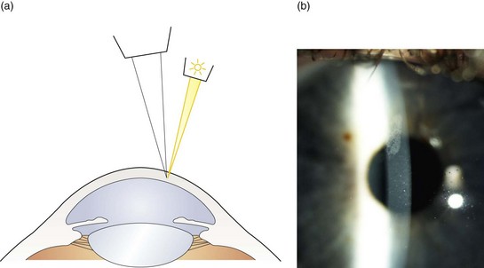
Fig. 7.1 (a) Diagram illustrating the position of the illuminating and viewing systems when using direct illumination. (b) A parallelepiped section of the cornea showing an irregularity above the corneal apex.
(a) Eyelids and lashes: Examine the superior eyelid and lashes first using the scanning procedure described above. This can be easier with the patient’s eyes closed. Examine the inferior lid and lashes in the same manner, while also examining lid apposition to the eye and meibomian gland appearance (section 7.3.3). Assess the lid for anomalies including an abnormal lid position (e.g., ptosis, entropion, ectropion), redness, inflammation, ulcers and growths. Inspect the lashes for colour (e.g., white), areas where the lashes are missing or misdirected and the presence of scales.
(b) Conjunctiva: Ask the patient to look upwards while you pull the lower eyelid gently downward to expose the lower fornix for examination. Examine both the bulbar and palpebral conjunctiva using a scanning process. Next ask the patient to look downwards and gently pull up the upper eyelid, thereby exposing the superior bulbar conjunctiva for examination. Finally ask the patient to look in right and then left gaze to allow examination of the entire conjunctiva, plica and the caruncle.
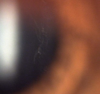
(c) Cornea and tear film: Use the scanning process to examine the cornea in three sweeps: inferior, central and superior. Examine the inferior cornea by having the patient look up and the superior cornea by having the patient look down while holding up the upper eyelid. With increasing experience you will be able to look at both the area illuminated (direct illumination, Figure 7.1) and the area just outside the area of illumination (indirect illumination, Figure 7.2, examples in Figures 8.12, 8.16). It can be useful to assess the tear film after a blink and note the quantity and type of debris if any. You can increase the width of the section of stroma seen by increasing the angle between the microscope and illumination system. You can obtain greater detail by increasing the magnification.
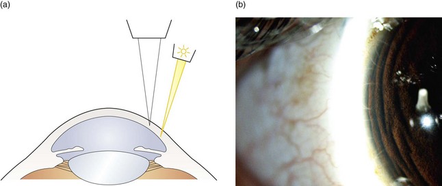
Fig. 7.2 (a) Diagram illustrating the position of the illuminating and viewing systems when using indirect illumination. (b) Corneal nerve fibres seen in indirect illumination.
(d) Assessment of the tear meniscus: The height of the tear meniscus can be estimated by decreasing the height of the slit-lamp beam to one millimetre and then judging the relative height of the meniscus at the lower lid margin as a proportion of the beam height.
(e) Iris: Examine the iris with direct illumination by moving the joystick towards the patient. Take note of the depth of the anterior chamber and the shape of the pupil.
(f) Lens: For a non-dilated pupil the illumination angle must be reduced until an optic section of the lens is just seen. This may be as small as 15° for an elderly patient with a small pupil. Further discussion of slit-lamp assessment of cataract under mydriasis is provided in section 8.4.
(g) Anterior vitreous: Moving the joystick further towards the patient allows viewing of the anterior vitreous with a parallelepiped when the pupil is dilated. To look for anterior vitreous floaters (Figure 7.3), it can be useful to ask the patient to look up, look down and then straight ahead, so that the opacities become visible as they float through the field of view (see online video 8.1) .
.
7.2.3 ‘Specialised’ slit-lamp techniques
 If an abnormality/anomaly is suspected from the case history or detected during a routine slit-lamp examination, one or more of the following illumination techniques may be used. With experience many or all techniques are used in fast succession. The slit-lamp magnification can be varied to examine the anomaly more carefully noting its size, shape, appearance, depth and location.
1 Optic section
This is a type of direct illumination in which the illumination beam is narrowed to allow a judgement of depth of any abnormalities within the cornea or lens (Figure 7.4). For example, it can be used to judge the depth of a foreign body in the cornea, whether an opacity is anterior or posterior cortical or subcapsular and is the technique used to grade nuclear lens opacity (section 8.4).
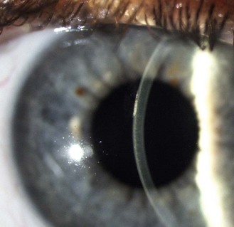
Fig. 7.4 A corneal section indicating that the corneal abrasion shown in Figure 7.1 is in the corneal epithelium.
1. Set the illumination system at approximately 45° from the microscope using low to moderate magnification (~10×).
2. If the area of the cornea/lens you wish to view is temporal, place the illumination on the temporal side and if it is nasal, place it on the nasal side.
3. Narrow the beam to the narrowest possible width and sharply focus on the cornea/lens using the joystick. As you have greatly narrowed the beam, you need to increase the slit-lamp illumination using the rheostat.
4. A slice of the cornea/lens should now be visible (cornea, Figure 7.4; lens, Figure 7.5; nuclear cataract, Figure 8.22). If the illumination system is temporal to the viewing system, the corneal epithelium or anterior lens will be on the temporal side of the image with the corneal endothelium or blurred posterior lens on the nasal side.
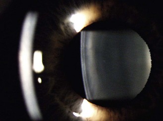
Fig. 7.5 An optical section of the lens anterior cortex (on the left side within the pupil) and lens nucleus (central). The posterior cortex is blurred and on the right side of the pupil. The blurred arc to the left is the out-of-focus cornea.
5. To view the posterior lens, the joystick needs to be moved further forward and the angle of the illumination system may need to be reduced further, depending on the pupil size.
6. The section of corneal stroma can be broadened by increasing the angle between the microscope and illumination system. The focusing should be precise enough to allow the graininess of the stroma to be visualised.
7. Once the object of interest is identified, increase the magnification to obtain greater detail.
2 Indirect illumination
This technique (Figure 7.6) is used to view areas that become bleached with excessive light using direct illumination, such as fine blood vessels at the limbus and microcysts. It is also used to look for iris features such as the outer rim of the iris sphincter.
1. Use a 1–2 mm parallelepiped, low to moderate magnification (~10×) and set the illumination system at ~45° from the microscope.
2. Rather than focus on the illuminated area (direct illumination), simply direct your gaze just outside the area that is illuminated (indirect illumination). Subtle abnormalities can be seen using light scattered by the cornea away from the main area of illumination.
3. Increase the magnification as required.
4. The technique can also be used after decoupling the illumination and viewing systems.
3 Specular reflection
When learning this technique, it is best to start by attempting to obtain an image of the anterior lens surface by specular reflection (Figure 7.7).
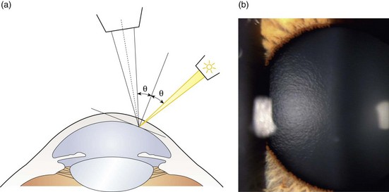
Fig. 7.7 (a) Diagram illustrating the position of the illuminating and viewing systems when using specular reflection to view the corneal endothelium. (b) Specular reflection from the anterior surface of the lens showing its orange peel appearance.
1. Set the illumination system at approximately 30° to 45° from the microscope, using a moderately wide 2–3 mm parallelepiped. Look through the eyepieces and focus the parallelepiped on the anterior lens.
2. Change the angle of illumination until the reflection of the instrument lamp is seen from the lens surface. This occurs when the angle of incidence equals the angle of reflection from the lens (Figure 7.7a).
3. View the orange peel textural appearance of the anterior lens (Figure 7.7b) to the side of the bright reflex.
4. To examine the tear film and epithelium, set the illumination system at approximately 45° to 60° from the microscope, using a moderately wide 2–3 mm parallelepiped. Look through the eyepieces and focus the parallelepiped on the cornea. Ask the patient to blink and use the particles floating in the tear film to help you focus.
5. Change the angle of illumination until a bright reflection is seen from the precorneal tear film. This occurs when the angle of incidence equals the angle of reflection from the cornea. This can also be obtained by moving the illumination/microscope system laterally until the two angles are equal.
6. To examine the endothelium, set the magnification to about 16× with a fairly wide 2–3 mm parallelepiped and initially focus on the tear film.
7. Alter the illumination angle and/or lateral position of the slit lamp until the bright corneal reflexes (Purkinje images) fall on top of the corneal section. There should be two reflexes: On the epithelial side of the corneal section there should be a bright white reflex from the tear film (conjugate with the epithelium) and on the endothelial side a less bright, slightly yellowed reflex from the endothelium. You may need to alter the angle of illumination very slightly to separate the two reflections.
8. Increase the magnification to about 40× and move the joystick slightly forward to focus on the endothelium. If you then look to the side of the dull endothelial slightly yellowed reflex (nasal or temporal to the reflex depending on the position of the illumination system) the duller picture of the endothelial hexagonal cells will be in view.
4 Eyelid eversion
1. Ask the patient to look down and grasp the superior eyelashes and pull them slightly away from the eye. It can be useful to press a cotton bud onto the superior lid to lift it away from the inferior lid, making it easier to grab just the superior lashes.
2. Gently press down on the superior margin of the tarsal plate at the crease using a cotton swab (or the index finger or thumb of the other hand), and at the same time pull the eyelashes up and over the cotton bud. This technique will evert the eyelid to permit viewing of the superior palpebral conjunctiva (Figure 7.8) using a parallelepiped.
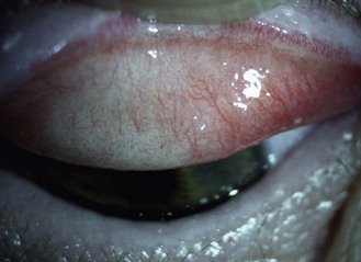
3. To re-evert the eyelid, hold the eyelashes and ask the patient to look up and gently pull the eyelashes away from the eye.
4. To evert the lower eyelid, pull the eyelid down and press under the eyelid margin while moving your finger upwards. The eyelid will evert over your finger.
5 Retro-illumination from the iris
This technique (Figure 7.9) is used in the examination of corneal vessels, epithelial oedema, pigment deposits or keratic precipitate on the endothelium and small scars on the cornea using light reflected from the iris. Opaque features appear dark against a light background.
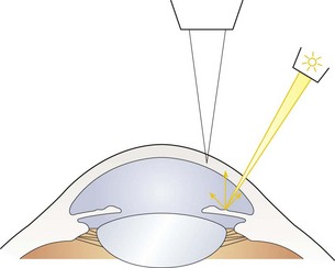
Fig. 7.9 Diagram illustrating the position of the illuminating and viewing systems when using retro-illumination from the iris.
1. Use a 1–2 mm parallelepiped with low magnification and set the illumination system to an angle of about 45°.
2. If it is possible to view the abnormality in direct illumination, bring it into focus and then lock the joystick position.
3. Decouple the illumination and viewing systems, direct the light onto the iris and view the structure against the light reflected from the iris. The magnification can be varied as necessary.
6 Retro-illumination from the fundus
This is a commonly used technique to examine iris disorders and cataracts using light reflected from the fundus. Cataracts are seen as dark opacities against the red background glow from the fundus (Figures 7.10, 8.20–8.24) and it is a particularly useful for examination of cortical and posterior subcapsular cataracts (section 8.4). Retro-illumination can also be used to detect iris abnormalities such as peripheral iridotomies and loss of pigment (iris transillumination, Figure 7.11). In this case, the red glow of the fundus is seen through the iris. The shape and location of the defects can help in identifying the cause of the transillumination.
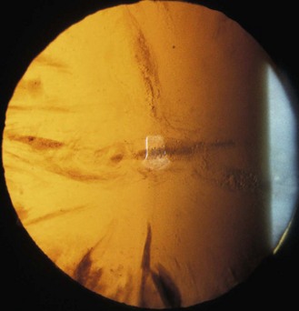
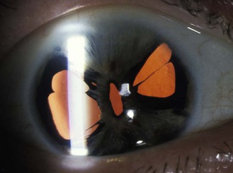
Fig. 7.11 Iris transillumination. Loss of localised iris pigment is shown by the red fundal glow appearing through parts of the iris when light is shone through the pupil. (Courtesy of Dr David Williams, University of Waterloo.)
1. Use a 1–2 mm parallelepiped with low magnification and set the illumination system to an angle of 0°. Adjust the beam height to the height of the pupil.
2. Focus on the iris or lens as appropriate.
3. You will only be able to focus the anterior or posterior part of the lens at any one time. You can gain an approximate focus on the anterior lens by focusing the iris. To focus the posterior lens you will need to push the joystick forwards (towards the patient). To gain a retro-illumination image of the lens with an undilated small pupil, you may need to decouple the instrument slightly and alter the angle of illumination by a small amount.
4. Observe any illumination coming through the iris. While lens opacities are best observed with the pupil dilated, iris transillumination is best observed before dilation.
7 Sclerotic scatter
Sclerotic scatter involves observing the cornea while the illumination is directed at the limbus. The light is totally internally reflected in a healthy cornea and creates a glowing halo of light where it escapes from the opposite limbus (Figure 7.12).
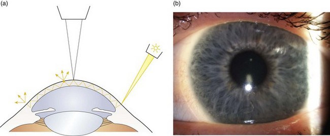
Fig. 7.12 (a) Diagram illustrating the position of the illuminating and viewing systems when using the sclerotic scatter technique. (b) Sclerotic scatter showing an S-shape of contact lens deposits.
1. Turn off the room lights to keep the surrounding light levels as low as possible so you can observe subtle amounts of light scatter.
2. Set the magnification at about 10× and use a 1–2 mm slit at about 45°. Focus the central cornea by ensuring the particles in the tear film are focused. Asking the patient to blink will move the tear film debris making them easier to find. Lock the slit-lamp position to ensure the viewing system remains focused on the central cornea.
3. Decouple the illumination and viewing systems and from 45–60° on the temporal side, move the 1–2 mm slit onto the temporal limbus. Ideally, shorten the length of the slit so that it enters at the limbus. Any extra slit length can produce light scatter from the sclera that may reduce the visibility of subtle defects.
4. Although you can scan the cornea for areas of light scatter with the naked eye, it is preferable to view it using the decoupled slit-lamp viewing system. Iatrogenic damage due to novice contact tonometry or gonioscopy use, foreign bodies, scars and central corneal clouding due to rigid contact lens wear can all be observed with this technique.
8 Anterior chamber assessment
This technique is used to look for flare (i.e., protein) or floating cells in the anterior chamber (by using more magnification and a longer beam). The following procedure has been recommended by the Standardization of Uveitis Nomenclature Working Group.2
1. Turn off all the room lights and close your own eyes for a few minutes to start to dark-adapt.
2. Set the illumination system at approximately 45° from the microscope using moderate magnification (~16×).
3. Narrow the height and width of the beam to obtain a beam 1 mm by 1 mm in size. Move the beam to the centre of the pupil and focus in the anterior chamber midway between the anterior surface of the crystalline lens and the posterior surface of the cornea. Focusing forward and back within the anterior chamber will facilitate the viewing of cells.
4. Cells are a sign of active inflammation and should be counted in the grading process. Aqueous flare is the result of leakage of protein through damaged iris blood vessels and is graded by the degree of obscuration of the iris details.
9 Double eyelid eversion
1. Sterilise Desmarres Lid Retractor using an alcohol wipe.
2. Instil anaesthetic and fluorescein into the eye.
3. With the patient at the slit lamp, single-evert the upper eyelid. Use the Desmarres lid retractor to hook under the everted tarsus with the blade placed between tarsus and bulbar conjunctiva.
4. Gently pull up and out to expose the fornix.
5. Observe for any small foreign bodies using fluorescein and the cobalt blue filter on the slit lamp or irrigate the fornix in free space to try to dislodge any foreign bodies.
7.2.4 Recording
Normal appearance: If no abnormalities are detected, record ‘clear’ if the tissue is transparent, such as the cornea and lens. Otherwise record ‘No abnormalities detected’ (NAD) or ‘Within normal limits’ (WNL) or equivalent.
Anomalies/abnormalities: Record the size, shape, appearance and location of any abnormalities/anomalies using a diagram and a written description as well as digital imaging if available. In addition, observations such as fluorescein staining, corneal oedema, conjunctival anomalies (papillae, follicles), injection and vascularisation may be graded on a scale of 0 to 4+ with 0 being absence of a response, 1+ being trace response, 2+ being mild response, 3+ being moderate response and 4+ being severe response.
Cataracts: Unless digital imaging is available, record cortical and subcapsular cataracts by drawing them (Figure 7.13). The undilated pupil can be recorded as a dashed line on this diagram. If there are cortical opacities in both the anterior and posterior cortex, both should be recorded. Nuclear yellowing and opacification can be graded on a scale of 0 to 4+ with 0 being absence of opacity and 4+ being the most severe form of opacity. For more precise grading, a cataract grading system such as the LOCS III system may be used.3 In this type of system the cataract is graded on a decimal scale against standardised colour photographs.
Cells and flare: Cells in the anterior chamber are graded according to the number observed with grade 0 being <1 cell, 0.5+ being 1–5 cells, 1+ being 6–15 cells, 2+ being 16–25 cells, 3+ being 26–50 cells, and 4+ being >50 cells.2 Aqueous flare is graded from 0–4+ depending upon the visibility of the iris detail; with grade 0 being no flare, grade 1+ being faint flare, 2+ being moderate (iris and lens details remain clear), 3+ being marked (iris and lens details are hazy), and 4+ being intense (fibrous or plastic aqueous).
Contact lens complications: Contact lens complications can be graded by using the Centre for Contact Lens Research Unit (CCLRU) or the Efron grading scales (Section 5.6).4
7.2.5 Interpretation
A good understanding of the normal anatomy and physiology of the anterior segment and adnexa as well as the normal changes with age is required. Variations in normal appearance of the anterior segment and changes with age are discussed in Chapter 8.
7.2.6 Most common errors
1. Not positioning the slit lamp so that the patient is leaning forward into the chin rest. This often results in the patient not being able to maintain their forehead against the headrest, resulting in the image going in and out of focus.
2. Not focusing the eyepieces to compensate for your refractive error.
3. Not increasing the brightness when narrowing the beam or using a filter.
4. Not maintaining a sharp focus as the beam is swept across the eye.
5. Not developing a smooth, logical routine that can be repeated.
7.3 Tear film and ocular surface assessment
The tear film is usually assessed during the slit-lamp examination of the anterior segment, and is specifically indicated in those wearing or wishing to wear contact lenses (Chapter 5), patients who have undergone or wish to undergo refractive surgery and patients with any symptoms of dry eye or a history that might suggest susceptibility (e.g. patients taking medications that include beta-blockers, antihistamines, oral contraceptives and acne medications, and smokers).5 The incidence of dry eye is increased following laser refractive surgery and nearly half of contact lens wearers report symptoms of dryness.6,7 Dry eye is a multifactorial disease that results in symptoms of discomfort, visual disturbance and tear film instability with potential damage to the ocular surface and is accompanied by increased osmolarity of the tear film and inflammation of the ocular surface.8 It is classified based upon aetiology as either aqueous tear-deficient or evaporative. Aqueous deficient dry eye includes Sjögren syndrome (autoimmune) and non-Sjögren syndrome dry eye and evaporative types are classified according to intrinsic causes (e.g., meibomian gland dysfunction) and extrinsic causes (topical drug preservatives, contact lens wear and ocular surface disease such as allergy).8 Symptoms commonly include irritation, dryness, foreign body sensation, burning, gritty sensation, transient blurring of vision, stinging pain, epiphora and contact lens intolerance. Less commonly mentioned symptoms include haloes around lights (especially at night), excessive tearing, stringy mucus discharge, redness, photophobia, itching and asthenopia. Patients often report closing their eyes to obtain some relief.
The international standard criteria for dry eye diagnosis is symptom assessment, interpalpebral surface damage, tear instability and tear hyperosmolarity. Although tear hyperosmolarity is mentioned as part of the criteria for diagnosis, it is currently impractical to measure in the clinical setting.9 Assessments appropriate for primary care would include symptom recording, including by standardised questionnaire, lower tear meniscus height, tear break-up time, tear volume by Schirmer or phenol red thread test, grading of conjunctival and corneal fluorescein staining and meibomian gland expression.7
Lacrimal occlusion can also be useful for the patient with marginal dry eye who wishes to continue wearing contact lenses, as well as for short-term occlusion during the healing process after ocular surgeries such as LASIK.6,10 Patients must be evaluated for the suitability for use of punctal or intracanalicular plugs as they are relatively expensive and reversal of the occlusion may be difficult in some cases if patient selection was inappropriate and excess tearing or complications occur. Temporary occlusion with dissolvable collagen plugs is a relatively inexpensive diagnostic test which allows the determination of suitability for therapeutic occlusion options.
7.3.1 Comparison of tests
Ocular surface damage caused by dry eye can be assessed using various vital dyes such as fluorescein, lissamine green and rose bengal. Fluorescein, which can pool in an indentation and is taken up by damaged cells and adheres to the surface of cells is the standard assessment for ocular surface damage.11,12 Lissamine green exhibits staining properties that are similar to rose bengal, but with significantly less toxicity and discomfort.13 Indeed, now that lissamine green is in widespread use, rose bengal tends to be rarely used in primary eyecare and is reserved for assessing more severe dry eye cases. Lissamine green stains dead and devitalised cells along with mucin but is not toxic to healthy cells. It is particularly useful for viewing more subtle conjunctival damage, in suspected marginal dry eye, patients with ocular allergies and current or potential contact lens wearers.
Tear break-up time (TBUT) is fast, easy to perform and comfortable for the patient. It requires equipment that is standard to optometric practice such as a biomicroscope with a cobalt blue filter and sodium fluorescein. The main disadvantage of the technique is that it is intrinsically invasive. In addition, a localised corneal surface abnormality will typically produce a break-up of the tear-film in that location and can suggest a falsely low TBUT. However, although a wide variability of the TBUT is present in normal individuals, a TBUT shorter than 10 sec has sufficient specificity to screen patients for evidence of tear film instability.14
Evaporative dry eye can be assessed with meibomian gland evaluation, the evaluation of lid and blink dynamics and lid anomalies causing poor lid closure. Aqueous deficient dry eye can be detected using tear flow/volume tests, such as the assessment of the tear meniscus and the Schirmer and phenol red thread tests.7 Note that these conditions are not mutually exclusive as meibomian gland dysfunction is present in 70% of patients with aqueous-deficient dry eye.14 The phenol red thread test is very easy to perform and patients generally tolerate it well as only a soft thread is touched to the lid and the results are obtained in 15 seconds per eye. Due to the relatively quick assessment, it is useful for examining the tear volume before and after insertion of lacrimal occlusive devices. The Schirmer tear test uses a 5 by 35 mm strip of filter paper to measure basic and reflex tear secretion when used without anaesthetic. The Schirmer test is used in severe dry eye patients and as part of the definition of Sjögren syndrome, although research has suggested that it has limited reliability and validity.14–16
Short-term dissolvable collagen plugs are the only diagnostic test that determines whether more permanent punctal and intracanalicular plugs are suitable for the patient. They imbibe water and expand in the canaliculus to approximately two times their diameter, then proceed to dissolve in 4–7 days. After approximately one week, the patient is asked to return and subjective and objective assessments of dry eye are compared pre- and post-insertion of the plugs. The only decisions to be made are the number of implants required and which canaliculi to occlude. More than one trial of collagen implants may be required to prove to you and/or the patient that (semi-)permanent plugs will be a useful therapeutic option for their particular case. For example, patients with poor corneal sensitivity from nerve damage or chronic ocular surface disease may be unable to detect an improvement in comfort during the course of the collagen trial, and therefore may feel that long-term occlusion options will not be helpful for them. In those cases, the objective signs are more helpful in determining suitability and therefore repeated trials may be considered to monitor the corneal and conjunctival health to determine if occlusion is advisable. It is also generally true that a single collagen plug (even the largest size that can fit into the punctal opening) is often insufficient to appropriately occlude a canaliculus and therefore may generate a false negative trial. This is because the diameter of the canaliculus may be unrelated to the size of the punctum and a single plug may migrate out of the system before it has had the opportunity to imbibe water and occlude the drainage. Similarly, some clinicians occlude only the inferior canaliculi for the diagnostic test. While this may be appropriate in some circumstances, it is also more likely to generate a false negative diagnostic test. Full occlusion, even if it generates some degree of epiphora, is generally preferred and is short-lived. Measurement of tear thinning time suggests that superior plug insertion may not be necessary and that occlusion of the lower punctum is sufficient, although occlusion of both prolonged the preservation of tear volume.17
7.3.2 Procedure for corneal and conjunctival staining
1. Wet the tip of a fluorescein strip with sterile saline solution. Be careful not to contaminate the saline by touching the strip to the tip of the bottle. Shake excess fluid from the strip over a sink (too much fluid will delay the time to maximum fluorescence and may drip onto and stain the patient’s lids and cheeks).
2. Ask the patient to look up and touch the strip to the inferior bulbar or tarsal conjunctiva, being careful not to touch the cornea. Do not use a sweeping movement to ‘paint’ the conjunctiva as it can provide too much fluorescein and create unnecessary discomfort for the patient. The strip can also be touched to the upper bulbar conjunctiva, but this has the disadvantage that if the patient blinks or attempts to blink, the eye will rotate upwards (Bell’s phenomenon) and the strip may scratch the superior cornea. Ask the patient to blink several times to allow the fluorescein to spread across the cornea. Remove any excess fluorescein using a tissue and be careful not to spill the dye on the patient’s clothes as a stain will result.
3. With the patient at the biomicroscope, observe the cornea with cobalt blue light and medium magnification. When you are using the cobalt blue light, you will need to increase the illumination. A Kodak Wratten number 12 yellow gelatin filter held in front of the biomicroscope viewing system will facilitate the view by filtering out the reflected blue light. Newer slit lamps have this filter as a built-in option over the observation system. Observations should be made within 10 min of instillation of the dye otherwise intercellular diffusion surrounding a lesion may mask its exact nature.
4. It can be useful to examine the eye using both diffuse illumination and then a wide parallelepiped beam, altering the angle of the illumination throughout.
5. In addition to the standard examination, evert the upper eyelid to inspect its inner margin for staining due to lid wiper epitheliopathy caused by friction, secondary to dry eye.9 Also inspect the lower lid margin for parallel bulbar conjunctival folds.18
6. Soft contact lens wearers can replace their lenses after a biomicroscopic investigation using fluorescein or lissamine green as long as the dye is irrigated out of the eye using saline prior to lens reinsertion. Otherwise irrigation is not necessary. An alternative is to use Fluorexon which is a high molecular weight fluorescein that will not penetrate into a soft contact lens.
7.3.3 Procedure for meibomian gland evaluation
1. Assessment should be done after other tests used in the diagnosis of ocular surface disease.7
2. With the patient at the biomicroscope, use white light and medium magnification to inspect the lower eyelid margins.
3. Look for stenosis and closure of the meibomian gland orifices, inspissated (thickened and blocking the glands) secretions and frothing of the tears on the eyelid margins. The lids should be examined closely for telangiectasis of vessels on the lid margin, notching of the gland openings and migration of these openings towards the posterior surface of the lids, all indicative of chronic disease.
4. Pull the lower eyelid down and look for concretions (section 8.2.8) in the palpebral conjunctiva.
5. Inform the patient that you are going to press on his or her eyelid and that they will feel some pressure. With the patient looking up, apply moderate pressure on the lower eyelid margins near the eyelashes, while observing the meibomian gland orifices and assess the expressibility and secretion quality. Clear fluid should be expressed. If this is not the case apply pressure over the central third of the upper and low lids to determine the extent and severity of the dysfunction.7
6. Capping of the orifices, a cheesy secretion on expression and frothing of the eyelid margins indicates meibomian gland dysfunction. Another method of assessing the meibomian gland function is to determine the position of the Marx line which is a clear line running along the lower lid margin after fluorescein or lissamine green is instilled into the eye. In normal eyes this line is located on the conjunctival side of the meibomian gland orifices and in meibomian gland dysfunction it is located on the cutaneous side of the orifices.19
7.3.4 Procedure for tear break-up time (TBUT)
 TBUT is used to assess the stability of the tear film between blinks. Dry spots appear in the tear film that are thought to form by evaporation and retraction of the tear film after each blink and by diffusion of the superficial lipid through the aqueous layer to the mucin surface. Topical anaesthetics should not be used prior to TBUT measurement, as this may cause a further reduction in TBUT.
1. With the patient at the biomicroscope, instil fluorescein into the tear film and ask the patient to blink several times.
2. Examine the tear film with a wide 2–3 mm parallelepiped and low magnification. Switch to the cobalt blue filter on the slit lamp. The tear film should appear as a fine green film due to the fluorescein.
3. Ask the patient to hold their eyes open without blinking.
4. From the time of the blink, time how long it takes in seconds before dark spots or streaks appear in the even green tear film after a blink. The use of the Kodak Wratten yellow filter number 12 held over the observation system is helpful for this evaluation.
5. If the patient blinks before 10 seconds have passed then the measurement cannot be made and the procedure must be re-started.
6. Repeat the measurement at least once and take an average.
7. If the tear film breaks up immediately and consistently in the same location there may be an epithelial basement membrane defect in that location on the cornea. The TBUT should be repeated, not considering this defect, to get an indication of tear film stability.
7.3.5 Procedure for non-invasive break-up time (NIBUT)
NIBUT or tear thinning time measurements involve projecting a pattern on to the tear film and observing the specular image. Keratometer mires are commonly used in clinical practice but grids are also available and the tearscope is a commercially available test for measuring NIBUT.14,20
1. The illumination of the room should be low to provide the best image contrast.
2. With the patient’s head in position on the chin rest of the slit-lamp biomicroscope or the keratometer, focus the instrument so that a clear view of the pattern is seen. If using a keratometer, the mires should be central positioned and sharply in focus.
3. Instruct the patient to blink fully and normally, and then to hold their eye wide open and not blink until instructed.
4. The time between the last complete blink and the first indication of pattern break-up is recorded with a stop-watch.
7.3.6 Procedure for phenol red thread test
1. The test may stimulate some degree of reflex tearing and should be undertaken prior to manipulation of the eyelids or to instillation of any fluid or dye into the tear film.
2. Instruct the patient to look up slightly and blink normally during the test.
3. Remove the threads by gently peeling the plastic film covering from the unsealed end of the aluminium sheet. Make sure that the folded 3 mm end of the thread is bent open at an angle that allows for easy placement onto the palpebral conjunctiva.
4. Pull the lower eyelid away from the globe slightly and place the folded 3 mm portion of the thread on the palpebral conjunctival junction, approximately ⅓ of the distance from the lateral canthus of the lower eyelid with the eye in the primary position.
5. Begin timing as soon as the thread touches the tear layer.
6. After 15 seconds, gently remove the thread.
7. Measure the length of the red portion of the thread in mm from the very tip (ignoring the fold).
8. Since tear volume can vary, reliability can be improved by repeating the test on different days. It may also be helpful to ask the patient if they could feel the thread during testing, as it could be indicative of a reflex tearing component to the measurement. Excessively high measures (approaching 30mm+) should be repeated.
7.3.7 Procedure for Schirmer tear test
1. The test may stimulate some degree of reflex tearing and should be undertaken prior to manipulation of the eyelids or to instillation of any fluid or dye into the tear film.
2. Bend the round wick end of the test strips at the notch approximately 120° before opening the sterile pouch. Peel back the pouch and remove the strips. Only handle the strips by the non-wick ends to avoid contamination.
3. Have the patient look up and gently pull the lower eyelid down and temporally. Place the bent hooked end of the strip at the junction of the temporal and central third of the lower eyelid margin. The strip should not touch the cornea when the eyelid is released. Release the eyelid and have the patient continue to look up, blinking normally. The patient can close his or her eyes if this is more comfortable but should not squeeze the eyes shut. Both eyes should be measured at the same time.
4. Note the time of insertion. Remove the strip after 5 minutes or when it is completely wet, whichever comes first. Measure the wetted portion of the strip from the notch towards the flat end in mm. Record this value.
7.3.8 Procedure for diagnostic collagen plugs

1. Ask the patient whether they have any allergy (or opposition) to (bovine) collagen, silicone or other materials or anaesthetics. Discuss the procedure, any sensations the patient might experience during the procedure, and any potential adverse effects. Obtain informed consent.
2. Disinfect jeweller forceps.
3. Inspect the puncta and choose the largest implant size that seems likely to fit into the punctal opening without punctal dilation. The 0.40 mm plug size is the most commonly used. Choosing a plug size that is too small (e.g. the 0.3 mm size) will often result in a false negative trial due to the plugs migrating straight through the system.
4. Seat the patient comfortably at the slit-lamp biomicroscope or in an examination chair capable of reclining. In the latter case, a loupe may be used for magnification.
5. Do not anaesthetise the puncta and ocular surface as it reduces the ability of the patient to detect an immediate improvement in ocular surface symptoms and the procedure is generally well tolerated by patients.
6. Open the sterile packet and grasp a single implant from the foam packet (Figure 7.14a), preferably very close to the end of the plug and with it oriented approximately perpendicular to the forceps. This can be undertaken either using the biomicroscope magnification or outside the slit lamp.
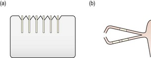
Fig. 7.14 Diagrammatic representation of (a) a set of six collagen plugs in their foam packaging; (b) hydrated collagen plugs in the canaliculi.
7. Inferior plug insertion: Inferior plug insertion is generally easier than superior. Instruct the patient to look upwards and temporally and with a finger of the opposite hand to the forceps pull the lower eyelid away from the globe just enough to expose the punctum. Pulling the lid down and away too much will bend or kink the canaliculus.
8. Place the implant partially into the opening vertically, then pull laterally on the eyelid to straighten out the vertical and horizontal portions of the canaliculus. With the canaliculus straightened, advance the plug as far as possible, preferably almost all the way in, and release the forceps. Keep the eyelid in the same position, close the tips of the forceps and gently push the rest of the implant into the opening until it disappears below the punctal ring. No part of the plug should be visible at the punctal opening.
9. Generally, use two implants in the inferior and one in the superior canaliculus to effectively occlude the system for diagnostic purposes (Figure 7.14b). Single collagen implants may flush or reflux out of the system before they expand. Three implants in a canaliculus minimises the likelihood of the plugs refluxing out or flushing through.
10. Superior plug insertion: Instruct the patient to look downwards and temporally for the upper plug insertion. Using the thumb of the opposite hand to the forceps, press in towards the globe on the upper nasal lid. The upper punctum should evert from the eye. Again, try not to kink the canaliculus. Insertion proceeds as per the inferior plug insertion described above.
11. Repeat the phenol red thread test (section 7.3.6) after the patient has settled for a few minutes after plug insertion.
12. Ask the patient to keep a diary of symptoms over the next 5–10 days, and arrange a follow-up appointment in 7–10 days. If symptoms and tear film and ocular surface evaluations suggest that (semi-)permanent occlusion is appropriate, discuss the various options for therapeutic occlusion.
7.3.9 Recording
Dye staining. The staining areas on the cornea and the conjunctiva should be both described and drawn on a diagram of the anterior segment or photographed. The staining should be classified and differentiated from other causes (Figure 7.15). The CCLRU scale can be used to grade staining.
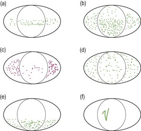
Fig. 7.15 Characteristic fluorescein staining patterns. (a) Band superficial punctate staining (SPS) due to conditions such as mild dry eye or exposure of the region. (b) More severe band SPS possible in severe dry eye. (c) Rose bengal staining in dry eye. (d) Diffuse SPS due to conditions such as adenoviral and staphylococcal keratoconjunctivitis and reactions to diagnostic or therapeutic eyedrops. (e) Inferior SPS due to conditions such as staphylococcal blepharoconjunctivitis and exposure of the region. (f) Foreign body or trichiasis (particularly when in the inferior cornea) tracks.
Tear break-up time. The TBUT or NIBUT value should be recorded in seconds for each eye individually. Indicate the method that was used to determine this value. For example, NIBUT with grid pattern, 10 s RE (OD), 12 s LE (OS).
Phenol red thread and Schirmer tests. Record the distance in mm that the thread is red (phenol red test) or that the strip is wet (Schirmer test) for each eye. For example:
Diagnostic collagen plugs. Record the type and number of plugs inserted into each canaliculus and the symptoms, ocular lubricant use and the results of all dry eye assessment tests before and after their use. The results of the phenol red thread tear volume test (section 7.3.6) before and just after insertion of the plugs are of particular importance to determine if occlusion has been achieved. Consider adding additional plugs per canaliculus (up to three) if the phenol red thread results are not increased from the pre-plug values.
7.3.10 Interpretation
Dye staining. Surface damage on both the cornea and conjunctiva is revealed with fluorescein staining and staining due to dry eye has a characteristic distribution confined to the interpalpebral area of the ocular surface. Lissamine green staining is dose-dependent, therefore if a very small amount is used the staining will be very minimal.21 Temporal and nasal interpalpebral bulbar conjunctival lissamine green staining is predictive of dry eye. With rose bengal it can be difficult differentiating its red stain from the underlying hue in patients with inflamed red eyes.
Tear break-up time. The normal TBUT is between 15 and 45 seconds and a break-up time of less than 10 seconds is indicative of an unstable tear film. Normal NIBUT measured with a keratometer is between 28 and 60 seconds and a break-up time of less that 10 seconds is indicative of an unstable tear film.22,23 TBUT measurements are significantly lower than NIBUT values, and the disparity is smaller for short break-up times associated with poor tear quality.24 Normal TBUT and NIBUT measurements are sometimes limited by the patient’s ability to keep their eyes open and not blink.
Phenol red thread and Schirmer tests. For the phenol red thread test, a measurement of <10 mm wetting represents true dryness, while 10 to 20 mm wetting is considered borderline, and >20 mm is generally considered normal. Measurements in the high 20s or 30s is most likely due to reflex tearing. For the Schirmer test, a measurement of 10–15 mm or more without anaesthesia is regarded as normal tear production. A value of less than 5 mm represents a significant aqueous dry eye. Several measurements should be made on repeated visits and averaged to obtain as accurate a result as possible.
Diagnostic collagen plugs. If a positive response is obtained with collagen plugs, a more long-lasting type of occlusion is indicated. If occlusion is not sufficient to relieve symptoms to an acceptable level and ocular signs remain, occlusion of the superior canaliculi may be considered. Before placing (semi-)permanent implants in the superior system, perform a second diagnostic test in the superior canaliculus with collagen plugs. If this procedure also shows benefit in either symptoms or ocular surface signs, consider a more long-lasting occlusion method for the superior puncta or canaliculi. If bothersome epiphora is reported during the second diagnostic test, superior occlusion is not advised.
7.3.11 Most common errors
1. Performing TBUT with a fluorescein/anaesthetic combination.
2. Spilling fluorescein on the patient’s lids or clothes.
3. Touching the cornea with a fluorescein strip or wiping the fluoret against the conjunctiva, causing discomfort and reflex tearing.
4. Not obtaining a sharply focused image of the grid or mires before measuring NIBUT.
5. Performing the red thread or Schirmer test after manipulation of the lids, instillation of diagnostic drugs or dyes, or applanation tonometry.
7.4 Assessment of the lacrimal drainage system
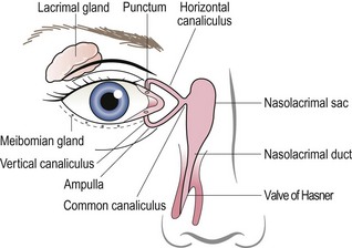
Many patients complain of excess tearing. True nasolacrimal system obstruction (epiphora) must be differentiated from reflex tearing associated with conditions such as dry eye. Obstruction may occur anywhere in the pathway from the ocular surface to the nose (Figure 7.16). The most common locations include the punctum, the vertical or horizontal canaliculus, the common canaliculus and the nasolacrimal duct. The latter two listed are more likely to cause significant tearing as they affect overall drainage, whereas a single punctum or canaliculus will reduce outflow through one of the two channels but will not impede it completely. If nasolacrimal system obstruction is suspected, an assessment of the lacrimal drainage system is required.
7.4.2 Initial procedures
1. Try to assess if the tearing is due to a nasolacrimal obstruction or eyelid abnormality such as ectropion or entropion or due to paradoxical reflex tearing from a dry eye or other ocular surface problem (intermittent tearing). Ask about any history of facial trauma and/or nasal surgery.
2. Explain the procedure and obtain informed consent. Encourage the patient to blink normally and not to squeeze the eyes during the procedure(s).
3. Ask the patient to blow their nose and clean it thoroughly with tissues.
7.4.3 Procedure for fluorescein dye disappearance test
1. Instil equal amounts of fluorescein in each eye and observe the patient for five minutes.
2. Compare the relative heights of the tear meniscus at the inferior margin of each eye and the degree of fluorescein spilling over the patient’s eyelids.
3. Do not allow the patient to blot the fluorescein as this might draw an excessive amount of fluorescein and tears out of the conjunctival sac. Wipe away any excess fluorescein dye which has spilled onto the patient’s cheek to avoid unnecessarily staining the skin.
7.4.4 Procedure for Jones 1 or primary dye test
1. Moisten two to four fluorescein strips with sterile saline and touch to the inferior nasal palpebral conjunctiva, introducing a large amount of dye and fluid into the conjunctival sac. False test results are more likely if insufficient dye is applied.25
2. Allow the patient to blink normally for five minutes. Again, ensure that fluorescein dye does not remain in contact with the facial skin long enough to dry.
3. Note that the dye disappearance test may be undertaken simultaneously with the Jones 1 test by observing the dye distribution and disappearance characteristics.
4. Instruct the patient to occlude the nostril on the unaffected side (if tearing problem is unilateral) or one nostril at a time (if tearing problem is bilateral) and blow into a white tissue.
5. Inspect the tissue for fluorescein using a Burton lamp or the cobalt blue light on the slit-lamp biomicroscope.
6. If no fluorescein is detected and especially if the dye was noted to have cleared from the eye other than over the lids onto the face, a false result may have been noted. Consider repeating the test or ask the patient to roll a sterile swab about 1 cm into the nose against the inferior turbinate. Check the swab for fluorescein with the cobalt blue light.
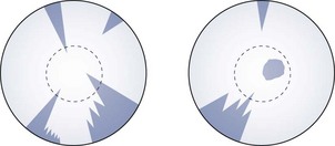
7. If fluorescein is recovered (Figure 7.17a) no further tests are required as the nasolacrimal system is patent. Reflex tearing from dry eye and other causes should be reconsidered. Dilation and irrigation may still be considered if it is thought that there may be a partial blockage that might be relieved with irrigation.
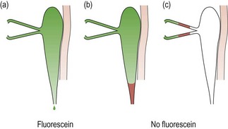
Fig. 7.17 Jones I test. (a) Fluorescein is recovered, indicating that the system is patent. (b) and (c) The absence of fluorescein indicates a blockage or stenosis in the system and the need for dilation and irrigation; (b) shows a lower system blockage and (c) an upper system blockage.
8. If no fluorescein is recovered (Figure 7.17b,c), there is either some degree of blockage of the drainage, there is a failure of the lacrimal pump mechanism, or a false test result was obtained, likely due to insufficient fluorescein being used.
9. Consider dilating the punctum on the affected side and repeating steps 1 to 5. If fluorescein is now recovered, the source of the poor drainage was likely stenosis of the punctum.
7.4.5 Procedure for dilation and irrigation
1. Prepare the instruments with appropriate disinfection of internal and external surfaces. Attach a reinforced 23-gauge cannula to a 3, 5, or 10 cc syringe.
2. Fill the syringe with 3 to 5 cc sterile saline. Push most of the saline through the cannula to thoroughly rinse the disinfectant, reserving approximately 1 cc for irrigation.
Dilation
3. Anaesthetising the surface and puncta are not required but are determined based on patient and practitioner preference. Anaesthetise the superior and inferior puncta with a cotton-tipped applicator soaked with anaesthetic (e.g. proparacaine). Have the patient open his or her eyes. Pull the lower eyelid out of apposition with the globe and place the soaked pledget firmly on the inferior punctum. Have the patient close their eyes for several minutes over the soaked bud such that both puncta come into contact with the applicator.
4. Recline the patient slightly in the chair, and direct their gaze out and away from the canaliculus being dilated/irrigated. For example, have the patient look superior temporally to irrigate the inferior system. Use a magnifying lens (loupe) if necessary.
5. Pull the inferior eyelid away from the globe and place a long-tapered dilator vertically into the inferior punctal opening (<2 mm).
6. If the punctum is tight around the dilator, gently roll the dilator back and forth between your fingers to begin to dilate the punctum.
7. Once the dilator is inserted 1–2 mm, advance the dilator a little further while pulling laterally on the eyelid to straighten out the canaliculus. Continue to roll the dilator back and forth while directing the tip of the dilator nasally towards the location of the opening into the common canaliculus (i.e. orientation of the dilator is now horizontal). Whitening of the punctal ring indicates expansion of the opening. Do not force the dilator too deeply into the canaliculus and retract if resistance is encountered or the patient experiences significant discomfort or a sharp pain.
8. If the punctum is not sufficiently enlarged or closes down before the cannula can be inserted, dilate again with the long tapered dilator and gently advance it further, again respecting the anatomy and the patient’s comfort.
9. The primary dye test (Jones 1) may be repeated after only punctal dilation; however, generally you will proceed to irrigation.
Irrigation
10. Insert the cannula immediately after dilating the punctum. If the punctum cannot be opened sufficiently to insert the cannula, consider a smaller gauge cannula or a wider dilation of the punctum.
11. Pull the eyelid away from the globe slightly and insert the cannula 1–2 mm vertically then pull the eyelid taut laterally to continue 1 to 4 mm into the horizontal canaliculus, as with the dilator. If the cannula meets with gentle resistance, this is termed ‘soft stop’, and the cannula should not be advanced further as an obstruction exists in the canaliculus. The ‘hard stop’ position indicates that the cannula has come into contact with the nasal bone. This can only be achieved with a sufficiently long cannula to transverse the vertical, horizontal and common canaliculi and the lacrimal sac (>10 mm advancement).
12. Reach up with the thumb of the hand not holding the cannula/syringe. While watching carefully that the position of the cannula is maintained (i.e. that it is not inadvertently advanced further into the canaliculus), apply pressure to the plunger to introduce a small amount of saline (less than 0.5 cc) into the system. Never force the fluid if resistance is encountered. If resistance is encountered, first withdraw the cannula and test that the cannula/syringe combination itself is not obstructed by pushing fluid through the syringe and cannula. Reintroduce the cannula.
13. Once a small amount of saline is introduced, the patient is asked to report when it is detected in the throat, at which time pressure on the plunger of the syringe is stopped and the cannula carefully withdrawn (go to step 15). Keep talking to the patient throughout the procedure to ensure that they remain still until the cannula is withdrawn safely.
14. If saline regurgitates from the canaliculus being irrigated, it is likely that this canaliculus is obstructed or stenosed.
15. If saline regurgitates from the contravertical punctum, a common canaliculus blockage should be suspected. Hold a sterile cotton-tipped applicator firmly on that punctum and try to irrigate again. Carefully withdraw the cannula.
16. Offer the patient a mint or lozenge as the saline can have an unpleasant taste for some patients.
7.4.6 Recording
Fluorescein dye disappearance: Record if the meniscus height is equal in each eye and if dye runs down over the patient’s cheek or disappears into the nasolacrimal drainage system. Relative speed of disappearance between the eyes is also relevant. Take note of the completeness of the blink, including apposition of the puncta, and the lid position.
Jones 1: Record whether or not dye was recovered on each side. Note that some sources label the presence or recovery of dye as ‘positive’ and absence of dye as ‘negative’, so that a ‘positive Jones 1 test’ means that the system is patent. This is opposite to the usual convention of a positive test result being one that indicates a problem, so it is best to record whether or not dye is recovered in each test in order to avoid confusion, e.g. dye recovered in left nostril (left nasolacrimal system patent).
Dilation and irrigation: Record whether or not the patient tasted salt or felt the solution in the throat. Also note if saline was regurgitated from the same canaliculus or from the contravertical canaliculus.
7.4.7 Interpretation
Fluorescein dye disappearance: If the heights of the tear meniscus are unequal, it implies that the eye with the larger meniscus may have impaired tear drainage. It is less likely that there is a unilateral poor meniscus due to dry eye or unilateral pseudoepiphora from reflex tearing from the dry eye.
Jones 1: If fluorescein is recovered, no further tests are required as the nasolacrimal system is patent. However, some clinicians may consider dilation/irrigating if they feel there is a chance to dislodge a partial obstruction. If no dye is recovered, this indicates either a partial or full blockage in the system, a failure of the lacrimal pump mechanism, or it could be a false positive. Insufficient fluorescein is the most likely cause of a false positive result.25 If mucopurulent effluent is recovered, irrigation should not be attempted as there is an active infection/inflammation.
Dilation and irrigation: Normally fluid should exit from the system and be noted by the patient in the throat. A blocked system will offer resistance to fluid injection or cause regurgitation from the contravertical punctum. No fluid flow in the throat indicates a complete obstruction. Fluid subsequently noted in the throat indicates that the obstruction was relieved or there had been a partial obstruction or a stenosis.
7.4.8 Most common errors
1. Instilling insufficient fluorescein or making inadequate attempts to recover fluorescein for the Jones 1 test can lead to false results.25
2. Not introducing the cannula quickly enough such that the punctum closes down after dilation, making it difficult to insert the cannula.
3. Failing to respect the anatomy of the canaliculi with the dilator/cannula during dilation/irrigation, leading to patient discomfort.
7.5 Anterior chamber angle depth estimation
7.5.1 Comparison of tests
The van Herick anterior angle assessment is a relatively quick and simple procedure and can be part of a routine assessment of the anterior eye using the slit-lamp biomicroscope. The superior angle is the narrowest and most likely to close. Although the van Herick angle assessment is unable to assess the superior angle, in most cases the technique is sufficient to indicate whether there is a danger of angle closure.26 Only if the angle appears narrow using this assessment is gonioscopy required to determine whether dilation is safe. The van Herick assessment is a conservative one in that many patients with a narrow angle as determined by the test can be safely dilated.27
7.5.2 Procedure: van Herick assessment

1. Seat the patient at the slit-lamp biomicroscope and set up the biomicroscope with magnification at the medium setting (~16×).
2. Explain the procedure to the patient and then ask them to look straight ahead.
3. Narrow the beam to an optic section (section 7.2.3) with the illumination system at 60° temporal to the microscope. Because you have narrowed the beam, you may need to increase its brightness.
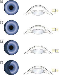
4. Move the illumination system temporally to the very edge of the temporal limbus, keeping the cornea in focus (Figure 7.18). It is important to move only until the first shadow is seen.
5. Judge the depth of the anterior chamber by the width of the optically clear space between the cornea and the iris. Compare this width to the width of the cornea (Figure 7.19). Record the result using a ratio or van Herick’s grading system.
6. Repeat the measurement on the nasal anterior chamber angle. You may have to rotate both the illumination and viewing systems (keeping them 60° apart) to ensure the illumination system avoids the patient’s nose.
7.5.3 Procedure: Shadow test angle estimation
1. Dim the room lights and ask the patient to look straight ahead.
2. Hold a penlight a few cms from the outer canthus and at an angle of 100° temporally in the horizontal plane of the patient’s right eye and rotate it around to 90°. The temporal side of the iris will illuminate.
3. Observe the nasal iris carefully and note how much of it is in shadow (Figure 7.20).
7.5.4 Recording
van Herick: Record the result as a ratio with the cornea being unity and the anterior chamber width being a fraction of the corneal width. Alternatively, van Herick’s grading system can be used (Table 7.2). If only one measurement is recorded, it can be assumed to be temporal. Examples:
Table 7.2
Van Herick’s anterior chamber angle grading system
| Van Herick grade | Cornea: anterior angle depth | Probability of angle closure |
| Grade 0 | Closed | 100% |
| Grade I | <1 : 1/4 | Very likely |
| Grade II | 1 : 1/4 | Possible |
| Grade III | 1 : 1/2 | Unlikely |
| Grade IV | 1:1 or greater | Impossible |
Shadow test: Grade the angle according to the percentage of the nasal iris that is in shade or use the equivalent grade (Table 7.3). For example:
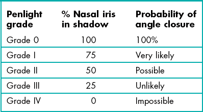
7.5.5 Interpretation
The angle should normally be grade III or grade IV (Figure 7.18). The prevalence of narrow angles of grade I and II is about 2%. If the angle is grade II or narrower, there is a risk of angle closure and the pupil should be dilated only if a gonioscopy examination indicates that it is safe to do so. Hyperopic eyes, being relatively small, tend to have smaller anterior angles while the larger, myopic eye tends to have larger anterior angles. The growth of the crystalline lens throughout life (before cataract surgery) means that elderly patients are much more likely to have a small anterior angle and children typically have large anterior angles. Note that early age-related cataract, particularly anterior and posterior subcapsular cataracts, typically lead to a thinner lens and a wider anterior angle.28
7.6 Gonioscopy
Specific indications for gonioscopy include:
• Narrow anterior chamber angles suggested by van Herick to assess the relative risks for pupillary dilation. Gonioscopy is the gold standard technique against which screening tests for narrow angles are compared.29
• Narrow (or closed) angle glaucoma including evaluation and documentation of peripheral anterior synechiae if present.29
• Primary open angle glaucoma (POAG) and risk factors for POAG (e.g. elevated intraocular pressure) to confirm ‘primary’ diagnosis.
• Secondary open angle glaucoma and risk factors (e.g. pseudoexfoliation, pigment dispersion, chronic uveitis) to contribute to determination of disease severity.
• Risk of angle neovascularisation (e.g. confirmed rubeosis iridis, and ischaemic posterior segment conditions including vein or artery occlusions and diabetic retinopathy).30
• Risk of angle recession post blunt trauma.
• Risk of intraocular foreign body.
• Congenital or acquired structural irregularities of the iris and anomalies of the anterior chamber (e.g. iris cysts or tumours, ectopic pupil).
• Post laser peripheral iridotomy to assess effect on angle depth.
Gonioscopy is contraindicated in patients who have experienced:
7.6.1 Comparison of different gonioscope lenses
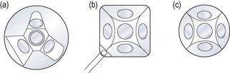
Scleral-type lenses such as the Goldmann 3-mirror lens (Figure 7.21) provide excellent optics and mirror placement allowing for the detection of subtle angle findings (e.g. early angle neovascularisation), which can be more difficult with the poorer image quality of corneal-type lenses. Scleral-type lenses also provide excellent lens stability on the eye once inserted and good eyelid control even with a patient with blepharospasm. This allows a better view in patients with significant loss of corneal transparency. The image may be more transient with corneal-type lenses as the tear film seal is disrupted easily if the lens is not maintained on the central cornea. The Universal lens also contains two additional mirrors angled for evaluation of the peripheral and midperipheral fundus as well as a central lens for evaluation of the vitreous and posterior pole (section 7.12).
All corneal-type lenses (e.g. Posner, Zeiss, Sussman; Figure 7.22) have a smaller (9 mm) and flatter area of contact on the cornea as compared to the scleral-type lenses and have four mirrors, all of which are angled to allow examination of the anterior chamber angle. The smaller, less concave surface enables gonioscopy without the need for a viscous coupling solution and essentially no lens rotation is required as all four mirrors are angled for gonioscopic assessment. The lens is easily inserted onto the cornea of a cooperative patient thus facilitating a relatively quick assessment, unlike the more challenging lens insertion and required coupling solution with scleral-type lenses. Corneal compressions can only be undertaken with corneal-type lenses and allows differentiation between appositional and synechial angle closure. Disadvantages of corneal-type lenses include the identification of an artificially wider angle if too much pressure on the cornea causes the angle to appear to widen. Corneal epithelial disruption may also occur if significant lens movement occurs on the corneal surface.
7.6.2 Goldmann 3-mirror (Universal) gonioscopy procedure (see summary in Box 7.1)

1. Describe the specific indications for gonioscopic assessment to the patient and outline the procedure: ‘I would like to use a contact lens on the front of your eye to examine the hidden part of the front of your eye. I will be putting a drop in your eyes to numb the cornea, so do not rub your eyes for at least half an hour or you could scratch your eye without feeling it.’ Obtain informed consent.
2. Lens preparation: Clean and disinfect the gonioscopy lens. Fill approximately two-thirds of the concave lens surface with a viscous coupling solution, ensuring no bubbles remain to interfere with the view.
3. Anaesthetise both eyes. Gonioscopy can be performed immediately following applanation tonometry so that additional anaesthetic is not necessarily required. Fluorescein does not interfere with the examination.
4. Position the patient comfortably at the biomicroscope and ensure the eye is aligned with the lateral canthal marker on the slit lamp so that the chin rest need not be adjusted while the lens is on the eye. Consider using the lens case under your elbow or hook your little finger over the headrest bar of the biomicroscope to promote stability of the lens.
5. Align the illumination system to be co-axial with the viewing system, set the magnification to a low power (e.g. 10×), and the rheostat to low or medium intensity.
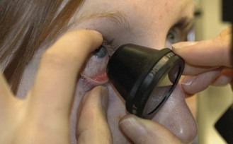
6. Lens insertion: Move the microscope off to the side or reach around the microscope to insert the lens. Advise the patient that pressure and a turning feeling may be detected with the lens in place, but that there will be no discomfort. Instruct the patient to look up. Eyelid control is usually required to ensure the lens is properly inserted in one attempt. One method is to hold the eyelashes of the upper eyelids tightly against the orbital rim with the thumb, then pull the lower eyelid down and away from the globe and introduce the rim of the lens over the lower eyelid margin. Use the lens edge to pull down the lower eyelid further, while simultaneously and quickly rotating the lens upwards onto the eye (Figure 7.23). Once the lens is on the eye, ask the patient to slowly look straight ahead. Keep the flat front surface perpendicular to the line of sight. If air bubbles are present, apply a little pressure and gently rock the lens to see if they can be removed. The angle can often be viewed around air bubbles, but if they remain a significant problem with the view, remove and re-insert the lens. Consider manipulating the lens through a couple of rotations with both hands to establish the lens seal and enable smooth rotation of the lens while observing the various angle quadrants. Wipe excess solution that may have dripped onto the patient’s cheek.
7. Examination/observation procedure: For examination, it is preferable to hold the lens with the left hand when examining the right eye and vice versa for the left eye. Either two hands can be used to rotate the lens to view all four quadrants, or one hand can be used with stabilisation of the lens between rotations with the middle finger.
8. Start with a vertical parallelepiped beam 1–3 mm wide. Keep the illumination moderate to reduce pupillary constriction that may decrease the perceived width of the angle and prevent patient discomfort.
9. Start with the thumbnail mirror placed in the 12 o’clock position to enable a view of the inferior angle first. The inferior quadrant is usually the widest and most pigmented, making it easier to identify the various structures.
10. In normal angles, look for the prominently discernible pigmented posterior structure, the ciliary body (CB) band, and identify the adjacent angle structures from posterior through to anterior (Figure 7.24). Identify the most posterior structure observable and note any abnormal findings.
Fig. 7.24 A wide-open angle of a brown iris (Asian). There is pigment on Schwalbe’s line (Sampaolesi’s line); iris processes overlying the ciliary body, mild pigment in the posterior trabecular meshwork and the reddish tinge is blood reflux through Schlemm’s canal.
11. When the ciliary body band is less visible or is not visible at all, such as with a narrow angle, with unusual pigment patterns or when peripheral anterior synechiae or neovascularisation obscure or distort the angle, use the focal line technique to identify Schwalbe’s line, which is the last (most anterior) structure visible in a progressively narrow angle. Use a very bright optic section at a 20° angle with the mirror in the 12 o’clock position. Two separate beams representing the anterior and posterior surfaces of the cornea will be observed in the domed cornea above the angle. These two beams will collapse into one beam in the angle at Schwalbe’s line. All other structures can be identified posteriorly from Schwalbe’s line. This technique can also be used with the thumbnail mirror in the 6 o’clock position (superior angle examination), but it is usually not necessary if you follow the structural variations through the examination of all 360° of the angle.
12. The convex iris technique can be used to help identify the most posterior angle structure observable before the iris inserts into the angle.
13. Use both hands and rotate the lens by 90° to observe the nasal or temporal angle. Use one hand to hold the lens to maintain contact with the eye and use the other hand to rotate the lens. The lateral angles may be more easily viewed when the slit beam is rotated horizontally.
14. Examine all quadrants (through 360°) in a systematic manner.
15. Lens removal: Instruct the patient to look toward the nose and blink forcefully (the strongest eyelid force is nasally), while simultaneously applying digital pressure through the inferior eyelid on the temporal side of the globe to introduce air beneath the lens. A popping sound may be heard as the lens releases from the eye. Repeat with more pressure temporally if the first attempt fails to release the lens. Do not use a pulling force to remove the lens. Consider lavage of the superior and inferior cul-de-sacs with irrigating solution (or saline) if viscous, preserved coupling solution was used.
16. Always examine both eyes as relative comparison of angle structures between eyes and quadrants is important.
7.6.4 Corneal-type gonioscopy procedure
1. Describe the specific indications for gonioscopic assessment to the patient and outline the procedure; for example, ‘I would like to use a contact lens on the front of your eye to examine the structures which drain the fluid of the eye. I will be putting a drop in your eyes to numb the cornea, so do not rub your eyes for at least half an hour or you could scratch your eye without feeling it.’
2. Lens preparation: Clean and disinfect the gonioscopy lens. No solution is absolutely required; however, a drop of solution may improve the contact and facilitate maintenance of the contact and therefore the view. A drop of saline, artificial tear or viscous solution may be used.
3. Anaesthetise both eyes. Gonioscopy can be performed immediately following applanation tonometry so that additional anaesthetic is not necessarily required. Fluorescein does not interfere with the examination.
4. Position the patient comfortably at the biomicroscope and ensure the patient is aligned properly with the lateral canthal marker so that the chin rest need not be adjusted while the lens is on the eye.
5. Align the illumination system to be co-axial with the viewing system, set the magnification to a low power (e.g. 10×), and the rheostat to low or medium intensity. Pull the biomicroscope back toward you.
6. Lens insertion. Before applying the lens, consider the orientation of the mirrors, especially with lenses with handles (Zeiss – Unger holder, Posner – one piece). Generally, the lens is applied with the handle superior- or inferior-temporally in a ‘square’ pattern (Figure 7.22b), although a ‘diamond’ pattern is preferred by some clinicians. Advise the patient that the lens will be felt if the lids touch it but otherwise will not be uncomfortable.
7. It is preferable to hold the lens with the left hand when examining the right eye and vice versa for the left eye. Lens stability is critical so it is important to have good arm support.
8. Instruct the patient to hold their eyes widely and to look straight ahead (a specific target to fixate on is helpful). Pull the microscope back, and bring the lens in from the patient’s temporal side. Rotate the lens quickly and directly onto the central cornea so that the flat front surface is perpendicular to the line of sight. At all times, hold the lens just barely in contact with the corneal surface such that the tear prism is maintained. Do not apply excessive pressure with the lens. A wrinkled appearance through the lens indicates that folds in Descemet’s membrane are occurring due to too much pressure on the lens. Maintain the flat lens perpendicular to the cornea to maintain the tear film seal, and reposition the lens on the centre of the cornea if sliding is noted or if the patient changes fixation.
9. Position the vertical slit beam in the mirror placed in the 12 o’clock position to enable a view of the inferior angle first. The inferior quadrant is usually the widest and most pigmented, making it easier to identify the various structures.
10. In normal angles, look for the prominently discernible pigmented posterior structure, the ciliary body (CB) band, and identify the adjacent angle structures from posterior through to anterior. Identify the most posterior structure observable and note any abnormal findings.
11. When the ciliary body band is less visible or is not visible at all, such as with a narrow angle, with unusual pigment patterns or when peripheral anterior synechiae or neovascularisation obscure or distort the angle, use the focal line technique to identify Schwalbe’s line, which is the last (most anterior) structure visible in a progressively narrow angle. Use a very bright optic section at a 20° angle with the mirror in the 12 o’clock position. Two separate beams representing the anterior and posterior surfaces of the cornea will be observed in the domed cornea above the angle. These two beams will collapse into one beam in the angle at Schwalbe’s line.
12. The convex iris technique can be used to identify the most posterior angle structure observable before the iris inserts into the angle and pressure gonioscopy can be used in narrow angles to ensure there are no peripheral anterior synechiae, and to differentiate appositional and synechial angle closure.
13. Rotate the slit beam horizontally and position the beam in the appropriate mirror to observe the nasal or temporal angle.
14. Examine all quadrants (through 360°) in a systematic manner.
15. Lens removal: Remove the lens by simply releasing from contact with the cornea. No ocular lavage is required as no preserved coupling solution is used. Examine the cornea after the procedure to ensure the epithelium is intact.
16. Always examine both eyes as relative comparison of angle structures between eyes and quadrants is important.
7.6.6 Recording
• Most posterior angle structure observed (e.g. posterior trabecular meshwork).
• Angular approach at the recess (approximation, in degrees).
• Iris contour (e.g. ‘flat’, ‘steep’ or ‘convex’ in mid-peripheral iris as in narrow angles; ‘convex at iris root’ as in plateau iris; ‘convex over entire iris’ as in pupillary block; or ‘concave’ or ‘posteriorly bowed’ as in pigment dispersion).
Other characteristics and pertinent negatives include:
• Presence of iris processes, angle recession, peripheral anterior synechiae (PAS), and normal and abnormal vasculature.
• Other findings: lens cortex material, naevi and surgical alterations such as sclerectomy and peripheral iridotomy (PI).
• Whether or not lens tilt (convex iris technique) was required to observe the angle properly.
• To what degree the angle opens with indentation (if relevant).
7.6.7 Interpretation
Trabecular meshwork (TM)
The trabecular meshwork or trabeculum has a translucent appearance and is frequently dull grey or brown in appearance. The anterior portion of the trabecular meshwork (ATM) is usually less pigmented and is considered the non-filtering portion of the meshwork. The more posterior portion of the trabecular meshwork (PTM) overlies the Schlemm’s canal and is more active in the drainage process. The PTM is pigmented and may accumulate pigment with age and in specific eye disease such as pigment dispersion and pseudoexfoliation syndromes. Trauma, uveitis and surgery are also causes of pigment deposition in the angle. It is advisable to grade the level of pigmentation in the angle, and it is usually noted that pigment deposits most heavily in the inferior quadrant. Schlemm’s canal can be seen through the translucent meshwork only if blood is refluxed back into it from the venous system (Figure 7.24). This occurs if excess pressure is applied with the gonioscope (usually a scleral-type lens), such that the pressure in the draining veins exceeds the intraocular pressure.
7.6.8 Other gonioscopic findings
Neovascular growth may be preceded by rubeosis iridis at the pupillary ruff; however, neovascularisation of the angle may occur without neovascularisation of the iris. Early neovascular bridging vessels across the angle can be very difficult to detect. The risk of missing neovascularisation by not performing gonioscopy in patients with central retinal vein occlusion is about 10%.30
7.6.9 Most common errors
1. Misinterpreting angle structures. A narrow angle is the most difficult to interpret.
2. Using the wrong amount of solution with scleral-type lenses: too little solution can cause bubbles behind the lens limiting the view of the angle, while too much can cause the excess solution to run onto the patient’s cheek.
3. Using too much pressure with a corneal type lens, which indents the cornea, causing folds in Descemet’s membrane as well as falsely widening the angle.
7.7 Tonometry
Although tonometry is now known to be a poor screening test for glaucoma compared to optic nerve head and visual field assessment, it identifies ocular hypertensive patients who should subsequently be monitored more closely and provides essential additional information when used in conjunction with the other assessments.31 In addition, intra-ocular pressure (IOP) measurement is critical in monitoring glaucoma treatment as reducing IOP is currently the only effective approach to slow down glaucoma progression.32 Tonometry must be performed in any patient with glaucoma or ‘at risk’ of glaucoma, e.g. suspicious discs, family history of glaucoma, central visual field defect, narrow anterior angles, etc.
7.7.1 Comparison of tonometers
Goldmann applanation tonometry (GAT) has long been the gold standard for IOP measurements and its accuracy is such that it is used to determine the validity of other tonometers. The Perkins tonometer uses the same principal as the GAT, but is a hand-held tonometer and does not require a slit-lamp biomicroscope (Figure 7.25). Its advantages are that it is portable, can be used on domiciliary (home) visits and being hand-held may be used with the patient either sitting up or lying down (note that the IOP will likely be higher when the patient is lying down). In addition, some patients are less apprehensive with this technique. Its disadvantages include that it is less stable than the biomicroscope-mounted instrument, has a fixed low magnification for viewing the mires and does not allow for efficiently examining the cornea before and after the test as the patient is not already at the biomicroscope.
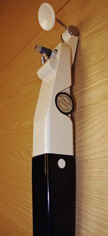
Both GAT and Perkins have the disadvantage that they only provide valid measurements for corneas with near average thickness. For a very thick corneas, GAT tends to overestimate IOP, and for very thin corneas it underestimates IOP. For example, Johnson et al. reported details of a 17-year old patient with GAT readings between 30 and 40 mmHg due to extremely thick corneas of 0.90 mm (compared to a normal average of 0.54 mm) whose ‘real’ IOP was 11 mmHg.33,34 This inaccuracy of GAT has been known for some time, but has come to the fore since the findings of significant IOP reductions due to the corneal thinning induced for refractive surgery.34,35 The influence of central corneal thickness on applanation IOP may lead to the classification of some normal subjects with thick corneas as ocular hypertensives and several reports have suggested that central corneal thickness should be measured in ocular hypertensives,33,34,36 making the measurement of central corneal thickness the standard of care in the assessment of those at risk of glaucoma. Some reports have suggested that non-contact tonometry provides even higher IOP values than Goldmann tonometry in patients with thick corneas.37,38 In addition, this effect could also mean that some patients diagnosed as having normal tension glaucoma using GAT may actually be patients with high IOP but a thin cornea.39 In this regard, a clinical note reports two cases of post-LASIK patients with steroid response progressing to end-stage glaucoma, and that the late detection may have been partly caused by unreliably low IOP after surgery.40 Attempts have been made to determine the relationship between corneal thickness and GAT to provide a validated correction factor, but there is wide disagreement among investigators.41
Of the non-Goldmann tonometers, a systematic review of the literature suggested that the NCT seems the most accurate, with two-thirds of readings within 2 mmHg of GAT.42 Most non-contact tonometers (NCTs) are now highly automated and simply involve lining up the instrument in the correct position when it will automatically take measurements. They are easier to perform than Goldmann or Perkins tonometry, do not require corneal anaesthesia, and can be performed by trained clinical assistants. However, results are typically less reliable than GAT with slight differences that are model dependent.42 You should check the literature for information regarding the model type you have. At least three readings are required to average the effects of the arterial pulse, which varies IOP by over 4 mmHg. However, averaging four measurements appears to provide the best sensitivity and specificity of results and is recommended.43 If an NCT is used, a useful protocol can be to screen patients who do not have risk factors for glaucoma using NCT measurements taken by a clinical assistant and to repeat any measurements which are high, unequal or increased from previous visits using GAT or Perkins. Any patient with glaucoma or any risk factors for glaucoma should have pressures measured by contact tonometry.
7.7.2 Procedure for GAT

1. Make certain that the tonometer probe tip has been appropriately disinfected. Check the integrity of the cornea for any contraindications to performing the technique.
2. Explain the test to the patient and obtain informed consent. Ask about any sensitivity to the anaesthetic. For example: ‘I am now going to measure the pressure in your eye, which is one of the tests for glaucoma. This involves putting a drop in your eye. Have you ever reacted badly to drops or an anaesthetic before at an optometrist’s or dentist’s office?’
3. Inform the patient that the drops will sting at first but that the stinging will disappear very quickly. Instil one drop of anaesthetic or anaesthetic/fluorescein solution in both of the patient’s eyes (section 7.8). You may suggest that the patient closes their eyes as this can be more comfortable. Keep a tissue handy to dab the patient’s tears subsequently. Allow approximately 30 seconds for the anaesthetic to take effect.
4. Position the patient comfortably at the slit lamp, with their lateral canthus aligned with the marker on the head rest and with the patient’s chin in the chinrest and forehead against the headrest.
5. If required, add a small amount of fluorescein to both conjunctivae. Fluorets can be wet with preserved saline or another drop of the anaesthetic, although the pH of the anaesthetic will reduce the fluorescence of fluorescein. Insufficient fluorescein will result in poorly visible mires.
6. With the fluorescein in place, check for corneal staining prior to performing tonometry. Ensure there are no conditions that would contraindicate applanation tonometry, such as a serious corneal injury (this is likely to have been identified in the case history).
7. Insert the tonometer probe into the Goldmann tonometer and align the white line on the carrier with the 0°/180° degree line on the probe. Astigmatic corneas produce an error of 1 mmHg for every 4 D of corneal cylinder. To reduce this error, adjust the tonometer head to 43° from the flattest corneal meridian if the corneal cylinder is greater than 3 D. If astigmatism is with-the-rule or against-the-rule, the probe can be aligned with the red line on the probe carrier (at 43°).
8. Goldmann tonometry is a monocular technique. Position the Goldmann probe in front of the slit-lamp eyepiece that corresponds to your dominant eye. For example, if you are right eye dominant, insert the tonometer body into the right hand hole on the slit-lamp tonometer plate, so that you will view the probe image through the right eyepiece.
9. Set the tonometer scale to an average setting of about 16 mmHg (1.6 g on the GAT scale), so that minimal movement of the tonometer scale is subsequently required. Use low (~10×) to moderate (~16×) magnification, turn the illumination system to 45° to 60° to the temporal side of patient, and adjust the system to the widest beam and the cobalt blue filter. You may need to increase the slit-lamp illumination.
10. Adjust the biomicroscope to align the probe with the centre of the patient’s cornea.
11. Encourage the patient to blink a few times, then to stare straight ahead.
12. Bring the probe towards the cornea. Corneal contact is signalled by either a green glow on the peripheral cornea when you are looking outside the instrument or by the appearance of two green arcs when you are looking into the eyepiece.
13. At first contact, two green hemispherical pools of fluorescein may be seen. These are caused by the tears filling in the gap between the cornea and the tonometer probe. If these are seen, move the probe very slightly further forward to applanate the cornea. The probe and its arm will then be seen to move backwards.
14. Determine whether you have the correct amount of fluorescein by assessing the diameter of the green arcs. Their thickness should be about one-tenth the size of the diameter of the arcs (Figure 7.26). If the arcs are too thin, there is insufficient fluorescein and more should be instilled. If the arcs are too thick, a tear meniscus has formed around the outside of the probe and you should attempt to remove excess tears from the eye and probe using a tissue. This is a common problem in patients with a large tear volume.
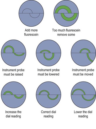
15. If the arcs can both be seen, but are not correctly positioned (Figure 7.26), move the probe while still in contact with the cornea until the two green arcs are of equal size above and below the horizontal line of the probe beam splitter and are centred in your view (Figure 7.26). Always move the probe towards the larger ring. If only one (or neither) arc can be seen, remove the tonometer tip from corneal contact to make small adjustments to the position of the tonometer probe until both arcs can be seen.
16. Some clinicians gently hold the superior eyelid with the forefinger and lower lid with the thumb to ensure the eyelids do not touch the probe. Do not put pressure on the patient’s globe as this will artificially increase the IOP.
17. Adjust the tonometer scale until the inner edges of the green arcs are just touching, then remove the probe from the patient’s eye. If a pulsation is perceived, adjust the scale such that the pulse centres on the correct alignment pattern.
18. Take the tonometry reading. The dial is calibrated in grams, with each gram being equivalent to 10 mmHg, so that a reading of 1.6 grams indicates an IOP of 16 mmHg.
19. Examine the cornea for unintentional damage. Examine the depth of any abrasion using an optical section technique. Deep and/or extensive abrasions made by novices may need analgesic or other treatment and should be monitored.
20. Inform the patient not to rub their eyes and to avoid dusty or windy environments for at least half an hour because of the anaesthetised cornea. Contact lens wearers must be warned to not wear their contact lenses for at least the same time period.
7.7.3 Alternative procedure: Perkins tonometry
1. The procedure is the same as that with GAT, except for the setting up of the instrument:
2. Adjust the chair so that the patient is slightly below your eye level.
3. Instruct the patient to look at the duochrome or other target that fixes the eyes in a slightly elevated position looking towards the instrument.
4. Rest the instrument on the patient’s forehead and pivot the instrument so that the probe can make contact with the centre of the cornea.
5. Hold the patient’s eyelids apart if needed, taking care not to press on the globe.
6. The remainder of the procedure is the same as for Goldmann tonometry. Contact time must be kept to a minimum as there is a greater possibility of abrasion with Perkins compared to GAT.
7.7.5 Interpretation
The range of normal Goldmann IOPs is from 7 to 20 mmHg (mean of about 13 mmHg). However, note that Goldmann readings are influenced by central corneal thickness and provide a significant underestimation with corneal epithelial oedema.34,44 Various systemic drugs can alter IOP, including systemic and topical steroid use that can significantly raise IOP in steroid ‘responders’ and beta-adrenergic blockers that can lower IOP. IOPs below 7 mmHg may suggest conditions such as retinal detachment, uveitis or wound leak. IOPs above 20 mmHg indicate ocular hypertension and may suggest glaucoma. However, note that patients can have primary open-angle glaucoma and have a normal IOP below 21 mmHg. The difference in IOP between the two eyes should not exceed 4 mmHg. IOPs vary diurnally, with the highest IOP generally measured in the mornings. If a suspected glaucoma patient has a normal IOP in the afternoon, ask the patient to return on another day in the early morning, so that IOPs can be remeasured at that time.
7.7.6 Most common errors
1. Obtaining high IOPs because of patient apprehension. Describing the procedure to the patient in non-threatening terms can help.
2. Taking a reading when a tear meniscus has formed around the GAT probe leading to two thick tonometer arcs and an invalid, low pressure measurement.
3. Not explaining the NCT procedure and demonstrating it to the patient, so that he or she is unnecessarily startled.
7.8 Instillation of diagnostic drugs
7.8.1 What are the risks with diagnostic drugs?
Diagnostic drugs are available to the majority of optometrists and other primary eye care practitioners throughout the world. The three major types of diagnostic drugs available are anaesthetics, cycloplegics and mydriatics. Staining agents are discussed in section 7.3. The advantages to be gained by using these drugs far outweigh the possible adverse ocular and systemic effects that rarely occur. For example, in a systematic review of published research between 1933–1999, Pandit and Taylor concluded that the risk of inducing acute glaucoma following mydriasis with tropicamide alone is close to zero, and the risk with long-acting or combined agents is between 1 in 3380 and 1 in 20,000.27 Mydriasis with tropicamide alone is safe even in patients with primary open angle glaucoma. Note that the most common cause of malpractice claims in the US is misdiagnosis of intraocular disease, principally retinal detachment, open-angle glaucoma, and tumours. The great majority of claims alleging misdiagnosis involve optometrists who have failed to use diagnostic drugs for dilation of the pupil with very few claims being due to adverse responses to ophthalmic drugs.45 Of course, precautions must always be taken when using any of these drugs to ensure that the patient is at minimal risk.
7.8.2 Obtaining informed consent
1. Using lay terms, inform the patient about the technique you wish to use and the rationale for doing so.
2. Inform the patient whether the drops will sting, how long any side effects (e.g., near blur and photosensitivity with mydriatics) will last and the chances of an adverse reaction.
3. If you wish to use a mydriatic or cycloplegic, ask the patient whether they are going to operate heavy machinery or drive or perform a similar activity requiring good vision following the eye examination. Ideally patients should be informed not to drive after the examination if possible and if pupillary dilation is likely, it is good practice to advise patients to bring a driver with them or use alternative transport to the practice. Indeed, if pupillary dilation is routine, this advice can be provided to patients when they make the appointment and printed on their appointment card. If driving is their only option for transport home, allow sufficient time for them to adapt to a dilated pupillary state and recommend that they drive only on familiar roads. Commercially available paper sunglasses or attachments could be provided if it is sunny. If the patient has to operate heavy machinery or perform a similar possibly dangerous task, make another appointment for them when they can have their pupils dilated.
7.8.3 Safety checks
1. Case history/case history notes. If the following information is not included in your initial case history notes, make sure you ask about them prior to instillation of the drops.
(a) Does the patient report symptoms suggestive of angle closure?
(b) Does the patient have any systemic or ocular disease that could be aggravated by the use of a diagnostic drug? For example, patients with angle closure glaucoma, with or without surgical or laser treatment, should be dilated with caution.
(c) Does the patient have a systemic condition that could be aggravated by the instillation of a diagnostic drug? For example, one case highlighted the need to avoid hyper extending the neck of a child with Down’s syndrome when instilling drops to prevent spinal cord injury.46
(d) Has the patient been given similar drops before and did they have a reaction to them?
2. Visual acuity. Make sure that you record distance visual acuity before any procedure is carried out on the patient. If you have not already measured visual acuity, make sure that it is measured prior to instillation of the drops.
3. Anterior angle assessment. You should estimate the size of the anterior chamber angle before using any drug that has mydriatic effects (section 7.5). Do not use miotics after mydriasis as it is generally unnecessary and pilocarpine can even cause angle closure by producing a mid-dilated pupil.27,47 As indicated previously, the risk of inducing acute angle glaucoma using a mydriatic is very low. Indeed, some clinicians take the view that it is better for patients to have a mydriatic-induced angle closure in their office/practice, where appropriate treatment can be provided, than in the patient’s home. In situations where you dilate a pupil of a patient ‘at risk’ of angle closure, make sure that you obtain informed consent, and be prepared to manage any subsequent angle closure.48 Angle closure is even less likely to occur with mydriasis due to a cycloplegic, as cycloplegia is generally used on a much younger population than mydriatics.
4. Slit-lamp examination. Prior to mydriatic instillation, check for contraindications such as synechiae, subluxated crystalline lens, dislocated intraocular lens implant, exfoliation or pigmentary glaucoma. If any of these conditions are found, avoid mydriasis if possible or proceed with great caution. Determine the integrity of the cornea before any drops are instilled and after any procedure involving the cornea, such as contact tonometry or gonioscopy.
5. Tonometry. Assess IOP prior to the instillation of mydriatics/cylcoplegics. Some exceptions include when cyclopleging infants and very young children for refractive error assessment.
7.8.4 Choosing the appropriate drug and dosage
1. Case history/case history notes. If the following information is not included in your initial case history notes, make sure you ask about them to help you choose the appropriate drug and dosage.
(a) Does the patient have any systemic or ocular disease that could be aggravated by the use of a diagnostic drug? For example, phenylephrine 10% should not be used in those patients with severe cardiac disease, systemic hypertension and hypotension, insulin-dependent diabetes, aneurysms or advanced arteriosclerosis. Phenylephrine 2.5% should only be used with great caution in these patients. There have also been reports of similar problems after the use of hydroxyamphetamine hydrochloride 0.25% used in combination with tropicamide 0.25%.49
(b) Does the patient have any systemic or ocular disease that could have an influence on the choice of a diagnostic drug? For example, it is often difficult to obtain satisfactory mydriasis in patients with diabetes and they may require additional mydriatic drops and/or a combination of mydriatic drops (tropicamide 0.5% or 1% plus phenylephrine 2.5%). Patients with kidney disease can have unusually slow detoxification and elimination of ocular diagnostic drugs systemically absorbed and care should be given to use the lowest necessary dosage of the drug. Conversely, note that patients with a compromised corneal epithelium can have enhanced penetration of a diagnostic drug.
(c) Is the patient taking systemic medication that could interact with a diagnostic drug? For example, phenylephrine should not be used if the patient is taking monoamine oxidase inhibitors or tricyclic antidepressants.
(d) There is a general lack of information on the use of specific drugs in women who are pregnant or breastfeeding. However, diagnostic drugs, including topical ophthalmic dyes, anaesthetics and mydriatics, are generally considered safe as long as standard cautions, warnings and contraindications are considered.
(e) Has the patient had an allergic reaction to eye drops previously?
2. Iris colour. In general, patients with lighter irides will respond quicker and to a greater degree than those patients with dark irides. Therefore, give a higher drug dosage to a patient with dark irides and/or use a combination drug approach.
3. The drug(s) and dosage (concentration and number of drops) will depend on the procedure you are going to perform. Some clinicians choose to use a combination drug routinely and other clinicians use this approach when greater dilation is required, such as when using head-band binocular indirect ophthalmoscopy. This is achieved either with a drop of two drugs, such as one drop of phenylephrine 2.5% and one drop of tropicamide 0.5% (or 1%) or the use of a combination drop which contains both of these agents (e.g., tropicamide 0.8% and phenylephrine 5%).
4. Instilling a topical ocular anaesthetic prior to the use of a mydriatic or cycloplegic agent (one may have been used for contact tonometry) results in an enhanced mydriatic/cycloplegic effect. The anaesthetic, as well as reducing possible discomfort, can reduce lacrimation and thus reduce drug washout for subsequently instilled drugs. It has also been suggested that the mildly toxic effects of a topical anaesthetic on the cornea opens up the intracellular spaces and aids penetration of other drugs.
5. In all cases, choose the drug with the least possible adverse effects and the lowest concentration that will allow you to efficiently attain the cycloplegia or mydriasis that you require. For example, research has suggested that cyclopentolate 1% is sufficient to produce good cycloplegia, with an effect similar to atropine 1%, in patients with accommodative esotropia and that tropicamide 1% is as effective as cyclopentolate 1% for the measurement of refractive error in most healthy, non-strabismic infants.50,51
7.8.5 Checks prior to instillation
1. Ensure that you have performed all the procedures prior to instillation of the diagnostic drug that would not be possible after it has been instilled. For example, make sure that you assess pupil reflexes, near muscle balance and accommodation prior to using a cycloplegic and tonometry prior to a mydriatic.
2. Carefully identify any drops before instillation by checking the brand name, ingredients, and expiration date and checking for discoloration and precipitates. If the expiration date has passed, or if there are precipitates, discoloration or other signs of contamination, the suspect container should be discarded and a new one obtained.
3. Before the instillation, record the drug type (preferably by its brand name) and dosage (concentration and number of drops used in each eye). The use of the brand name is useful since it uniquely identifies the particular preparation that has been used. Different brands may well have different preservatives or other non-active ingredients.
4. Recheck the container of the diagnostic drug for its identity and remove the cap in preparation for drug instillation. If a dropper bottle is being used, do not place the dropper cap on any surface in such a way as to risk contaminating the inside of the bottle cap. It is best if you hold it in your hand.
7.8.6 Drug instillation procedure

1. The patient should be seated in a fixed chair with a proper back support and arm rests. There is a chance that upon instillation, the patient (especially a child) will abruptly move. Therefore do not use a stool or a chair on casters.
2. Ask the patient to tilt their head backwards with the chin raised slightly.
3. Gently pull down the lower eyelid or pull it forward slightly to form a pouch.
4. Instil a drop or drops into the temporal side of the pouch. Avoid touching the eyelashes, eyelids or conjunctiva with the dropper tip. Gently release the lower eyelid.
5. In the case of ointment, gently squeeze a 1.5 cm ribbon of ointment inside the lower fornix.
6. Ask the patient to look downward and gently release the upper eyelid over the eye.
7. Press firmly over the lacrimal sac (just medial to the inner canthus) for at least ten seconds. Nasolacrimal occlusion prevents any excess drug entering the nasolacrimal duct, keeping systemic absorption to a minimum. Nasolacrimal occlusion is not required when an ointment is used. Make sure that you wipe any excess drops/ointment away from the eye with a tissue.
8. If two drops are to be used, wait at least three minutes between drops. Instilling two drops consecutively without this wait overfills the lacrimal lake and negates the theoretical effect of applying more drug.
7.8.7 Post drug instillation procedure
1. Return the cap to the bottle (and screw on securely) or dispose of single dose products such as Minims.
2. Anaesthetics: Inform the patient not to rub their eyes and avoid dusty or windy environments for at least half an hour after use of an anaesthetic. Contact lens wearers must be warned to not wear their contact lenses for at least the same time period.
3. Mydriasis: Measure intra-ocular pressure post-mydriasis for patients at risk of angle closure. A rise of more than 5 mmHg should be monitored until it returns to normal levels.
4. Provide commercially available paper sunglasses or attachments after mydriasis when necessary to avoid photophobia.
5. Use appropriate follow-up procedures and/or emergency care should any untoward reactions or sequelae occur. All these drugs (with the exception of tropicamide, for which no serious adverse effects have been recorded) can give rise to systemic effects such as altered mental states and increased heart rates. Patients may also faint. Note that an unwanted reaction such as a rise in IOP due to pupil block post-mydriasis can develop some hours later, and ‘at risk’ patients should be told who to contact in case of an emergency.
7.8.8 Recording
Record the time, the number of drops instilled into each eye and the drug and its concentration.
7.9 Pupil light reflexes
7.9.1 Pupillary function
Evaluation of pupillary function provides valuable information about the integrity and function of the iris, optic nerve, posterior visual pathways and the third and sympathetic nerves to the eye, and some of the conditions that cause pupil reflex abnormalities are life threatening. Afferent pupillary defects are caused by lesions in the ‘front end’ of the pupillary light reflex pathway and most commonly by lesions in the retina and optic nerve. The afferent pupillary pathways leave the visual pathways in the last third of the optic tracts to reach the pretectal nuclei (Figure 7.27). Afferent pupillary defects do not cause anisocoria (different pupil sizes), but may produce abnormal pupillary light reflexes. Efferent pupillary defects produce anisocoria and are caused by lesions to the motor neurone system, which carries signals from the central nervous system to the iris via the 3rd cranial nerve.
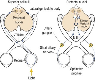
7.9.2 Comparison of tests
Pupil size should be assessed in both bright and dim illumination to investigate any anisocoria. The swinging flashlight test provides a sensitive assessment of any unilateral or asymmetric afferent defects, and has been shown to be superior to the Marcus Gunn test (redilation under sustained illumination) for detecting relative afferent pupillary defects.52,53 There is no condition in which the near reflex is defective or lost when the light reflex is normal. Therefore the near reflex need only be checked if the light reflex is abnormal. Patients can show an abnormal light and near pupil reflex or an abnormal light reflex with a normal near reflex (light-near dissociation).
7.9.3 Procedure for pupil assessment

1. Ask the patient to take off their glasses, and look at a letter on the distance visual acuity chart that both eyes can see easily. If the worst monocular visual acuity is less than about 6/18 (20/60) ask the patient to look at a spot of light on the distance chart.
2. Sit in front and to the side of the patient, so that you can easily observe the patient’s pupils, but you are not obscuring fixation of the target.
3. Keep the room lights on and check the size, shape and location of both pupils. Compare the size of both pupils carefully. You can estimate the size of the pupil using the iris as an approximate 12 mm reference scale (Figure 7.28).
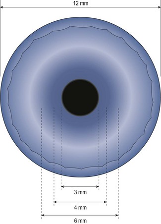
4. If the pupil sizes are unequal in bright light conditions, measure the pupil sizes with a millimetre ruler or a hemisphere scale. In addition, dim the room lights but keep the light levels high enough so that you can clearly see the patient’s pupils, and measure the size of the patient’s pupils again. An ultraviolet lamp, such as a Burton lamp used for contact lens fitting, can be used with patients with dark irides as the lens fluoresces to allow pupil sizes to be measured.
5. Direct and consensual light reflexes:
(a) Ask the patient to remain fixating a letter or spotlight on the distance chart.
(b) Shine a penlight or direct ophthalmoscope into the right pupil from the inferior temporal side from a distance of 5 to 10 cm. Observe the extent and speed of constriction of the right pupil (direct light reflex) and left pupil (consensual reflex). Remove the light and observe the direct and consensual dilation. Check this several times as dramatic fatigue can occur in an abnormal eye that at first shows a normal response.
(c) Shine the light into the left pupil from the inferior temporal side from a distance of 5 to 10 cm. Observe the extent and speed of constriction of the left pupil (direct light reflex) and right pupil (consensual reflex). Remove the light and observe the direct and consensual dilation. Check this several times.
(a) Ask the patient to remain fixating a letter or spotlight on the distance chart.
(b) Shine a penlight or direct ophthalmoscope into the right eye from below the patient’s eyes from a distance of 5 to 10 cm. Pause for 2–3 sec and then quickly switch the light to shine into the left eye.
(c) Repeatedly alternate between the two eyes, pausing for 2–3 sec on each eye, and look for any change in pupil size as the light is alternated.
(d) A normal response is that both pupils will constrict as the penlight is shone in one eye. As the light is moved off the eye on its way to the fellow eye, both pupils will dilate. As the light reaches the fellow eye, both pupils constrict. After the light has been shone on a pupil for 1–2 seconds, the pupils may redilate slightly, so it is important to observe the pupils at the instant the light first falls on them.
(e) An eye with a relative afferent pupillary defect (RAPD) will dilate as the eye is first turned upon it, as the consensual dilation response due to the light moving off the good eye overpowers the poor constriction response from the affected eye.
(f) The RAPD can be quantified by adding successively increasing neutral density filters to the ‘good’ eye, until a normal swinging flashlight response is seen.
7. Near reflex: This need only be measured if the light responses are abnormal or sluggish.
(a) Ask the patient to remain fixating a letter or spotlight on the distance chart.
(b) Ask the patient to then look at a target such as the patient’s own thumb about 15 cm from his or her eyes.
(c) Observe the extent and speed of pupillary constriction as the patient changes fixation from distance to near.
(d) Ask the patient to look back at the distance target and observe the dilation as this occurs.
7.9.5 Interpretation
An abnormal direct light response in a pupil capable of a normal consensual response indicates an afferent (visual pathway) defect. There is generally no anisocoria. The swinging flashlight provides a more sensitive assessment of any unilateral or asymmetric afferent defects. It compares each eye’s direct response (reflecting the normality of its visual pathway) with its consensual response (reflecting the normality of the other eye’s visual pathway). Symmetrical afferent defects do not show a positive RAPD. Some normal subjects may show a persistent but small RAPD in the absence of detectable pathologic disease. Therefore, an isolated RAPD in the range of 0.3 log unit that is not associated with any other significant historical or clinical finding should probably be considered benign.54 Similarly, patients with unilateral cataract may show an RAPD in the non-cataractous eye that is not reflective of visual pathway disease.55
7.9.6 Most common errors
1. Using too slow a swing in the swinging flashlight test.
2. Using too low a light level to observe the contralateral eye, especially with a darkly pigmented iris.
3. Blocking the patient’s view of the visual acuity chart and stimulating accommodation and subsequent pupil constriction.
4. Forgetting to check pupil reflexes prior to instilling a mydriatic or cycloplegic.
[/level-membership-for-opthalmology-category][not-level-membership-for-opthalmology-category]7
Ocular health assessment
7.1 Differential diagnosis information from other assessments
7.2 Examination of the anterior segment and ocular adnexa
7.3 Tear film and ocular surface assessment
7.4 Assessment of the lacrimal drainage system
7.5 Anterior chamber angle depth estimation
7.8 Instillation of diagnostic drugs
7.10 Fundus examination, particularly the posterior pole
7.11 Optical coherence tomography
7.1 Differential diagnosis information from other assessments
7.1.4 Visual function
Optimal visual acuity measurements (section 3.2) that are different in the two eyes or are reduced compared to age-matched normal values or compared to a previous visit indicate some ocular abnormality. A pinhole visual acuity test can be used to make sure that the reduced visual acuity is not due to an incorrect determination of the refractive correction. Reductions in visual fields and contrast sensitivity and increases in disability glare (Chapter 3) can indicate ocular disease, even when visual acuity is normal.
7.1.5 Incomitant heterotropias
Recent-onset incomitant heterotropias can be the first sign of the underlying ocular or systemic disease including diabetes, hypertension, multiple sclerosis, thyrotoxicosis, and temporal arteritis and it is therefore essential to determine if the condition is of recent-onset or longstanding (section 6.15; Table 6.5). Missing the signs of these conditions, particularly in children, is a significant cause of malpractice claims in the US.1
7.2 Examination of the anterior segment and ocular adnexa
7.2.2 Procedure
See online video 7.1 for general slit-lamp examination. Familiarity with the adjustment controls of the slit lamp is required. The positions of the controls differ for different models but all slit lamps have similar features. It should be possible to change the width and height of the beam, rotate the beam, change the angle between the light source and viewing system, add filters over the light source (Table 7.1), change the magnification (this may involve changing the eyepieces to a stronger power), change illumination intensity, adjust the microscope height and focus the microscope with the joystick. With most instruments it is possible to break the linkage between the illumination and viewing systems (decoupling), which allows focus on a point other than that being illuminated.
Table 7.1
Filters available on most slit-lamp biomicroscopes
| Filter | Typical symbol | Use |
| Cobalt blue | Blue filled circle | Enhances the view of fluorescein dye in the tear film of the eye. Typically used for fluorescein staining and Goldmann tonometry. |
| Red free | Green filled circle | Used to enhance the view of blood vessels and haemorrhages |
| Neutral density | Circle with hashed lines | Decreases maximum brightness for photosensitive patients |
| Heat absorbing | Built into most slit lamps | Decreases patient discomfort |
| Grey | Circle with thick line | Decreases maximum brightness for photosensitive patients |
| Yellow filter | Yellow filled circle Located in the observation system |
For good contrast enhancement when using fluorescein and the cobalt blue filter |
| Diffuser | May be a flip-up filter placed on the illumination source | Used for general overall observations of the eye and adnexa |
1. Wash your hands thoroughly and clean the slit-lamp contact surfaces with a sterile wipe in front of the patient.
2. If one is available, place the focusing rod in the appropriate holder, with the flat surface towards the viewing system. Normally, you will perform the biomicroscope examination without glasses, as the field of view is greater the closer your eyes are to the slit-lamp eyepieces. If you have a high cylinder in your glasses, you may need to wear your correction to obtain adequate resolution. To focus the eyepieces, first switch on the illumination system to produce a slit-image on the focusing rod. Look through one eyepiece and turn it fully counter clockwise (plus direction) then, while viewing the focusing rod, turn the eyepiece clockwise until the slit-image on the rod is first in sharp focus. Repeat the procedure for the other eyepiece. The eyepiece should be set at approximately zero if you are an emmetrope or wearing your correction and set to your mean sphere correction (sphere + half of cylinder) if you are not wearing your glasses. More minus might be required in younger practitioners due to proximal accommodation. Once you have each eyepiece focused, adjust the distance between the eyepieces so that the image is centred in the field of view of each eye. You should see a single clear image.
3. Seat the patient comfortably on a stable chair without rollers, and ask the patient to remove any glasses. Explain the procedure in lay terms to your patient: ‘I am going to use this special microscope to carefully examine the front of your eyes.’
4. Adjust the height of the biomicroscope table so that the patient may lean forward comfortably and place their chin in the chin rest and forehead against the forehead rest. Adjust the chin rest so that the patient’s eyes are at an appropriate height to provide a large enough vertical range to allow adequate examination of the adnexa. Many biomicroscopes have an eye alignment marker on a supporting beam of the headrest that should be level with the patient’s outer canthus. If your patient is obese, an exaggerated bend at their waist will often allow satisfactory positioning. Having the patient hold onto the handles if available can also be helpful.
5. Dim the room lights and ask the patient to look at your ear (your right ear for the patient’s right eye and your left ear for the patient’s left eye) or the instrument’s fixation device so that the patient’s gaze is in the primary position.
6. Use one hand to control the joystick (focusing and lateral/vertical movement) and the other to control the magnification and illumination and to manipulate the patient’s eyelids. A useful tip is to have a low rheostat setting for a wide, diffuse beam (for patient comfort) and a high rheostat setting for a narrower beam, or when filters are used, to give sufficient image contrast.
7. There are several types of illumination that with experience you will use alternately or in combination to thoroughly examine the anterior segment and adnexa. A general procedure is to use diffuse illumination followed by a parallelepiped and is described below. This is followed by descriptions of additional techniques with examples of when they might be used.
8. Diffuse illumination: Provides an overall assessment under low magnification (~10×). Adjust the illumination to a wide beam and place a diffusing filter in front of it to systematically examine the components of the anterior segment and adnexa as described below.
9. Direct illumination using a parallelepiped: Use low to moderate magnification (~10×) as magnification that is too high will result in missing obvious, moderately sized abnormalities. Set the illumination system at approximately 45° from the microscope position on the temporal side and use a beam width of approximately 2 mm. An illuminated block of corneal tissue in the shape of a parallelogram should be visible (Figure 7.1). A beam that is too narrow will make it difficult to detect abnormalities. Assess each of the structures described below in a systematic manner using the following procedure: Focus on the temporal tissue first with the illumination coming from the temporal side. Move the slit lamp laterally across the tissue until the centre is reached, maintaining good focus at all times. Then sweep the illumination system across to the nasal side, taking care not to bump into the patient’s nose, and examine the nasal tissue. This scanning procedure may be repeated several times to examine all areas of the tissue concerned and may require more than one level of magnification. Being able to keep a parallelepiped sharply in focus as you scan from temporal limbus to central cornea and then nasal limbus to central cornea, is the foundation for good slit-lamp technique.
Fig. 7.1 (a) Diagram illustrating the position of the illuminating and viewing systems when using direct illumination. (b) A parallelepiped section of the cornea showing an irregularity above the corneal apex.
(a) Eyelids and lashes: Examine the superior eyelid and lashes first using the scanning procedure described above. This can be easier with the patient’s eyes closed. Examine the inferior lid and lashes in the same manner, while also examining lid apposition to the eye and meibomian gland appearance (section 7.3.3). Assess the lid for anomalies including an abnormal lid position (e.g., ptosis, entropion, ectropion), redness, inflammation, ulcers and growths. Inspect the lashes for colour (e.g., white), areas where the lashes are missing or misdirected and the presence of scales.
(b) Conjunctiva: Ask the patient to look upwards while you pull the lower eyelid gently downward to expose the lower fornix for examination. Examine both the bulbar and palpebral conjunctiva using a scanning process. Next ask the patient to look downwards and gently pull up the upper eyelid, thereby exposing the superior bulbar conjunctiva for examination. Finally ask the patient to look in right and then left gaze to allow examination of the entire conjunctiva, plica and the caruncle.
(c) Cornea and tear film: Use the scanning process to examine the cornea in three sweeps: inferior, central and superior. Examine the inferior cornea by having the patient look up and the superior cornea by having the patient look down while holding up the upper eyelid. With increasing experience you will be able to look at both the area illuminated (direct illumination, Figure 7.1) and the area just outside the area of illumination (indirect illumination, Figure 7.2, examples in Figures 8.12, 8.16). It can be useful to assess the tear film after a blink and note the quantity and type of debris if any. You can increase the width of the section of stroma seen by increasing the angle between the microscope and illumination system. You can obtain greater detail by increasing the magnification.
Fig. 7.2 (a) Diagram illustrating the position of the illuminating and viewing systems when using indirect illumination. (b) Corneal nerve fibres seen in indirect illumination.
(d) Assessment of the tear meniscus: The height of the tear meniscus can be estimated by decreasing the height of the slit-lamp beam to one millimetre and then judging the relative height of the meniscus at the lower lid margin as a proportion of the beam height.
(e) Iris: Examine the iris with direct illumination by moving the joystick towards the patient. Take note of the depth of the anterior chamber and the shape of the pupil.
(f) Lens: For a non-dilated pupil the illumination angle must be reduced until an optic section of the lens is just seen. This may be as small as 15° for an elderly patient with a small pupil. Further discussion of slit-lamp assessment of cataract under mydriasis is provided in section 8.4.
(g) Anterior vitreous: Moving the joystick further towards the patient allows viewing of the anterior vitreous with a parallelepiped when the pupil is dilated. To look for anterior vitreous floaters (Figure 7.3), it can be useful to ask the patient to look up, look down and then straight ahead, so that the opacities become visible as they float through the field of view (see online video 8.1).
7.2.3 ‘Specialised’ slit-lamp techniques
1 Optic section
This is a type of direct illumination in which the illumination beam is narrowed to allow a judgement of depth of any abnormalities within the cornea or lens (Figure 7.4). For example, it can be used to judge the depth of a foreign body in the cornea, whether an opacity is anterior or posterior cortical or subcapsular and is the technique used to grade nuclear lens opacity (section 8.4).
Fig. 7.4 A corneal section indicating that the corneal abrasion shown in Figure 7.1 is in the corneal epithelium.
1. Set the illumination system at approximately 45° from the microscope using low to moderate magnification (~10×).
2. If the area of the cornea/lens you wish to view is temporal, place the illumination on the temporal side and if it is nasal, place it on the nasal side.
3. Narrow the beam to the narrowest possible width and sharply focus on the cornea/lens using the joystick. As you have greatly narrowed the beam, you need to increase the slit-lamp illumination using the rheostat.
4. A slice of the cornea/lens should now be visible (cornea, Figure 7.4; lens, Figure 7.5; nuclear cataract, Figure 8.22). If the illumination system is temporal to the viewing system, the corneal epithelium or anterior lens will be on the temporal side of the image with the corneal endothelium or blurred posterior lens on the nasal side.
Fig. 7.5 An optical section of the lens anterior cortex (on the left side within the pupil) and lens nucleus (central). The posterior cortex is blurred and on the right side of the pupil. The blurred arc to the left is the out-of-focus cornea.
5. To view the posterior lens, the joystick needs to be moved further forward and the angle of the illumination system may need to be reduced further, depending on the pupil size.
6. The section of corneal stroma can be broadened by increasing the angle between the microscope and illumination system. The focusing should be precise enough to allow the graininess of the stroma to be visualised.
7. Once the object of interest is identified, increase the magnification to obtain greater detail.
2 Indirect illumination
This technique (Figure 7.6) is used to view areas that become bleached with excessive light using direct illumination, such as fine blood vessels at the limbus and microcysts. It is also used to look for iris features such as the outer rim of the iris sphincter.
1. Use a 1–2 mm parallelepiped, low to moderate magnification (~10×) and set the illumination system at ~45° from the microscope.
2. Rather than focus on the illuminated area (direct illumination), simply direct your gaze just outside the area that is illuminated (indirect illumination). Subtle abnormalities can be seen using light scattered by the cornea away from the main area of illumination.
3. Increase the magnification as required.
4. The technique can also be used after decoupling the illumination and viewing systems.
3 Specular reflection
When learning this technique, it is best to start by attempting to obtain an image of the anterior lens surface by specular reflection (Figure 7.7).
Fig. 7.7 (a) Diagram illustrating the position of the illuminating and viewing systems when using specular reflection to view the corneal endothelium. (b) Specular reflection from the anterior surface of the lens showing its orange peel appearance.
1. Set the illumination system at approximately 30° to 45° from the microscope, using a moderately wide 2–3 mm parallelepiped. Look through the eyepieces and focus the parallelepiped on the anterior lens.
2. Change the angle of illumination until the reflection of the instrument lamp is seen from the lens surface. This occurs when the angle of incidence equals the angle of reflection from the lens (Figure 7.7a).
3. View the orange peel textural appearance of the anterior lens (Figure 7.7b) to the side of the bright reflex.
4. To examine the tear film and epithelium, set the illumination system at approximately 45° to 60° from the microscope, using a moderately wide 2–3 mm parallelepiped. Look through the eyepieces and focus the parallelepiped on the cornea. Ask the patient to blink and use the particles floating in the tear film to help you focus.
5. Change the angle of illumination until a bright reflection is seen from the precorneal tear film. This occurs when the angle of incidence equals the angle of reflection from the cornea. This can also be obtained by moving the illumination/microscope system laterally until the two angles are equal.
6. To examine the endothelium, set the magnification to about 16× with a fairly wide 2–3 mm parallelepiped and initially focus on the tear film.
7. Alter the illumination angle and/or lateral position of the slit lamp until the bright corneal reflexes (Purkinje images) fall on top of the corneal section. There should be two reflexes: On the epithelial side of the corneal section there should be a bright white reflex from the tear film (conjugate with the epithelium) and on the endothelial side a less bright, slightly yellowed reflex from the endothelium. You may need to alter the angle of illumination very slightly to separate the two reflections.
8. Increase the magnification to about 40× and move the joystick slightly forward to focus on the endothelium. If you then look to the side of the dull endothelial slightly yellowed reflex (nasal or temporal to the reflex depending on the position of the illumination system) the duller picture of the endothelial hexagonal cells will be in view.
4 Eyelid eversion
1. Ask the patient to look down and grasp the superior eyelashes and pull them slightly away from the eye. It can be useful to press a cotton bud onto the superior lid to lift it away from the inferior lid, making it easier to grab just the superior lashes.
2. Gently press down on the superior margin of the tarsal plate at the crease using a cotton swab (or the index finger or thumb of the other hand), and at the same time pull the eyelashes up and over the cotton bud. This technique will evert the eyelid to permit viewing of the superior palpebral conjunctiva (Figure 7.8) using a parallelepiped.
3. To re-evert the eyelid, hold the eyelashes and ask the patient to look up and gently pull the eyelashes away from the eye.
4. To evert the lower eyelid, pull the eyelid down and press under the eyelid margin while moving your finger upwards. The eyelid will evert over your finger.
5 Retro-illumination from the iris
This technique (Figure 7.9) is used in the examination of corneal vessels, epithelial oedema, pigment deposits or keratic precipitate on the endothelium and small scars on the cornea using light reflected from the iris. Opaque features appear dark against a light background.
Fig. 7.9 Diagram illustrating the position of the illuminating and viewing systems when using retro-illumination from the iris.
1. Use a 1–2 mm parallelepiped with low magnification and set the illumination system to an angle of about 45°.
2. If it is possible to view the abnormality in direct illumination, bring it into focus and then lock the joystick position.
3. Decouple the illumination and viewing systems, direct the light onto the iris and view the structure against the light reflected from the iris. The magnification can be varied as necessary.
6 Retro-illumination from the fundus
This is a commonly used technique to examine iris disorders and cataracts using light reflected from the fundus. Cataracts are seen as dark opacities against the red background glow from the fundus (Figures 7.10, 8.20–8.24) and it is a particularly useful for examination of cortical and posterior subcapsular cataracts (section 8.4). Retro-illumination can also be used to detect iris abnormalities such as peripheral iridotomies and loss of pigment (iris transillumination, Figure 7.11). In this case, the red glow of the fundus is seen through the iris. The shape and location of the defects can help in identifying the cause of the transillumination.
Fig. 7.11 Iris transillumination. Loss of localised iris pigment is shown by the red fundal glow appearing through parts of the iris when light is shone through the pupil. (Courtesy of Dr David Williams, University of Waterloo.)
1. Use a 1–2 mm parallelepiped with low magnification and set the illumination system to an angle of 0°. Adjust the beam height to the height of the pupil.
2. Focus on the iris or lens as appropriate.
3. You will only be able to focus the anterior or posterior part of the lens at any one time. You can gain an approximate focus on the anterior lens by focusing the iris. To focus the posterior lens you will need to push the joystick forwards (towards the patient). To gain a retro-illumination image of the lens with an undilated small pupil, you may need to decouple the instrument slightly and alter the angle of illumination by a small amount.
4. Observe any illumination coming through the iris. While lens opacities are best observed with the pupil dilated, iris transillumination is best observed before dilation.
7 Sclerotic scatter
Sclerotic scatter involves observing the cornea while the illumination is directed at the limbus. The light is totally internally reflected in a healthy cornea and creates a glowing halo of light where it escapes from the opposite limbus (Figure 7.12).
Fig. 7.12 (a) Diagram illustrating the position of the illuminating and viewing systems when using the sclerotic scatter technique. (b) Sclerotic scatter showing an S-shape of contact lens deposits.
1. Turn off the room lights to keep the surrounding light levels as low as possible so you can observe subtle amounts of light scatter.
2. Set the magnification at about 10× and use a 1–2 mm slit at about 45°. Focus the central cornea by ensuring the particles in the tear film are focused. Asking the patient to blink will move the tear film debris making them easier to find. Lock the slit-lamp position to ensure the viewing system remains focused on the central cornea.
3. Decouple the illumination and viewing systems and from 45–60° on the temporal side, move the 1–2 mm slit onto the temporal limbus. Ideally, shorten the length of the slit so that it enters at the limbus. Any extra slit length can produce light scatter from the sclera that may reduce the visibility of subtle defects.
4. Although you can scan the cornea for areas of light scatter with the naked eye, it is preferable to view it using the decoupled slit-lamp viewing system. Iatrogenic damage due to novice contact tonometry or gonioscopy use, foreign bodies, scars and central corneal clouding due to rigid contact lens wear can all be observed with this technique.
8 Anterior chamber assessment
This technique is used to look for flare (i.e., protein) or floating cells in the anterior chamber (by using more magnification and a longer beam). The following procedure has been recommended by the Standardization of Uveitis Nomenclature Working Group.2
1. Turn off all the room lights and close your own eyes for a few minutes to start to dark-adapt.
2. Set the illumination system at approximately 45° from the microscope using moderate magnification (~16×).
3. Narrow the height and width of the beam to obtain a beam 1 mm by 1 mm in size. Move the beam to the centre of the pupil and focus in the anterior chamber midway between the anterior surface of the crystalline lens and the posterior surface of the cornea. Focusing forward and back within the anterior chamber will facilitate the viewing of cells.
4. Cells are a sign of active inflammation and should be counted in the grading process. Aqueous flare is the result of leakage of protein through damaged iris blood vessels and is graded by the degree of obscuration of the iris details.
9 Double eyelid eversion
1. Sterilise Desmarres Lid Retractor using an alcohol wipe.
2. Instil anaesthetic and fluorescein into the eye.
3. With the patient at the slit lamp, single-evert the upper eyelid. Use the Desmarres lid retractor to hook under the everted tarsus with the blade placed between tarsus and bulbar conjunctiva.
4. Gently pull up and out to expose the fornix.
5. Observe for any small foreign bodies using fluorescein and the cobalt blue filter on the slit lamp or irrigate the fornix in free space to try to dislodge any foreign bodies.
7.2.4 Recording
Normal appearance: If no abnormalities are detected, record ‘clear’ if the tissue is transparent, such as the cornea and lens. Otherwise record ‘No abnormalities detected’ (NAD) or ‘Within normal limits’ (WNL) or equivalent.
Anomalies/abnormalities: Record the size, shape, appearance and location of any abnormalities/anomalies using a diagram and a written description as well as digital imaging if available. In addition, observations such as fluorescein staining, corneal oedema, conjunctival anomalies (papillae, follicles), injection and vascularisation may be graded on a scale of 0 to 4+ with 0 being absence of a response, 1+ being trace response, 2+ being mild response, 3+ being moderate response and 4+ being severe response.
Cataracts: Unless digital imaging is available, record cortical and subcapsular cataracts by drawing them (Figure 7.13). The undilated pupil can be recorded as a dashed line on this diagram. If there are cortical opacities in both the anterior and posterior cortex, both should be recorded. Nuclear yellowing and opacification can be graded on a scale of 0 to 4+ with 0 being absence of opacity and 4+ being the most severe form of opacity. For more precise grading, a cataract grading system such as the LOCS III system may be used.3 In this type of system the cataract is graded on a decimal scale against standardised colour photographs.
Cells and flare: Cells in the anterior chamber are graded according to the number observed with grade 0 being <1 cell, 0.5+ being 1–5 cells, 1+ being 6–15 cells, 2+ being 16–25 cells, 3+ being 26–50 cells, and 4+ being >50 cells.2 Aqueous flare is graded from 0–4+ depending upon the visibility of the iris detail; with grade 0 being no flare, grade 1+ being faint flare, 2+ being moderate (iris and lens details remain clear), 3+ being marked (iris and lens details are hazy), and 4+ being intense (fibrous or plastic aqueous).
Contact lens complications: Contact lens complications can be graded by using the Centre for Contact Lens Research Unit (CCLRU) or the Efron grading scales (Section 5.6).4
7.2.5 Interpretation
A good understanding of the normal anatomy and physiology of the anterior segment and adnexa as well as the normal changes with age is required. Variations in normal appearance of the anterior segment and changes with age are discussed in Chapter 8.
7.2.6 Most common errors
1. Not positioning the slit lamp so that the patient is leaning forward into the chin rest. This often results in the patient not being able to maintain their forehead against the headrest, resulting in the image going in and out of focus.
2. Not focusing the eyepieces to compensate for your refractive error.
3. Not increasing the brightness when narrowing the beam or using a filter.
4. Not maintaining a sharp focus as the beam is swept across the eye.
5. Not developing a smooth, logical routine that can be repeated.
7.3 Tear film and ocular surface assessment
The tear film is usually assessed during the slit-lamp examination of the anterior segment, and is specifically indicated in those wearing or wishing to wear contact lenses (Chapter 5), patients who have undergone or wish to undergo refractive surgery and patients with any symptoms of dry eye or a history that might suggest susceptibility (e.g. patients taking medications that include beta-blockers, antihistamines, oral contraceptives and acne medications, and smokers).5 The incidence of dry eye is increased following laser refractive surgery and nearly half of contact lens wearers report symptoms of dryness.6,7 Dry eye is a multifactorial disease that results in symptoms of discomfort, visual disturbance and tear film instability with potential damage to the ocular surface and is accompanied by increased osmolarity of the tear film and inflammation of the ocular surface.8 It is classified based upon aetiology as either aqueous tear-deficient or evaporative. Aqueous deficient dry eye includes Sjögren syndrome (autoimmune) and non-Sjögren syndrome dry eye and evaporative types are classified according to intrinsic causes (e.g., meibomian gland dysfunction) and extrinsic causes (topical drug preservatives, contact lens wear and ocular surface disease such as allergy).8 Symptoms commonly include irritation, dryness, foreign body sensation, burning, gritty sensation, transient blurring of vision, stinging pain, epiphora and contact lens intolerance. Less commonly mentioned symptoms include haloes around lights (especially at night), excessive tearing, stringy mucus discharge, redness, photophobia, itching and asthenopia. Patients often report closing their eyes to obtain some relief.
The international standard criteria for dry eye diagnosis is symptom assessment, interpalpebral surface damage, tear instability and tear hyperosmolarity. Although tear hyperosmolarity is mentioned as part of the criteria for diagnosis, it is currently impractical to measure in the clinical setting.9 Assessments appropriate for primary care would include symptom recording, including by standardised questionnaire, lower tear meniscus height, tear break-up time, tear volume by Schirmer or phenol red thread test, grading of conjunctival and corneal fluorescein staining and meibomian gland expression.7
Lacrimal occlusion can also be useful for the patient with marginal dry eye who wishes to continue wearing contact lenses, as well as for short-term occlusion during the healing process after ocular surgeries such as LASIK.6,10 Patients must be evaluated for the suitability for use of punctal or intracanalicular plugs as they are relatively expensive and reversal of the occlusion may be difficult in some cases if patient selection was inappropriate and excess tearing or complications occur. Temporary occlusion with dissolvable collagen plugs is a relatively inexpensive diagnostic test which allows the determination of suitability for therapeutic occlusion options.
7.3.1 Comparison of tests
Ocular surface damage caused by dry eye can be assessed using various vital dyes such as fluorescein, lissamine green and rose bengal. Fluorescein, which can pool in an indentation and is taken up by damaged cells and adheres to the surface of cells is the standard assessment for ocular surface damage.11,12 Lissamine green exhibits staining properties that are similar to rose bengal, but with significantly less toxicity and discomfort.13 Indeed, now that lissamine green is in widespread use, rose bengal tends to be rarely used in primary eyecare and is reserved for assessing more severe dry eye cases. Lissamine green stains dead and devitalised cells along with mucin but is not toxic to healthy cells. It is particularly useful for viewing more subtle conjunctival damage, in suspected marginal dry eye, patients with ocular allergies and current or potential contact lens wearers.
Tear break-up time (TBUT) is fast, easy to perform and comfortable for the patient. It requires equipment that is standard to optometric practice such as a biomicroscope with a cobalt blue filter and sodium fluorescein. The main disadvantage of the technique is that it is intrinsically invasive. In addition, a localised corneal surface abnormality will typically produce a break-up of the tear-film in that location and can suggest a falsely low TBUT. However, although a wide variability of the TBUT is present in normal individuals, a TBUT shorter than 10 sec has sufficient specificity to screen patients for evidence of tear film instability.14
Evaporative dry eye can be assessed with meibomian gland evaluation, the evaluation of lid and blink dynamics and lid anomalies causing poor lid closure. Aqueous deficient dry eye can be detected using tear flow/volume tests, such as the assessment of the tear meniscus and the Schirmer and phenol red thread tests.7 Note that these conditions are not mutually exclusive as meibomian gland dysfunction is present in 70% of patients with aqueous-deficient dry eye.14 The phenol red thread test is very easy to perform and patients generally tolerate it well as only a soft thread is touched to the lid and the results are obtained in 15 seconds per eye. Due to the relatively quick assessment, it is useful for examining the tear volume before and after insertion of lacrimal occlusive devices. The Schirmer tear test uses a 5 by 35 mm strip of filter paper to measure basic and reflex tear secretion when used without anaesthetic. The Schirmer test is used in severe dry eye patients and as part of the definition of Sjögren syndrome, although research has suggested that it has limited reliability and validity.14–16
Short-term dissolvable collagen plugs are the only diagnostic test that determines whether more permanent punctal and intracanalicular plugs are suitable for the patient. They imbibe water and expand in the canaliculus to approximately two times their diameter, then proceed to dissolve in 4–7 days. After approximately one week, the patient is asked to return and subjective and objective assessments of dry eye are compared pre- and post-insertion of the plugs. The only decisions to be made are the number of implants required and which canaliculi to occlude. More than one trial of collagen implants may be required to prove to you and/or the patient that (semi-)permanent plugs will be a useful therapeutic option for their particular case. For example, patients with poor corneal sensitivity from nerve damage or chronic ocular surface disease may be unable to detect an improvement in comfort during the course of the collagen trial, and therefore may feel that long-term occlusion options will not be helpful for them. In those cases, the objective signs are more helpful in determining suitability and therefore repeated trials may be considered to monitor the corneal and conjunctival health to determine if occlusion is advisable. It is also generally true that a single collagen plug (even the largest size that can fit into the punctal opening) is often insufficient to appropriately occlude a canaliculus and therefore may generate a false negative trial. This is because the diameter of the canaliculus may be unrelated to the size of the punctum and a single plug may migrate out of the system before it has had the opportunity to imbibe water and occlude the drainage. Similarly, some clinicians occlude only the inferior canaliculi for the diagnostic test. While this may be appropriate in some circumstances, it is also more likely to generate a false negative diagnostic test. Full occlusion, even if it generates some degree of epiphora, is generally preferred and is short-lived. Measurement of tear thinning time suggests that superior plug insertion may not be necessary and that occlusion of the lower punctum is sufficient, although occlusion of both prolonged the preservation of tear volume.17
7.3.2 Procedure for corneal and conjunctival staining
1. Wet the tip of a fluorescein strip with sterile saline solution. Be careful not to contaminate the saline by touching the strip to the tip of the bottle. Shake excess fluid from the strip over a sink (too much fluid will delay the time to maximum fluorescence and may drip onto and stain the patient’s lids and cheeks).
2. Ask the patient to look up and touch the strip to the inferior bulbar or tarsal conjunctiva, being careful not to touch the cornea. Do not use a sweeping movement to ‘paint’ the conjunctiva as it can provide too much fluorescein and create unnecessary discomfort for the patient. The strip can also be touched to the upper bulbar conjunctiva, but this has the disadvantage that if the patient blinks or attempts to blink, the eye will rotate upwards (Bell’s phenomenon) and the strip may scratch the superior cornea. Ask the patient to blink several times to allow the fluorescein to spread across the cornea. Remove any excess fluorescein using a tissue and be careful not to spill the dye on the patient’s clothes as a stain will result.
3. With the patient at the biomicroscope, observe the cornea with cobalt blue light and medium magnification. When you are using the cobalt blue light, you will need to increase the illumination. A Kodak Wratten number 12 yellow gelatin filter held in front of the biomicroscope viewing system will facilitate the view by filtering out the reflected blue light. Newer slit lamps have this filter as a built-in option over the observation system. Observations should be made within 10 min of instillation of the dye otherwise intercellular diffusion surrounding a lesion may mask its exact nature.
4. It can be useful to examine the eye using both diffuse illumination and then a wide parallelepiped beam, altering the angle of the illumination throughout.
5. In addition to the standard examination, evert the upper eyelid to inspect its inner margin for staining due to lid wiper epitheliopathy caused by friction, secondary to dry eye.9 Also inspect the lower lid margin for parallel bulbar conjunctival folds.18
6. Soft contact lens wearers can replace their lenses after a biomicroscopic investigation using fluorescein or lissamine green as long as the dye is irrigated out of the eye using saline prior to lens reinsertion. Otherwise irrigation is not necessary. An alternative is to use Fluorexon which is a high molecular weight fluorescein that will not penetrate into a soft contact lens.
7.3.3 Procedure for meibomian gland evaluation
1. Assessment should be done after other tests used in the diagnosis of ocular surface disease.7
2. With the patient at the biomicroscope, use white light and medium magnification to inspect the lower eyelid margins.
3. Look for stenosis and closure of the meibomian gland orifices, inspissated (thickened and blocking the glands) secretions and frothing of the tears on the eyelid margins. The lids should be examined closely for telangiectasis of vessels on the lid margin, notching of the gland openings and migration of these openings towards the posterior surface of the lids, all indicative of chronic disease.
4. Pull the lower eyelid down and look for concretions (section 8.2.8) in the palpebral conjunctiva.
5. Inform the patient that you are going to press on his or her eyelid and that they will feel some pressure. With the patient looking up, apply moderate pressure on the lower eyelid margins near the eyelashes, while observing the meibomian gland orifices and assess the expressibility and secretion quality. Clear fluid should be expressed. If this is not the case apply pressure over the central third of the upper and low lids to determine the extent and severity of the dysfunction.7
6. Capping of the orifices, a cheesy secretion on expression and frothing of the eyelid margins indicates meibomian gland dysfunction. Another method of assessing the meibomian gland function is to determine the position of the Marx line which is a clear line running along the lower lid margin after fluorescein or lissamine green is instilled into the eye. In normal eyes this line is located on the conjunctival side of the meibomian gland orifices and in meibomian gland dysfunction it is located on the cutaneous side of the orifices.19
