Chapter 7 Neurologic and Musculoskeletal Imaging Studies
The American College of Radiology (ACR) has developed appropriateness criteria for various imaging modalities for specific clinical indications.1 Relative radiation level information was added to the ACR appropriateness criteria for various imaging modalities in 2008. As of 2009, musculoskeletal clinical indications pertinent to the physiatrist that have ACR appropriateness criteria include acute hand and wrist trauma, acute knee trauma, avascular necrosis (AVN) of the hip, chronic ankle pain, chronic elbow pain, chronic foot pain, chronic hip pain, chronic wrist pain, imaging after hip or knee arthroplasty, metastatic bone disease, nontraumatic knee pain, osteoporosis and bone mineral density, primary bone tumors, soft tissue masses, shoulder trauma, stress or insufficiency fractures (including sacrum, excluding other vertebrae), suspected ankle fracture, and suspected osteomyelitis of the foot in patients with diabetes mellitus. Spinal clinical indications pertinent to the physiatrist that have ACR appropriateness criteria include chronic neck pain, ataxia, focal neurologic deficit, lower back pain with variants, myelopathy, plexopathy (brachial and lumbosacral), and suspected spine trauma (cervical and thoracolumbar). The appropriateness of a given imaging study on a scale of 1 to 9 is tallied for each clinical situation by expert panels. Selected ratings of the ACR appropriateness criteria are presented under the specific anatomic discussions later in this chapter.
Imaging Modalities
Plain Radiography and Its Variants (Stress Radiography, Arthrography, Myelography, Discography, Fluoroscopy, and Videofluoroscopy)
Plain radiographs are obtained when an x-ray beam is directed through the body part being imaged to x-ray film with amplification via a rare-earth film screen, to image plates with photostimulable crystals (computed radiography), or to solid state detectors that convert x-ray photons into electrical charges (direct radiography).76 Part of the beam is absorbed by the body, producing a shadow image. Five different types of tissues can be imaged with plain radiography: gas, fat, soft tissue and water, bone, and metal (metals, barium, and iodinated contrast material). The differentiation of tissue within each of these five groups is limited, however, which makes it difficult to differentiate entities such as edema from blood, or muscle from tumor. Despite these limitations, plain radiographs are a relatively inexpensive way to assess fractures or bony abnormalities.
Stress radiography is a procedure in which stress is placed on a given joint to assess for any change in joint width or alignment caused by ligamentous laxity or disruption, usually in comparison with the asymptomatic normal side. Examples of stress radiography include acromioclavicular joint views holding weights, Telos stress examination of the ankles with varus or posterior stresses,26 and valgus stress on the elbow.129 Flexion and extension lateral views or open-mouth odontoid views with side-bending of the cervical spine to assess transverse or alar ligament laxity can also be considered stress views, although the stress is achieved passively using the weight of the head and the tension of the cervical muscles.
Myelography is plain radiography performed after instillation of iodinated contrast material into the thecal sac. Nonionic iodinated myelographic contrast material is usually injected by posterior upper lumbar puncture, but can be injected via a lateral C1–C2 approach. Although myelography has largely been supplanted by magnetic resonance imaging (MRI), there are some advantages of myelography over MRI. Myelography and postmyelography computed tomography (CT) better show bony detail and subtle impressions on the nerve roots. Myelography also allows imaging of the lumbar spine in the upright weight-bearing position as well as in flexion and extension. The risks of myelography include hemorrhage, infection or meningitis, drug reaction, nerve damage, and cerebrospinal fluid (CSF) leak or spinal headache. These risks can be minimized with careful technique.
Discography is a procedure in which plain radiography is performed after instillation of iodinated contrast material into the intervertebral disk spaces. Suspected symptomatic disks are injected, along with a “control” disk. The most important aspect of discography is whether pressurization of the disk space during injection reproduces the location and quality of the patient’s symptoms.79,108,140 Unequivocal concordant symptoms during the injection correlate with that disk being the pain generator. The risks of discography are similar to those of myelography, except for a slightly higher risk of infection, thought to be due to the low vascularity of the intervertebral disk space (which can be prophylactically treated by admixture of an antibiotic with the disk injectate). In a series of 12,634 examinations comprising 37,135 disk injections, only 2 cases of confirmed diskitis were seen.122
Computed Tomography
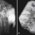
CT is the production of cross-sectional images of the body by selective absorption of a rotating x-ray or electron beam. Multiple detectors measure the transmission of the beam at multiple angles, and computer algorithms are used to form images from the data. Contrast between different tissue types is significantly higher with CT than with plain radiography, and there is more precise localization of structures on the cross-sectional imaging. The imaging plane is usually axial or axial oblique, although direct coronal images of the foot and ankle and sagittal or coronal images of the wrist and elbow can be obtained with variations in patient positioning. Axial images can be reformatted into sagittal, coronal, oblique, or complex planes,126 but the resolution depends on the section thickness of the original images and is degraded if there is patient motion during the scan. Multidetector-row CT (MDCT) allows for simultaneous generation of multiple images or a volume of data, which allows for more rapid acquisition, thinner slice thickness, and improved multiplanar reformations. Three-dimensional reformatted images with surface rendering can also be obtained and are occasionally helpful for surgical reconstruction of complex fractures or to assess bony impingement on adjacent structures (Figure 7-1).22,89
Computed Tomography With Contrast Agent Enhancement
Postarthrography CT delineates well the joint space as well as surrounding bony structures.48 Postarthrography CT of the shoulder is good at delineating the glenoid labrum. Whereas previously high-resolution shoulder images were limited to the axial plane, MDCT with thin-section imaging down to 0.625 mm thickness allows high-definition reformations in the sagittal oblique and coronal oblique planes. MDCT arthrography can be used for high-resolution imaging of the shoulder, elbow, hip, knee, and ankle when MRI is contraindicated.
Magnetic Resonance Imaging
MRI is the production of cross-sectional images of the body through placement of the imaged body part in a large, static magnetic field with a varying magnetic gradient pulsed in such a way as to allow the resonance of hydrogen to be detected.124 The data obtained are then converted by computer algorithms into cross-sectional images. These images depend on the number of mobile hydrogen atoms and specific tissue characteristics of the hydrogen. Pulse sequence parameters can be adjusted to accentuate certain inherent qualities of tissues, allowing for much higher contrast between different types of tissue (Table 7-1). For example, fat-containing tissues can be accentuated or suppressed, and water-containing tissues can be accentuated or suppressed.
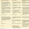
Table 7-1 Relative Advantages and Disadvantages of Magnetic Resonance Imaging and Computed Tomography
| CT | MRI | |
|---|---|---|
| Advantages | Rapid acquisition time Less sensitive to motion than MRI Detection of calcification and ossification Less artifact from metallic foreign bodies or prostheses than MRI Good patient tolerance |
Anatomic and pathologic information (proton density, T1, T2, chemical shift) Better tissue contrast than CT Direct multiplanar imaging No ionizing radiation |
| Disadvantages | Anatomic information predominantly; less pathologic information than with MRI Ionizing radiation Limited imaging planes |
More sensitive to motion than CT Longer acquisition time than CT Lower resolution for cortical bone or calcification than CT Considerable signal loss from metallic foreign bodies or prostheses Some problems with claustrophobia, although lessened with large-bore or open MRI scanners |
CT, Computed tomography; MRI, magnetic resonance imaging.
MRI has multiple available imaging planes, including complex imaging planes. Multiple magnetic gradient pulse sequences are also available to accentuate different characteristics of tissues (Table 7-2). Standard pulse sequences include T1-weighting, proton density, T2-weighting, short inversion time–inversion recovery (STIR), and fat suppression imaging. Numerous pulse sequences are available on any given magnetic resonance (MR) scanner, and different manufacturers typically use different abbreviations for the sequences. The advent of fast spin-echo sequences has shortened imaging times. However, the natural fat signal suppression on T2-weighted spin-echo images is partially lost on fast spin-echo T2-weighted images unless additional fat suppression techniques are included.
Table 7-2 Magnetic Resonance Signal Characteristics of Different Tissues
| Tissue | T1-Weighted Images | T2-Weighted Images |
|---|---|---|
| Fat | High | Low∗ |
| Cortical bone | Low | Low |
| Fatty bone marrow | High | Low∗ |
| Red bone marrow | Intermediate | Intermediate |
| Muscle | Low to intermediate | Low to intermediate |
| Tendon | Low | Low |
| Ligament | Low | Low |
| Fluid | Low | High |
| Intervertebral disk | Low | High |
| Desiccated disk | Low | Low |
∗ Low signal with routine spin-echo imaging. Fast spin-echo T2-weighted images do not show as much loss of fat signal.
STIR imaging shows additive T1 and T2 characteristics and has a high sensitivity for edema and many types of tumors. There is also suppression of the signal from fat, which causes the fat to appear dark, although some nonfat tissues can be suppressed if they have a short T1.77 Kinematic MR images are obtained as a joint is moved stepwise through a range of motion. This is useful to assess patellar tracking abnormalities.151 Kinematic imaging of the temporomandibular joint and shoulder143 can also be performed for specific clinical indications.
Magnetic Resonance Imaging With Contrast Agent Enhancement
MR arthrography with dilute gadolinium contrast material injected into joints significantly improves the delineation of many intraarticular and periarticular structures,63 including the glenoid labrum and glenohumeral ligaments,9,113 the acetabular labrum,37 a postoperative meniscus,4 and the articular cartilage. Intraarticular gadolinium can also improve differentiation of partial-thickness from full-thickness tears of the rotator cuff. Nonenhanced bursal fluid has a different signal characteristic than intraarticular gadolinium. The risks of intraarticular injection of gadolinium are the same as for arthrography and include hemorrhage, infection, and rare anaphylactic reactions. In 1085 consecutive patients injected for MR arthrography, temporarily increased joint pain, most pronounced 4 hours after injection, was the most common side effect and was related to younger age.144
Nuclear Medicine Studies
Single photon emission CT (SPECT) is an adjunct to the planar bone scan. It provides cross-sectional images of the body (axial, coronal, sagittal) using the same radioisotope emissions as a bone scan, but with a moving gamma camera. This is especially useful in the spine to show whether activity is greatest at the vertebrae anteriorly or around the facet joints or other posterior elements. The signal-to-background ratio is also improved with SPECT imaging. However, SPECT imaging takes additional time and adds expense, so it is used only for specific indications. In the patient with mechanical back pain, a bone scan can help show the level of facet joint abnormality, although the facet joint with abnormal activity might not necessarily be the one that is painful. Often the contralateral facet is painful from abnormal stresses caused by the “hot” facet joint. Bone scan with SPECT has been shown to be helpful in the identification of patients who would benefit from facet joint injection and has been shown to reduce the number of facets to be injected by clinical determination alone.121
Positron emission tomography (PET)/CT scanning, which combines radiotracer uptake in the form of a radiolabeled glucose analog with the anatomic detail of CT, shows promise in localizing infection in difficult-to-diagnose cases such as Charcot joints70 and possibly in patients with joint prostheses86 or orthopedic hardware.
Ultrasound
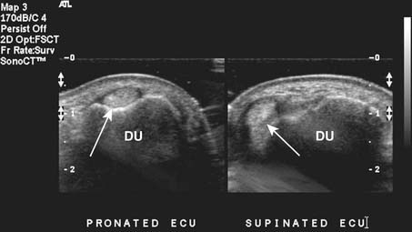
Targeted musculoskeletal ultrasound can be a useful addition in the diagnosis of musculoskeletal pathology. It is highly operator dependent and should only be performed at sites where the physicians and sonographers are specialized in musculoskeletal imaging and aware of common imaging pitfalls.68 Ultrasound can be used in patients when MRI is contraindicated secondary to MRI-incompatible devices such as pacemakers and when patients have claustrophobia in the MRI unit. Ultrasound does not use any ionizing radiation. High-resolution linear array transducers with a broad bandwidth should be used for musculoskeletal ultrasound. Ideal transducer frequency is between 7.5 and 12 MHz. Ultrasound also has the advantage of being able to dynamically visualize tendons, ligaments, and superficial structures (Figure 7-3).131
Imaging Artifacts
Plain Radiography Artifacts
On plain radiographs a common artifact is the Mach line, which, occurs when a bony edge overlaps another bone. A thin, dark line appears just adjacent to the overlapping bone and can be mistaken for a fracture (Figure 7-4).
Computed Tomography Artifacts
The three artifacts seen most commonly with CT are those of partial voluming, streak, and beam hardening. Helical and MDCT scanners can show additional artifacts.7A partial voluming artifact occurs because a CT section has a finite thickness, such as 0.625, 1.25, 2.5, or 5 mm. If a structure extends only through a portion of the section, the attenuation is averaged with that of the structure beside it in the section. For this reason, partial voluming is more likely to occur with thicker sections. Partial voluming can result in missing a fracture in the axial plane, where it is averaged with the solid bone on either side of the fracture. Use of a thinner section thickness minimizes this artifact, which is why cervical spine CT images are obtained with thin-section thickness. CT of ankle or foot fractures may be performed with a relatively thin-section thickness in both the coronal and the axial planes, which minimizes the likelihood of missing a fracture from partial voluming. Helical volumetric CT imaging can also reduce partial voluming.
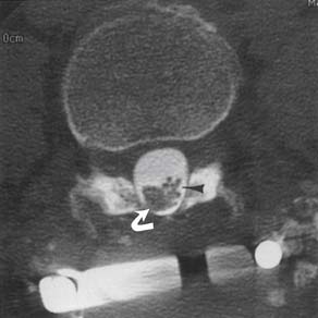
Reconstruction of the CT data to form an image assumes a constant energy of the x-ray beam as it circles around the patient. An area of increased density, such as thick bone, can attenuate the lower energy portion of the x-ray spectrum and cause a relatively higher energy beam to pass through. This difference in energy over a portion of the data stream can result in beam-hardening artifact, with variable attenuation central to the high-density bone (Figure 7-5).
Streak artifact occurs where there is an interface between tissues of very different attenuation, such as bone and air, resulting in linear streaks extending along the plane of the interface. This can be seen at the bone-air interface of sinuses or at the interface of a metal prosthesis and bone. Presence of a metal prosthesis can result in both beam-hardening and streak artifacts. Newer CT scanners with multidetector-row arrays can significantly reduce or eliminate artifact from internal fixation hardware or prostheses in concert with improved reconstruction algorithms, and allow for detection of orthopedic hardware complications.48,81,110
Magnetic Resonance Imaging Artifacts
Partial voluming can occur with MRI, in that there is a finite thickness of tissue sample to make an image, and there can be averaging of signal from tissue components within the thickness of the section. This effect can be reduced with thinner section thickness.163 Partial voluming is routinely seen on sagittal images obtained through the spine at the lateral edge of the thecal sac, where there is partial voluming of the CSF with the epidural fat. Partial voluming of the edge of the spinal cord with the adjacent CSF on sagittal images can artifactually increase the signal intensity of the cord on the most lateral images of the cord.
Magic angle artifact is a phenomenon seen on imaging of anisotropic structures that course 55 degrees (the “magic angle”) relative to the main magnetic field in the MR scanner.46,47 There is an artifactually increased signal within the structure at this angle. This artifact most commonly occurs during imaging of tendons that are anisotropic and course at a 55-degree angle to the main magnetic field, such as in the rotator cuff supraspinatus tendon168 or the ankle tendons as they course around the malleoli. The artifact is especially problematic in the rotator cuff, where increased T1 and proton density signal in the critical zone (which might course 55 degrees relative to the main magnetic field) can represent tendinopathy. A partial- or full-thickness tear of the supraspinatus should not be confused with the increased signal intensity arising from imaging at the magic angle, as T2-weighted images show more signal abnormality with tears and less magic angle effect. Signal intensity of peripheral nerves on MR neurography can increase as the nerve courses at the magic angle.28
Chemical shift artifact is seen because the resonance frequency of hydrogen varies with the structure that the hydrogen is within.163 The resonance frequency of fat is slightly different from that of water because of the different hydrogen bonds. Consequently the reconstruction algorithm can position fat slightly differently than water-containing structures, leading to artifacts in the frequency encoding direction. This can cause misregistration of fatty bone marrow in relation to soft tissues adjacent to the bone, giving an asymmetry and inaccuracy of cortical bone thickness in the extremities42 or at the vertebral endplate or cortex.
Motion artifact is usually visible on MR images as blurring or double images.163 Flow artifact from vessels or CSF can cause artifacts, either within the vessel or CSF or in a line in the phase encoding direction.85 These artifacts can often be minimized with flow compensation or saturation bands in the imaging protocol. However, if there is an unusual round focus of signal not expected within a structure, it is prudent to check if it lies in a horizontal or vertical line with a blood vessel and if it is of the same caliber.
Metal artifact occurs when either microscopic or macroscopic metal fragments cause a localized change in the homogeneity of the magnetic field. This can result in a focus of signal void with an adjacent high signal intensity ring.163 These artifacts are dramatically evident when a prosthesis or internal fixation device is present, and they appear as small foci in the postoperative patient if microscopic fragments of metal break off the drills or other instruments during surgery. A small high-signal ring or partial ring near the signal void helps differentiate this artifact from a calcification or hemosiderin. Artifact from metal can be reduced by using T2-weighted fast spin-echo techniques, rather than conventional spin-echo techniques,165 and by careful attention to scanning parameters and alignment of a prosthesis in the magnetic field.81
Ultrasound Artifacts
One of the most common sources of artifact in musculoskeletal ultrasound is from anisotropy. This phenomenon occurs because of the parallel arrangement of tendon fibers. Optimal echoes result from the ultrasound probe being oriented at 90 degrees to the tendon being scanned. When the probe is not perpendicular, decreased echoes return, and the images will show decreased echogenicity within the tendon that can be misinterpreted as a tear or tendinopathy.139 Acoustic shadowing is another potential cause of false-positive tears in tendons and results when areas overlying the tendons have a differing density or thickness, which then causes an acoustic shadow over the tendon.
Imaging of the Spine
Trauma
Imaging for spinal trauma depends on the clinical situation and presence of symptoms, neurologic deficit, and sensorium of the patient. The National Emergency X-Radiography Utilization Study prediction rule (NEXUS), the Canadian C-Spine Rule (CCR) criteria, or both are used to determine when cervical imaging is not indicated.13 For suspected cervical spine trauma the ACR appropriateness criteria have eight clinical scenarios depending on clinical criteria. Some of these include myelopathy, mechanically unstable spine, unevaluable for greater than 48 hours, suggested arterial injury, and suggested ligamentous injury. Depending on the clinical situation, when cervical imaging is indicated, CT with multiplanar reformations is usually the best initial diagnostic procedure. MR is recommended as a complementary procedure in the setting of myelopathy, instability, or ligamentous injury.
Helical CT can better delineate a fracture shown on plain radiograph, and can also disclose other vertebral fractures not seen on plain radiographs.92,109 MRI can best show any traumatic disk extrusion or spinal cord abnormality if the patient has myelopathic symptoms.45 Fast spin-echo T2-weighted images with fat suppression can show soft tissue edema or hemorrhage associated with ligamentous tearing in whiplash injuries in the acute setting.
MRI performed before and after intravenous gadolinium instillation can help differentiate vertebral collapse resulting from osteoporosis from that caused by malignancy.36
Intramedullary Abnormalities
MRI is the procedure of choice for assessing the intramedullary space–spinal cord. Six MRI patterns of intramedullary abnormalities have been defined by their appearance on T1-weighted images, before and after contrast injection, and on T2-weighted images, with a short differential diagnosis for each.17
Intramedullary primary and metastatic neoplasms are well shown on MR T2-weighted images. Most intramedullary spinal tumors enhance with gadolinium contrast agents,115 although some intramedullary astrocytomas do not enhance.150 Metastatic tumors can show a very focal enlargement of the cord as opposed to the more diffuse enlargement with primary gliomas.
The abnormalities of multiple sclerosis can be located entirely in the cervical spinal cord without brain involvement. Spinal cord multiple sclerosis plaques are characteristically peripherally located, are less than two vertebral segments in length, and occupy less than half the cross-sectional area of the cord.166 If a cord lesion is suspicious for multiple sclerosis, either by imaging or by clinical criteria, MRI of the head should be performed to look for additional lesions and to strengthen the diagnosis.
Increased T2 signal within the cord can be seen in areas of chronic compression from degenerative disk disease and from spondylosis. The likelihood of detecting increased cord signal is proportional to the severity of the clinical myelopathy and the degree of spinal canal compression. The response to surgery is less favorable in patients with an intense, well-defined, increased cord signal than in those with a faint, poorly defined signal or those with a normal signal.29
Intradural Extramedullary Abnormalities
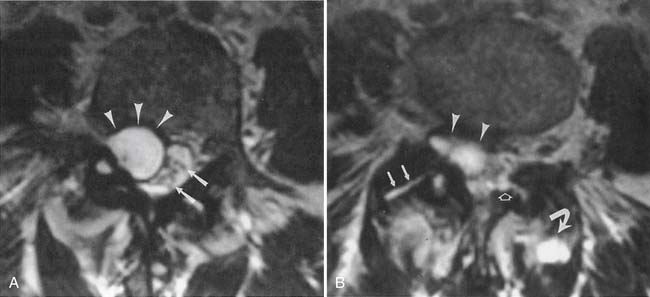
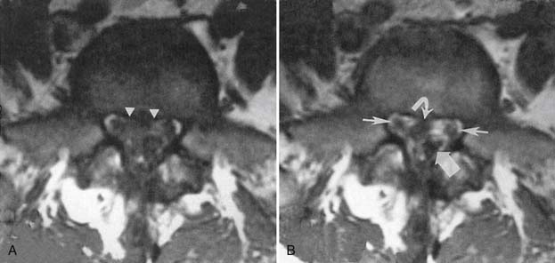
MRI with intravenous gadolinium contrast is the most sensitive imaging study for assessing abnormalities within the dural sac, including drop metastases, hematogenous leptomeningeal metastases, meningitis, and arachnoiditis (Figure 7-6).54 T2-weighted axial images without contrast can demonstrate very well the three different types of arachnoiditis seen on MRI. These include nerve clumping, tumefactive mass-like arachnoiditis, and the “empty sac” sign of the roots being attached to the thecal sac.136 Residual Pantopaque, a possible cause for arachnoiditis, can be seen as a fat signal on MRI because of its oily base.
Extradural Abnormalities
Degenerative Disk Disease and Spondylosis
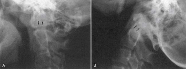
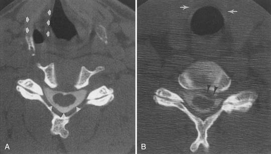
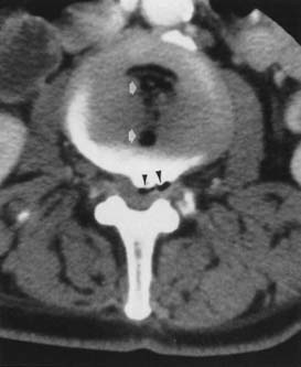
MRI is probably the single best examination to assess the intervertebral disk and surrounding structures. Plain CT and postmyelography CT, however, can both also demonstrate any morphologic abnormalities of the disk. Plain CT or postmyelography CT can show gas within the epidural space from extension through a full-thickness annular tear when the degenerated disk space contains gas, the “vacuum phenomenon” (Figure 7-7). There is little correlation between plain radiograph findings and the presence or absence of a disk extrusion.
The high incidence of asymptomatic imaging abnormalities in the general population makes it difficult to prove that an imaged abnormality is the pain generator. Diskography with pressurization of the disk space might be the most accurate method of determining whether an abnormal-appearing disk is a generator of low back pain,108 or a generator of pain radiating to the lower limbs, in a patient with no MRI evidence of nerve root compression,79,98 if the patient has unequivocal concordant symptoms during pressurization different from a control disk level. Controversy remains regarding the utility of diskography.104,108
The ACR appropriateness criteria for chronic neck pain include ratings for 10 variants, including first study, previous malignancy, previous surgery, no neurologic findings, neurologic signs or symptoms, spondylosis (without or with neurologic signs or symptoms), old trauma (without or with neurologic signs or symptoms), and bone or disk margin destruction. Five-view plain films including obliques are the first study of choice, and MRI is indicated when neurologic signs or symptoms, or bone or disk destruction is present.
Combined task forces of the North American Spine Society, American Society of Spine Radiology, and American Society of Neuroradiology have developed a standardized nomenclature and classification of lumbar disk pathology.2 Other than normal and disk desiccation, there are four general descriptions of disk disease (Figure 7-8)19:
Imaging findings of degenerative disk disease must be correlated with clinical history, physical examination findings, and possibly diagnostic injection results. Many abnormal imaging findings can be asymptomatic. In 60 asymptomatic patients aged 20 to 50 years, the prevalence of lumbar disk bulge was 20% to 28%. For protrusion it was 38% to 42%; for annular tears, 32% to 33%; for extrusion, 18%; and there were no disk sequestrations.176 Disk extrusion, sequestration, nerve root compression, endplate abnormalities, and moderate to severe facet joint osteoarthritis were rare in asymptomatic patients younger than 50 years when the prevalence among all 300 lumbar intervertebral disk levels in the study was considered.176 In 36 patients (ages 17 to 71 years) without lower back pain or sciatica, the prevalence of disk bulge was 81%, protrusion 33%, and annular tears 56%, with no extrusions noted.162 Annular tears showed contrast enhancement in 96%. Assessment of T2 high-intensity zones in the disk (annular tears) by other authors in other studies, however, showed a high correlation with pain at diskography and a low prevalence in asymptomatic patients.5,145 A high prevalence of abnormal findings on cervical MRI of asymptomatic individuals is also seen, and this increases with age.14
Intervertebral disk contour abnormalities can occur anywhere along the circumference of the disk, and can be described by location as central zone, subarticular zone (posterolateral), foraminal zone, and extraforaminal (far lateral). Foraminal zone disk abnormalities can be further described as occurring at the entrance zone, within the foramen, or at the exit zone of the foramen. The level of a herniation can be described as disk level, suprapedicle level, pedicle level, and infrapedicle level.2,179 MRI criteria to differentiate subligamentous from transligamentous disk extrusion, such as the presence of a continuous low signal intensity line posterior to the extrusion, disk extrusion size less than 50% of the size of the spinal canal, and absence of disk fragments, are unreliable.152
Small epidural hematomas can be associated with disk extrusions58 and cause a larger mass effect than can be accounted for by the extrusion itself. If the extradural mass effect trails along a root sheath toward the foramen, or has signal characteristics more like those of fluid or hemorrhage, then a small epidural hematoma should be considered.
Endplate degenerative changes associated with disk degeneration have been classified into type 1 (low T1 and high T2 signal), edema/inflammation and fibrovascular change; type 2 (high T1 and high T2 signal), fatty marrow; and type 3 (low T1 and low T2 signal), consistent with diskogenic sclerosis. Type 1 changes are more associated with lower back pain and segmental instability.127 Some of these endplate abnormalities can be associated with painful disks at discography in patients with low back pain.167,177
Facet Joint Abnormalities
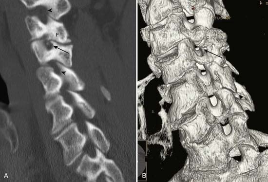
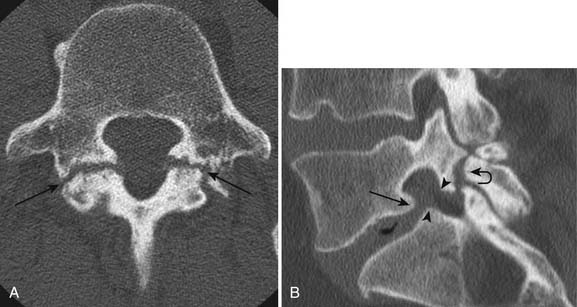
Facet and pars interarticularis abnormalities can often be seen with plain radiography. Oblique views are necessary to assess for a pars defect (spondylolysis). Thin-section CT with bone detail algorithm and sagittal reformations is the most accurate means of assessing for a pars defect, and can demonstrate any hypertrophic bone formation at the facet or pars contributing to foraminal narrowing (Figure 7-9). MRI is relatively insensitive to cortical bone defects, and so 30% of cases of lumbar spondylolysis might be undiagnosed if the physician relies on direct visualization of pars interarticularis defects.172 However, 97% of levels of spondylolysis have been shown to yield one or more secondary MRI signs, including increased sagittal diameter of the spinal canal, wedging of the posterior aspect of the vertebral body, and reactive marrow changes in the pedicle distinct from normal adjacent levels.172 Spondylolysis without spondylolisthesis can appear as widening of the sagittal dimension of the spinal canal because of dorsal subluxation of the posterior elements.171 Fluoroscopy during facet joint injection below a pars defect can show flow of the contrast agent into the pars defect and often then to the facet joint above the pars defect.
Facet degenerative changes of sclerosis, joint space narrowing, and marginal osteophytosis can be shown on plain radiographs, but are optimally demonstrated with CT. MRI is relatively insensitive for demonstrating cortical bone or osteophyte, and shows foraminal narrowing indirectly by effacement of fat around the exiting root. Cartilage degeneration and sclerosis are related to age, lumbar spinal level, and overall facet joint angle, while tropism at the facet joints may result in slightly more sclerosis, but not cartilage degeneration.56
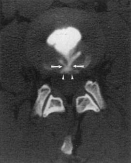
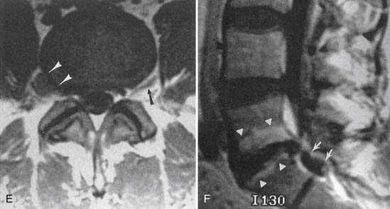
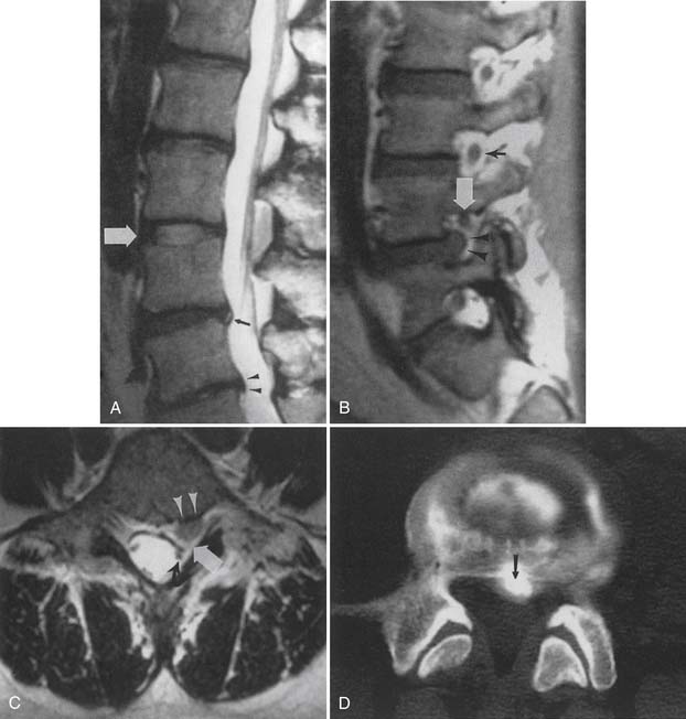
Synovial cysts are best demonstrated on MRI, where the signal characteristics of the lateral extradural mass are usually those of fluid, with low T1 and high T2 signal (Figure 7-10). This will also demonstrate the associated lateral recess stenosis. Postmyelography CT can also be diagnostic if the cyst is large enough to show water attenuation and the adjacent bony facet joint abnormalities are also shown.
Spinal Stenosis
Spinal stenosis can be described as congenital-developmental or acquired. Acquired spinal stenosis can be further classified as central, lateral recess, and foraminal. Central and lateral recess stenosis is usually caused by a combination of disk degeneration, facet hypertrophic change, and ligamentum flavum enlargement. Although MRI and CT myelography can both demonstrate narrowing of the spinal canal, myelography and postmyelographic CT have the additional benefit of showing facet bony detail and endplate osteophytosis, and allow upright weight-bearing views with flexion and extension, which often accentuate the stenosis. Symptoms of spinal stenosis are usually worse with standing or walking, and there is often a discrepancy in the imaging appearance when the patient is imaged standing versus supine or prone. Foraminal narrowing is often well demonstrated on sagittal MRI images, where there is normally an exiting root surrounded by epiradicular fat. Disk space narrowing and consequent craniocaudal foraminal narrowing, any anterolisthesis, and facet hypertrophic change can be well shown on MRI. The cross-sectional measurement of the spinal canal and intervertebral foramina has been shown to change significantly with body position on an MR scanner allowing upright and flexion-extension positioning.146 An axial compression frame has been made to allow axial loading while the patient is supine for MRI to mimic upright weight-bearing.31 Upright MR scanners might have the patient sitting, which is clinically a position that lessens symptoms of central acquired stenosis and is a position used during myelography to open the canal at a relative block to intrathecal contrast.
Nerve Roots
Lumbar nerve root enhancement can correlate with root compression and radicular symptoms.54,67 Indentation and swelling of the dorsal root ganglion can correlate with clinical symptoms.181 Transient enhancement at the affected level can be seen in asymptomatic patients in the first 6 months after surgery.43 However, in patients with residual or recurrent pain greater than 6 months after surgery, nerve root enhancement, thickening, and displacement have been shown to be associated with clinical symptoms.82
Postoperative Spine Imaging
Postoperative spine patients with residual or recurrent symptoms have special imaging considerations. Plain radiographs can often demonstrate any hardware malpositioning or failed fusion.154 If hardware is present, both CT and MRI have some limitations,165 as described previously. Flexion and extension plain radiographs can show motion at a failed fusion site. CT can show gas within the disk space (vacuum phenomenon), which is an indicator of movement. If the patient is asked to fully flex and then fully extend before CT, the vacuum phenomenon can develop and can be used as a sign of nonfusion. With posterior fusions, if the facet joint remains visible and there is resorption of fusion bone, this is an indicator of nonfusion. Persistent lucency above or below a bone plug or anterior fusion cage also suggests nonfusion if enough time has elapsed since the surgery.
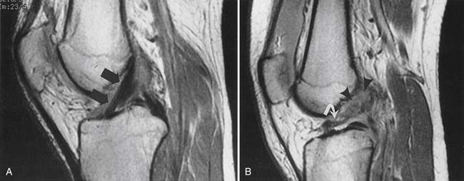
Recurrent or residual lumbar disk extrusion is best assessed with MRI before and after intravenous contrast agent injection to differentiate extruded disk material from epidural scar or fibrosis (Figure 7-11).43 Extruded disk material does not show central enhancement during the first 15 minutes after intravenous gadolinium administration, but may show some central enhancement later.65 An extruded disk can exhibit superficial enhancement because of an inflammatory component or surrounding scar (the “wrapped disk”). It might be reasonable to perform both MRI and CT myelography in problematic diagnoses, because some endplate osteophytes, calcified disk fragments, or facet osteophytes can be relatively invisible on MRI. Spearlike osteophytes impinging on the spinal cord or nerve roots might also be invisible on MRI.
The postoperative lumbar disk can show linear enhancement—two thin bands paralleling the endplates, sometimes with endplate enhancement—as well as enhancement at the curettage site in asymptomatic patients.137
Infection
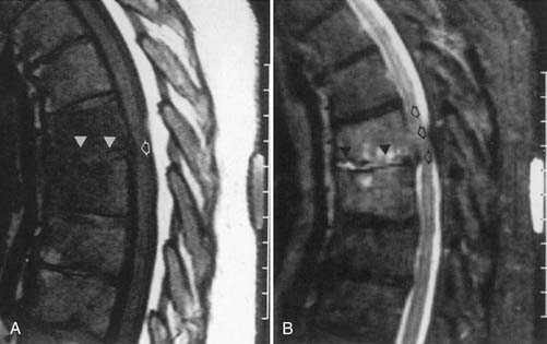
Classic plain radiographic findings of diskitis or osteomyelitis can clinch the diagnosis if disk space narrowing and endplate loss are shown. However, MRI can demonstrate the disk space narrowing, abnormal disk space signal, endplate loss, and adjacent changes in the vertebral marrow (Figure 7-12).80 Classically there is a decrease in the normal high T1 signal from fatty marrow as well as increased T2 signal in the marrow. Most degenerative narrowed disk spaces exhibit low T2 signal from desiccation. If the T2 signal within the narrowed disk is increased, diskitis is a consideration. Some noninfectious conditions such as Modic type 1 degeneration, acute Schmorl’s node, ankylosing spondylitis, SAPHO (synovitis, acne, pustulosis, hyperostosis, osteitis) syndrome, and neuropathic spine can mimic osteodiskitis on MRI.64 Modic type 1 degenerative changes with low T1 and high T2 signal can mimic the marrow changes of osteomyelitis, but are usually not associated with high disk T2 signal. Some infections can show atypical MR findings, including involvement of a single vertebra, single vertebra and disk, or two adjacent vertebrae without disk (as with tuberculosis, which might show late disk involvement).64
Tumors and Extraspinal Abnormalities
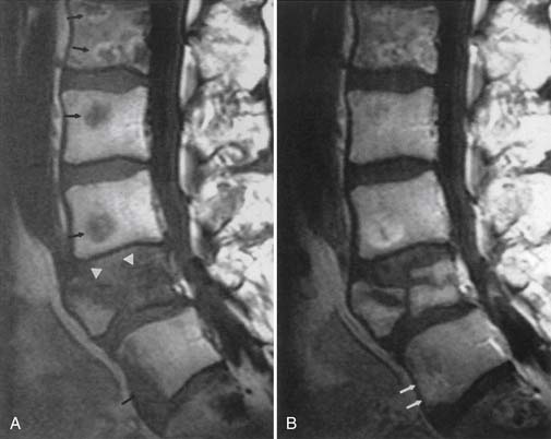
Non–contrast-enhanced MRI is more sensitive in demonstrating vertebral metastatic disease than is radionuclide bone scan. MRI is especially sensitive (relative to radionuclide bone scan or plain radiography) in demonstrating myeloma involvement.38 Bone scintigraphy, however, has the advantage of being able to survey the whole body for metastases. If the only area of interest is the vertebrae, then MRI can be both more sensitive and more specific. MRI also shows any extradural mass effect on the thecal sac, spinal cord, or nerve roots. STIR images are most sensitive for marrow-replacing tumors.97 Intravenous gadolinium administration can actually make MRI less sensitive for vertebral metastases because the usual appearance—low T1 signal metastases on a bed of high T1 signal fatty marrow—becomes less conspicuous with enhancement and increased T1 signal of the metastases (Figure 7-13).
In the setting of a primary vertebral tumor, noncontrast CT is useful to assess bony involvement, bone loss, risk for vertebral collapse, and presence of chondroid or osteoid matrix.132 MRI without and with contrast is useful to assess intraosseous or marrow involvement, paravertebral or epidural extension, and involvement of the spinal cord or nerve roots. Radionuclide bone scan can be helpful in determining whether the tumor is monostotic or polyostotic.
MRI, with its multiplanar capabilities, can demonstrate extraspinal abnormalities,111 but the field of view might be limited because the images are usually tailored (and filmed) to the spinal structures. Coronal images of the spine can show causative paraspinal abnormalities in patients with scoliosis.
Muscle Imaging
Imaging assessment of muscles includes assessment of position, size, and MR signal intensity. CT can be used to assess for position and often for the size of the muscles. Except for hemorrhage within a muscle, there is little CT attenuation difference between normal and abnormal muscle. MRI is best for assessing muscle position, size, and pathologic changes.94
Muscle position is assessed for evidence of retraction, as with a full-thickness muscle or tendon tear, such as with the supraspinatus tendon in rotator cuff injury. Anomalous muscles should not be confused with a tumor, such as an accessory soleus muscle causing an asymmetry between the calf muscles. Accessory muscles are usually asymptomatic, but can be related to palpable swelling and can result in compression neuropathies.160
Muscle trauma can be graded on a spectrum from strain (grade 1) to partial tear (grade 2) to full-thickness tear (grade 3). Muscle strain is characterized by a mild, poorly circumscribed, increased T2 signal and greater increased STIR signal, with an intact muscle and no discrete fluid collections within the muscle. There can be some fluid collection in the fascial planes between muscles or beneath the muscle capsule.18 A partial tear is characterized by a more discrete focus of increased T2 signal intensity, with possibly some disrupted muscle fibers or fluid tracking longitudinally between muscle fibers. There should be no retraction of the muscle. A full-thickness tear is characterized by retraction of the muscle and free edges, usually with material of increased T2 signal intensity in the gap.
Acute to subacute denervation of muscle results in a mildly increased T2 signal and more prominently increased STIR signal.141,178 Increased muscle signal in the acute to subacute stage changes to fatty atrophy with increased T1 signal, and loss of muscle mass in the chronic stage. Idiopathic peroneal nerve palsy can result in early changes of abnormal increased T2–STIR signal within the extensor digitorum longus and tibialis anterior muscle (Figure 7-14). Acute to subacute denervation changes can be seen in the infraspinatus and supraspinatus muscles with impingement on the suprascapular nerve by a paralabral (“ganglion”) cyst.169 Transection of a muscle with proximal innervation can result in denervation changes distal to the transection or partial transection. Neurotoxic chemotherapy can result in a patchwork appearance of muscle signal changes.
Nerve Imaging
The larger peripheral nerves can be imaged in cross-section on CT when they are surrounded by fat. They are better imaged with MRI, where they have a low T1 signal surrounded by high-signal fat, or with STIR sequences, where they have an intermediate to high signal surrounded by low-signal fat. MRI is excellent for assessing an extrinsic mass effect on nerves, such as in the spinoglenoid notch from a suprascapular paralabral cyst, or in the brachial plexus from a tumor.25 Intrinsic abnormalities of the nerves are more difficult to assess on routine MRI unless there is an enlargement of the nerve to indicate the level of abnormality. High-resolution experimental phased array surface coil imaging, however, can show areas of intrinsic nerve abnormality.90 The field of view can be relatively small with high-resolution scans, so the site of suspected abnormality needs to be established as accurately as possible before the scan.8
The ACR appropriateness criteria for plexopathy include ratings for brachial or lumbosacral plexopathy in the settings of acute onset or chronic without trauma, as a result of traumatic injury, entrapment syndromes, or posttreatment syndrome. MRI without and with contrast is rated highest; next highest is noncontrast MRI.
Targeted high-resolution ultrasound can also be helpful to diagnose compressive neuropathy in the wrist and ankle. It is particularly helpful in the diagnosis of nerve entrapment syndromes that are located superficially in osteofibrous tunnels.91
Tendon Imaging
As with muscle, CT can demonstrate tendon position and (to an extent) size, but is unable to show intrinsic abnormalities. It is also sometimes limited because adjacent muscle, ligament, and tendon can have a similar CT attenuation. Tendons can be assessed in imaging studies for position, size, and MR signal intensity.11,49,71,148,182 The multiplanar capabilities and tissue discrimination available with MRI make it the best imaging modality to assess tendons. Ultrasound can demonstrate tendon size and echogenicity as well as dynamic views of tendons in different positions with flexion, extension, abduction, and adduction.131 This can be helpful to diagnose tendon impingement107 and can also be diagnostic in the assessment of syndromes in which tendons snap painfully across joints, such as in snapping hip syndrome.117
Tendon caliber is best assessed in a true cross-section, which in some cases can require an oblique plane, as with curving of the peroneal tendons behind the lateral malleolus.71 Imaging in planes tangential to the tendon can be compromised by partial voluming with adjacent fat. Assessment of tendons should include the musculotendinous junction, where many of the traumatic injuries occur.
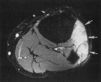
Tendon size is easily comparable between limbs as well as between adjacent tendons (Figure 7-15). Tibialis posterior tendon tears are graded from 1 to 3. Grade 1 is a partial tear with enlargement of the tendon and longitudinal split. Grade 2 is a partial tendon tear with attenuation of size and disruption of some of the tendon fibers. Grade 3 is a full-thickness tendon tear with retraction of the tendon.135 Enlargement of a tendon can be seen with an acute partial tear, and longitudinal split with fluid between the tendon fibers, with a chronic tendon tear and scar tissue increasing the girth of the tendon, as well as with acute or chronic tendonitis. The signal characteristics of the enlarged tendon help to differentiate these entities.182
The normal tendon is of very low, homogeneous T1 and T2 signal intensity. The magic angle phenomenon can artifactually increase signal intensity within the tendon when it is coursing at a 55-degree angle to the main magnetic field. The problem is greatest at the supraspinatus tendon in the rotator cuff168 and at the ankle tendons as they course around the malleoli. In these two cases the region of artifactually increased signal is unfortunately also that where pathology is most likely to be seen.
Fluid within the tendon sheath can be a normal finding in specific tendons, such as tendons of the biceps or flexor hallucis longus. This is because both of them are in communication with the joint space. Fluid within other tendon sheaths, such as in the peroneus longus tendon sheath, can be indicative of a calcaneofibular ligament tear with fluid extending from the mortise joint. Synovitis is also a consideration when fluid is seen between the tendon sheath and a normal tendon. Tenosynovitis is suspected when fluid is seen between the tendon sheath and an enlarged tendon. Fluid surrounding a tendon that has no tendon sheath, such as the Achilles tendon, is consistent with a peritenonitis, shown best on T2-weighted images with fat saturation.
Ligament Imaging
Ligaments can be indirectly assessed on plain radiographs by the presence of subluxation or dislocation, or movement with stress maneuvers. The Telos stress examination is used to assess the ankle ligaments with posteriorly directed and varus stress.26 Three-compartment arthrography is used to indirectly assess the carpal ligaments for rupture.180
Direct visualization of ligaments is best performed with MRI.∗ Ligaments are assessed for continuity, size, and signal intensity.
A ligament should be continuous between insertions, with a smooth linear or curvilinear contour. Waviness of the ligament is consistent with a tear and partial retraction. Some ligaments have a normal curvature in certain joint positions, and this should be taken into account during assessment. For example, the posterior cruciate ligament (PCL) takes a more curvilinear course with the knee in extension, and a more linear course with the knee in flexion. The course of the ligament must also be assessed, in that some complete ligament tears can heal in an abnormal position, such as a chronic anterior cruciate ligament (ACL) tear that has healed in a more horizontal position.173
Knowledge of the range of normal ligament calibers is helpful during assessment. Many ligaments, such as the anterior talofibular ligament, are uniform in thickness along their lengths.118 Others, however, comprise multiple smaller fascicles and can assume a more fan-shaped appearance, such as the posterior inferior tibiofibular ligament.118 Thickening or thinning of the ligament can occur with an acute or a chronic partial tear.
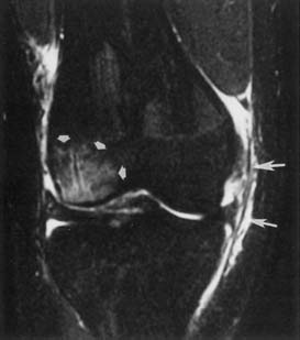
Ligaments have homogeneous, low T1 and low T2 signal intensity on MRI. Increased T1 and T2–STIR signal intensity within or around the ligament is suggestive of a sprain or partial tear. A complete tear disrupts the ligament, usually with intervening high T2 signal intensity in the acute stage (Figure 7-16). A healing or healed full-thickness ligament tear might show low T2 signal material at the site of the tear, making it more difficult to delineate the location or even the presence of a tear.173
Cartilage Imaging
Cartilage thickness cannot be directly seen on plain radiographs, although secondary changes of severe chondromalacia, such as joint space narrowing, subcortical sclerosis, and cyst formation, can be seen.62 Chondrocalcinosis is probably best detected on plain radiographs. Arthrography can demonstrate the thickness and surface contour of hyaline cartilage, as can postarthrography CT.62 MRI and MR arthrography best demonstrate cartilage thickness, contour, and any intrinsic signal abnormalities.62,133 Fat-suppressed proton density images show excellent contrast between bone, cartilage, and intraarticular fluid (Figure 7-17).133 Recent MRI advances using faster three-dimensional sequences and isotropic resolution allow for better visualization of morphology and depth of defects.55 In addition, imaging with higher field strength magnets at 3 tesla allows for accurate cartilage mapping that helps treatment planning.102
MR arthrography is superior to CT arthrography for demonstrating osseous and cartilaginous intraarticular bodies.21 MRI and CT without intraarticular contrast are less accurate than either MR arthrography or CT arthrography.
Bone Imaging
Plain radiography is the initial screening procedure for assessing fractures throughout most of the body, except in the skull, where head CT is the initial procedure of choice, and in the spine in some circumstances. Orthogonal views of the body part of interest are mandatory to exclude a fracture. Some regions require a special view, such as a mortise view in the ankle; an oblique view in the hand, wrist, and foot; and an axillary or transscapular view in the shoulder.
Non–contrast-enhanced CT with or without multiplanar reformatting is used to assess the position of fracture fragments in more complex fractures, such as those involving the wrist or the ankle and foot. Preoperative assessment of highly comminuted fractures can include CT.89
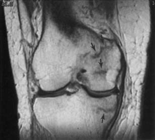
MRI is highly sensitive in the detection of reticular infractions (bone bruises), geographic infractions, stress or insufficiency fractures (Figure 7-18), osteochondral fractures, and (indirectly) macrofractures.20,114,174 Bone bruises can occur in typical locations for a given injury, such as lateral knee bone bruises with the “terrible triad of O’Donohue,” the medial patellar facet and lateral femoral condyle with a patellar dislocation,142 and anteroinferior glenoid with an anteroinferior humeral dislocation. These bone bruises can be the only sign of a previous dislocation if there has been spontaneous reduction. Some authors have thought that osteochondral defects can be a sequela of certain geographic infractions.174
Palmer et al.114 showed in 78 fractures of the knee and shoulder that MRI demonstrates prominent marrow edema with impaction fractures, and minimal edema with distraction fractures. Impaction fractures are more often missed on plain radiographs, while distraction fractures (such as Segond fractures) are more often missed on MRI.
Assessment for AVN should initially be performed with plain radiography. If the study is negative, then MRI imaging is highly sensitive and specific for AVN.35 Bone scintigraphy might be able to demonstrate AVN in earlier stages as “cold spots.” However, there is a crossover period when AVN might not be detected by bone scan, between when the bone scan is “cold” and when it becomes “hot.”35 Even if a hip radiograph indicates AVN, MRI can be considered to assess for asymptomatic AVN in the contralateral hip. MRI is useful in assessing the percent involvement of the femoral head, as well as in characterizing the marrow signal within the avascular region. The “double-line sign” of low and high T2 signal intensity at the margin of AVN is a relatively specific finding seen in 80% of cases.100
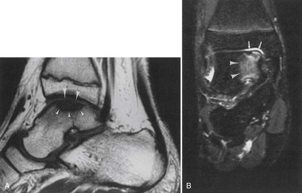
Osteochondritis dissecans in its intermediate to severe stages can be well shown on plain radiographs and non–contrast-enhanced CT scans. The earliest phase of geographic marrow edema is not visible on plain radiographs, but it is well shown on MR, especially STIR sequences (Figure 7-19). MR further shows the condition of the cartilage overlying the bony defect and can show whether there is loosening, indicated by high T2 signal fluid extending around the lesion or displacement of the osteochondral fragment.62 MRI criteria for knee osteochondritis dissecans instability in the skeletally immature patient are different than for adults.72
Bone and Soft Tissue Tumors
Non–contrast-enhanced CT can be considered for more accurate localization of bone lesions or assessment of any cartilaginous or osteoid matrix or cortical involvement. A whole body bone scan is useful to assess the entire skeleton to determine whether the lesion is single or multiple. Sometimes, bone tumor MR signal can be pathognomonic, such as with an intraosseous lipoma with uniform high T1 fatty signal, or an aneurysmal bone cyst with blood products layering. However, a significant percentage of lesions cannot be accurately categorized as benign or malignant with MRI, even with plain radiographic correlation.87 MRI is effective at demonstrating origin, margins, and extension into bone marrow or adjacent soft tissue structures, as well as subperiosteal tracking and marrow “skip” lesions.
Certain MR signal characteristics can be helpful in characterizing soft tissue masses, such as high T1 signal fat with a lipoma or liposarcoma, or low-signal hemosiderin with pigmented villonodular synovitis. MRI is useful for primary subjective identification of some benign lesions (lipoma, superficial and deep skeletal muscle hemangiomas, arteriovenous malformations, periarticular cysts, hematomas), but for tumors with a nonspecific imaging appearance, MRI is not reliable for distinguishing benign from malignant tumors.87,103 MRI of bone tumors read in isolation without correlation with radiographs can sometimes mistake benign lesions for malignant lesions.161
To be considered benign, cystic lesions must meet three MRI criteria:
A thick rim, a multiseptated thick rim, or nodular components suggest that a simple cyst is not present.
Imaging of Specific Body Regions
Shoulder Imaging
Impingement and Rotator Cuff Tears
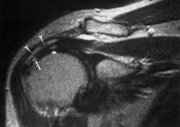
The ACR appropriateness criteria indicate routine MRI for suspected rotator cuff tear or impingement in patients older than 35 years with normal plain radiographs. Direct visualization of the tendons and muscles, as well as detection of indirect evidence of rotator cuff tear, is available with MRI (Figure 7-20).50,125,153 Coronal oblique and sagittal oblique planes of imaging (perpendicular and tangential to the plane of the glenoid) are used to obtain images parallel or perpendicular to the muscles and tendons of the rotator cuff.
Assessment of rotator cuff tendon position, thickness, and signal intensity is optimal with MRI. Early impingement results in thickening of the tendon, usually of the supraspinatus. More advanced tendinopathy results in thinning of the tendon. When the rotator cuff abnormality progresses to a partial-thickness tear, there is increased T1, proton density, and T2 signal intensity within the tendon that reflects a morphologic thinning. A full-thickness tear shows through-and-through increased signal. The position of the musculotendinous junction can be identified to determine whether there is any retraction from a full-thickness rotator cuff tear. The proximodistal and anteroposterior dimensions of a rotator cuff tear can be estimated. Unenhanced MRI is much less sensitive for partial tears than for full-thickness tears.6 A metaanalysis concludes that MR arthrography is the most sensitive and specific technique for diagnosis of full- and partial-thickness rotator cuff tears.39
Ultrasound can be used to visualize rotator cuff pathology, but is more variable in its sensitivity and specificity compared with MRI and MR arthrography for the detection of small partial-thickness tears. Visualization of the biceps tendon at the level of the bicipital groove is excellent. Specific portals or views should be used to visualize the rotator cuff, biceps tendon, and joint.16 There will be variation based on the patient’s range of motion to obtain the best possible images of the rotator cuff. For example, to obtain optimal views of the supraspinatus tendon, patients must be able to extend their arm posteriorly and place the palmar aspect of the hand against the superior aspect of their iliac crest.
Partial and complete rotator cuff tears can be seen on MRI in a significant percentage of asymptomatic individuals, the percentage increasing with age.106 MRI-evident bone and peritendinous shoulder abnormalities are highly prevalent among asymptomatic individuals, but the prevalence of subacromial spurs, humeral head cysts, subacromial-subdeltoid bursal fluid, and disruption of the peribursal fat plane in each case is closely associated with an increasing severity of MRI-evident rotator cuff abnormalities.106
In the postoperative rotator cuff repair patient with a question of complication or recurrent tear, MRI is the best imaging technique. However, scar tissue in the rotator cuff can sometimes be associated with an abnormal signal intensity pattern mimicking that of a recurrent tear. Arthrography or MR arthrography can be helpful to assess for a recurrent tear and passage of fluid through the tendon, and to differentiate the condition from the abnormal signal in the tendon from scar.101 Postarthrography CT is useful to assess for dislodgment of Mitek anchors used for rotator cuff repair.
Glenoid Labral Lesions and Instability
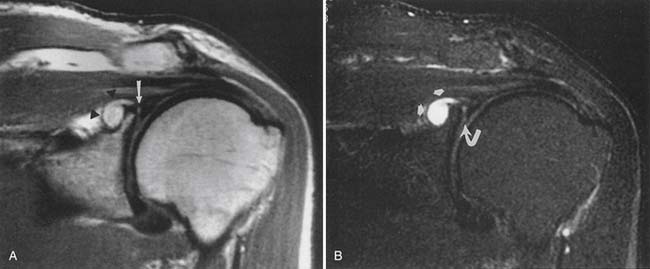
The ACR appropriateness criteria committee rates MR arthrography as the recommended imaging study when instability or a labral tear is suspected. CT can better show fractures of the bony glenoid. CT arthrography yields high-definition images of the labrum, but gives less information about other possible causes of shoulder pain.27 Unenhanced MRI59 and MR arthrography9,10 allow multiplanar imaging, which can be useful for assessing superior labral tears on coronal oblique images (Figure 7-21), the inferior glenohumeral ligament on sagittal oblique and axial images, and the biceps tendon and rotator cuff. Nonenhanced MRI does not outline the labral structures as well as MR arthrography if there is no significant effusion present, but some researchers have shown a high accuracy with unenhanced MRI.59 Some experts prefer to use MR arthrography to assess the labrum and biceps-labral complex. The glenohumeral ligaments are best shown with postarthrography MRI.10 The abduction–external rotation position has been shown to best demonstrate the inferior glenohumeral ligaments,78 but this position requires a longer imaging time and repositioning of the patient during the examination.
The labrum is evaluated for morphology, signal intensity, and position. There is variability in labral morphology, especially at the superior aspect of the anterior labrum.40,84 Superior labral anterior-to-posterior lesions and involvement of the biceps-labral complex are ideally shown after intraarticular contrast agent injection, where there is insinuation of the contrast agent between the cartilage and the superior labrum. The axial images can show a Hill-Sachs lesion or Bankhardt lesion of the bony glenoid or labrum if the patient has had a previous anteroinferior humeral dislocation.
Impingement on the suprascapular nerve, the first takeoff of the brachial plexus, is relatively common and can cause denervation of the infraspinatus and possibly supraspinatus muscles.141 Suprascapular ganglion cysts (paralabral cysts) are well demonstrated on MRI, with high T2–STIR signal intensity. It is thought that most, if not all, suprascapular ganglion cysts are associated with labral tears,169 but labral tears are often not demonstrated on MRI in these patients.
Elbow Imaging
Because of its multiplanar capabilities and excellent contrast resolution, MRI is the best modality for assessing the elbow for muscular, ligamentous, or tendinous injuries; bone marrow edema; or osteochondral injury (Figure 7-22).51,116,157 Coronal imaging ideally assesses the collateral ligaments and the extensor and flexor tendons. The annular ligament and the distal biceps tendon are best assessed on axial images.49 MR arthrography can better show partial tears of the ulnar collateral ligament than unenhanced MRI can.105,147
Lateral epicondylitis (“tennis elbow”) can manifest with increased T2 signal intensity and thickening of the common extensor tendon. Medial epicondylitis (“Little Leaguer’s elbow” in children, medial tendinosis or “golfer’s elbow” in adults) can manifest with bone marrow edema and medial epicondyle apophyseal separation in children, and with increased T2–STIR signal intensity and thickening of the common flexor pronator tendons and muscles in adults. Valgus stress on the ulnar collateral ligament can result in traction osteophytes if chronic, while acute trauma can result in a sprain, a partial tear, or a full-thickness tear, with imaging characteristics similar to those of ligament injuries elsewhere in the body.52,99
The ACR appropriateness criteria for chronic elbow pain rate plain radiographs as the initial evaluation. MRI or MR arthrography is rated highly in the setting of intraarticular osteocartilaginous body, occult injury, unstable osteochondral injury, mass, collateral ligament tear, biceps tendon tear, nerve injury, or chronic epicondylitis. Ultrasound is rated highly on appropriateness criteria for evaluating lateral and medial epicondylitis, collateral ligament tear, biceps tear, or nerve injury, as an alternative to MRI if expertise is available.
MRI can be useful for assessing ulnar nerve abnormalities at the elbow if there is an abnormality of size, signal, or position.12,66,134,157 Ultrasound of the elbow can be used to evaluate for nerve entrapment at the cubital tunnel. Examination in flexion and extension can show dynamic subluxation of the ulnar nerve.
Wrist and Hand Imaging
The ACR appropriateness criteria for acute hand and wrist trauma include 12 clinical scenarios and rate plain radiographs highest for initial assessment. In the setting of suspected wrist or hand fracture, preferably at least three radiographic views should be obtained: orthogonal anteroposterior, lateral views, and an oblique view. If a scaphoid fracture is suspected, an additional scaphoid view can be obtained that lays out the length of the scaphoid. A carpal tunnel view can be useful in a suspected fracture of the hook of the hamate. Knowledge of the clinical history and examination findings is helpful in determining which additional views are necessary to exclude a fracture. Some scaphoid fractures are occult and should be reimaged 7 to 10 days after the initial injury if there is a high suspicion of scaphoid fracture and snuffbox tenderness. The patient should be splinted until the follow-up radiograph. Alternatively, MRI is quite sensitive for occult fractures of the scaphoid20 and distal radius where there is bone marrow edema, intratrabecular hemorrhage, or both, early after fracture.156
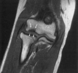
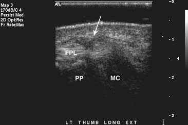
The ACR appropriateness criteria for chronic wrist pain include 10 clinical settings with initial imaging being plain radiographs. Most scenarios use MRI to evaluate the wrist if routine radiographs are normal or nondiagnostic and the patient has persistent symptoms. MR arthrography is recommended for ulnar-sided wrist pain and for suspected triangular fibrocartilage or intrinsic ligament tears.34 MRI and MR arthrography using high-resolution surface coils can provide detailed information regarding the extrinsic and intrinsic ligaments of the wrist, including the triangular fibrocartilage complex.183 MRI is also excellent for depiction of the tendons and ligaments of the finger.33 MRI is often used to help treatment planning in judging the extent of ligament and tendon injuries such as the Stener lesion.60
In the wrist and hand, ultrasound is used in the evaluation of tendon tears and tenosynovitis. Localization and verification of ganglion cysts is another useful feature of ultrasound in the wrist. Because the structures in the hand and wrist are extremely superficial, the use of a standoff pad and small-footprint, high-resolution ultrasound probe will obtain the best possible images. Flexion and extension views can be helpful to show pathology at the site of maximal pain in tendon entrapment syndromes such as trigger finger (Figure 7-23).57 When performed correctly, ultrasound has also shown good results in the depiction of ulnar collateral ligament tears in the thumb.44
Sacroiliac Joint Imaging
Anteroposterior angled and bilateral oblique views of the sacroiliac joints are the standard initial workup. MRI has been effective in the evaluation of early or active sacro-iliitis.138 STIR sequences in particular are sensitive in the detection of bone marrow edema associated with active disease. CT scanning is more helpful in the evaluation of longstanding chronic changes and the extent of osseous fusion.
Hip and Pelvis Imaging
In the trauma setting, orthogonal plain radiography is the initial imaging study. CT can be considered in the setting of more complex acetabular and pelvic fractures to aid in surgical planning.35,61,123 Fractures, muscle injuries, and soft tissue injuries can be detected with MRI of the pelvis in patients with nonrevealing radiographs after acute trauma.15,95 CT is the preferred modality for assessment of osseous-based abnormalities of the hip, and MRI is the preferred modality, after plain radiography, to image AVN, marrow replacement processes, musculoskeletal tumors, and osteomyelitis.35 MR arthrography has a much higher accuracy than nonenhanced MRI in the detection and staging of acetabular labral lesions when the labrum is being assessed for abnormalities of morphology, signal intensity, the presence or absence of a tear, and attachment to the acetabulum.37,170 MR arthrography demonstrates the characteristic findings of cam-type (large alpha angle, anterosuperior cartilage lesions, femoral neck osseous bump) and pincer-type (deep acetabulum, posteroinferior cartilage lesions) femoroacetabular impingement.119 Tannast et al.164 provide a detailed review of plain radiographic findings and potential diagnostic pitfalls in imaging of femoroacetabular impingement.
Knee Imaging
In the setting of significant acute trauma, the minimum initial examination includes orthogonal anteroposterior and lateral views. If there is a high clinical suspicion of fracture or lipohemarthrosis, then further views, such as bilateral oblique, sunrise, and/or tunnel notch, should be considered.24 Bone bruises or occult stress fractures are best shown with MRI. In a study of 84 patients with acute knee injury, MRI was shown to decrease the number of arthroscopic procedures, improve clinician diagnostic certainty, and change the management proposed before MRI.93 MRI before arthroscopy in 50 patients who met clinical criteria for knee arthroscopy showed that 42% of the arthroscopies were unnecessary.23
In the setting of knee osteoarthritis, marginal osteophytes are the most sensitive radiographic feature of osteoarthritis of the tibiofemoral joint.73 When comparing MRI findings and clinical features, moderate and massive joint effusion was associated with knee pain and stiffness and patellofemoral osteophyte or more than four osteophytes in the entire knee were associated with pain.75 In the knee, ultrasound can be used to evaluate the size of an effusion, prepatellar bursitis, or Baker’s cyst. It can also be used to evaluate quadriceps tendon and patellar tendon pathology.
Meniscal Injuries
MRI is the best method of assessing the meniscus in a patient who has not previously undergone surgery.30,69 MRI is noninvasive and multiplanar, allowing assessment of the meniscus. Radial imaging planes can be obtained that give similar views to those seen with knee arthrography.
Menisci are described according to the following scheme:
In a series of 400 knee MRI studies with 333 meniscal tears, 6% of tears found on arthroscopy could not be identified on routine MRI, even in retrospect.41 False-positive diagnoses in the 400 patients occurred in 1.5% because of healed tears or tears missed at arthroscopy.
In the setting of a postsurgical meniscus where the morphology can be abnormal and inherent degenerative change extends to the articular surface, MR arthrography 4 can be considered to determine whether the fluid extends into a tear in the meniscus. Comparison with previous studies can be helpful in assessing for recurrent tear versus postoperative change. The two best signs of recurrent tear of the postoperative meniscus on routine MRI are (1) a line of abnormal meniscal signal intensity extending to an articular surface on proton density–weighted image; and (2) fluid extending into a linear area on T2-weighted images.83
Knee Ligament Injuries
The cruciate ligaments,130,159,173 the medial collateral ligament,149 and the lateral collateral ligament complex are best shown with multiplanar MRI. Again, the ligaments are assessed for continuity, caliber, and signal intensity. There is a continuum of sprain, partial tear, and full-thickness tear in the setting of ligamentous injury, similar to what is seen in ligaments elsewhere in the body.
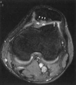
Discontinuity of the ACL on sagittal and axial MRI planes and failure of the fascicles to parallel Blumensaat’s line are the most accurate MRI signs of ACL tear (Figure 7-24).130 Multiple other indirect signs are good predictors of ACL tear, including disruption of the fascicles, a posterolateral tibial bruise, a buckled PCL, a positive PCL line sign, a positive posterior femoral line sign, displacement of the lateral meniscus more than 3.5 mm posteriorly, displacement of the tibia more than 7 mm anteriorly, and a lateral femoral sulcus deeper than 1.5 mm.53,130 In 20 patients with two different sagittal MRI sequences of the ACL showing intact fibers on one sequence and disrupted or poorly seen fibers on the other sequence (discordant findings), the ACL fibers were found to be intact on arthroscopy.155 A combination of plain radiography and MRI best assesses for complications after ACL repair.128
Patellofemoral Abnormalities
Patellofemoral abnormalities are best assessed in the axial and sagittal planes on MRI.158 Fat-suppressed proton density MRI shows excellent contrast between the articular cartilage, bone, and any joint fluid.96,133 Grading of chondromalacia is most accurate on axial MRI. Additionally, MRI can demonstrate patella baja or alta and the patellar position within the trochlear groove. Kinematic MRI studies are available to assess patellar tracking151 and can show subluxation in certain positions. This can decrease or increase with knee flexion, depending on the cause of the tracking abnormality. Plain radiographs might or might not show patellar subluxation, depending on the degree of knee flexion used to obtain the axial patellar (sunrise) view. Routine MR images can also show the stigmata of patellar tracking disorders by showing edema in the soft tissues and fat pad adjacent to the patella, as well as characteristic patterns of chondromalacia.32 Dynamic sonography may be used to determine whether a medial plica interferes dynamically with the patellofemoral joint and might be amenable to arthroscopic resection.112
Ankle and Foot Imaging
A three-view plain radiography series that includes anteroposterior, lateral, and mortise views is considered the most appropriate by the ACR appropriateness criteria in patients with suspected ankle injury meeting Ottawa rules. Fluoroscopy with stress views can be necessary to assess for Lisfranc fracture dislocations. CT with reformations is often useful for preoperative planning in patients with complex comminuted fractures of the foot and ankle, and can alter clinical management.89
In seven clinical scenarios of chronic ankle pain, the ACR appropriateness criteria list plain radiographs as the initial imaging study, with MRI or CT the next study for several scenarios. The ACR appropriateness criteria for chronic foot pain list plain radiographs as the most appropriate initial imaging study, and then MRI as highly appropriate in many of the 10 clinical scenarios listed. Bone scan is considered highly appropriate to assess for complex regional pain syndrome if plain radiographs are not diagnostic. Chronic ankle instability can be detected with a Telos stress examination using posteriorly directed or varus stress, although MR arthrography is more accurate and sensitive in the detection of anterior talofibular ligament tears.26 In the patient with more diffuse foot pain of no definite cause, a radionuclide bone scan can often localize the abnormality to a specific joint or joints. Tarsal coalition can be evident on plain radiographs and is clearly shown on CT if it is a bony coalition. Sometimes MRI will more effectively show a fibrous coalition.175 The ACR appropriateness criteria for suspected osteomyelitis of the foot in the patient with diabetes mellitus rate plain radiographs and MRI without and with contrast highly and complementary.
MRI of the ankle or foot provides excellent delineation of ligaments,26,74 tendons,71,135,148 and any abnormal bone marrow signal to indicate AVN or a bone bruise or stress fracture. In 81 patients referred for MRI of the foot and ankle by a group of four orthopedic surgeons and podiatrists, the post-MRI diagnosis differed from the pre-MRI diagnosis in 47% of patients, and treatment plans were changed in 34%.3 The Achilles tendon is ideally shown with MRI in the sagittal and axial planes. MRI can be helpful in differentiating partial tears from tendonitis or peritenonitis. The tendon is assessed for continuity, caliber, and signal intensity, as elsewhere in the body.
1. American College of Radiology. ACR appropriateness criteria. Available at: http://www.acr.org/SecondaryMainMenuCategories/quality_safety/app_criteria. Accessed March 17, 2010.
2. American Society of Neuroradiology. Nomenclature and classification of lumbar disc pathology. Available at: http://www.asnr.org/spine_nomenclature/. Accessed March 17, 2010.
3. Anzilotti K.Jr., Schweitzer M.E., Hecht P., et al. Effect of foot and ankle MR imaging on clinical decision making. Radiology. 1996;201:515-517.
4. Applegate G.R., Flannigan B.D., Tolin B.S., et al. MR diagnosis of recurrent tears in the knee: value of intraarticular contrast material. AJR Am J Roentgenol. 1993;161:821-825.
5. Aprill C., Bogduk N. High intensity zone: a diagnostic sign of painful lumbar disc on magnetic resonance imaging. Br J Radiol. 1992;65:361-369.
6. Balich S.M., Sheley R.C., Brown T.R., et al. MR imaging of the rotator cuff tendon: interobserver agreement and analysis of interpretive errors. Radiology. 1997;204:191-194.
7. Barrett J.F., Keat N. Artifacts in CT: recognition and avoidance. Radiographics. 2004;24:1679-1691.
8. Bashir W.A., Connell D.A. Imaging of entrapment and compressive neuropathies. Semin Musculoskelet Radiol. 2008;12:170-181.
9. Beltran J., Bencardino J., Mellado J., et al. MR arthrography of the shoulder: variants and pitfalls. Radiographics. 1997;17:1403-1412.
10. Beltran J., Rosenberg Z.S., Chandnani V.P., et al. Glenohumeral instability: evaluation with MR arthrography. Radiographics. 1997;17:657-673.
11. Bencardino J.T. MR imaging of tendon lesions of the hand and wrist. Magn Reson Imaging Clin N Am. 2004;12:333-347.
12. Bencardino J.T., Rosenberg Z.S. Entrapment neuropathies of the shoulder and elbow in the athlete. Clin Sports Med. 2006;25:465-487.
13. Blackmore C.C. Evidence-based imaging evaluation of the cervical spine in trauma. Neuroimaging Clin N Am. 2003;13:283-291.
14. Boden S.D., McCowin P.R., Davis D.O., et al. Abnormal magnetic resonance scans of the cervical spine in asymptomatic subjects: a prospective investigation. J Bone Joint Surg Am. 1990;72:1178-1184.
15. Bogost G.A., Lizerbram E.K., Crues J.V.III. MR imaging in evaluation of suspected hip fracture: frequency of unsuspected bone and soft-tissue injury. Radiology. 1995;197:263-267.
16. Bouffard J.A., Lee S.M., Dhanju J. Ultrasonography of the shoulder. Semin Ultrasound CT MR. 2000;21:164-191.
17. Bourgouin P.M., Lesage J., Fontaine S., et al. Pattern approach to the differential diagnosis of intramedullary spinal cord lesions on MR imaging. AJR Am J Roentgenol. 1998;170:1645-1649.
18. Brandser E.A., El-Khoury G.Y., Kathol M.H., et al. Hamstring injuries: radiographic, conventional tomographic, CT, and MR imaging characteristics. Radiology. 1995;197:257-262.
19. Brant-Zawadski M.N., Jensen M.C., Obuchowski N., et al. Interobserver and intraobserver variability in interpretation of lumbar disc abnormalities: a comparison of two nomenclatures. Spine. 1995;20:1257-1264.
20. Breitenseher M.J., Metz V.M., Gilula L.A., et al. Radiographically occult scaphoid fractures: value of MR imaging in detection. Radiology. 1997;203:245-250.
21. Brossman J., Preidler K.W., Daenen B., et al. Imaging of osseous and cartilaginous intraarticular bodies in the knee: comparison of MR imaging and MR arthrography with CT and CT arthrography in cadavers. Radiology. 1996;200:509-517.
22. Buckwalter K.A., Farber J.M. Application of multidetector CT in skeletal trauma. Semin Musculoskelet Radiol. 2004;8:147-156.
23. Bui-Mansfield L.T., Youngberg R.A., Warme W., et al. Potential cost savings of MR imaging obtained before arthroscopy of the knee: evaluation of 50 consecutive patients. AJR Am J Roentgenol. 1997;168:913-918.
24. Capps G.W., Hayes C.W. Easily missed injuries around the knee. Radiographics. 1994;14:1191-1210.
25. Castillo M. Imaging the anatomy of the brachial plexus. AJR Am J Roentgenol. 2005;185:S196-S204.
26. Chandnani V.P., Harper M.T., Ficke J.R., et al. Chronic ankle instability: evaluation with MR arthrography, MR imaging, and stress radiography. Radiology. 1994;192:189-194.
27. Chandnani V.P., Yeager T.D., DeBerardino T., et al. Glenoid labral tears: prospective evaluation with MR imaging, MR arthrography, and CT arthrography. AJR Am J Roentgenol. 1993;161:1229-1235.
28. Chappell K.E., Robson M.D., Stonebridge-Foster A., et al. Magic angle effects in MR neurography. Am J Neuroradiol. 2004;25:431-440.
29. Chen C.J., Lyu R.K., Lee S.T., et al. Intramedullary high signal intensity on T2-weighted MR images in cervical spondylotic myelopathy: prediction of prognosis with type of intensity. Radiology. 2001;221:789-794.
30. Cheung L.P., Li K.C.P., Hollett M.D., et al. Meniscal tears of the knee: accuracy of detection with fast spin-echo MR imaging and arthroscopic correlation in 293 patients. Radiology. 1997;203:508-512.
31. Choi D.S.J., Tassi G.P., Libes R.B. Axial compression frame for MRI of thoracolumbar spine. AJR Am J Roentgenol. 2007;189:1175-1178.
32. Chung C.B., Skaf A., Roger B., et al. Patellar tendon–lateral femoral condyle friction syndrome. Skeletal Radiol. 2001;30:694-697.
33. Clavero J.A., Alomar X., Monill J.M., et al. MR imaging of ligament and tendon injuries of the fingers. Radiographics. 2002;22:237-256.
34. Coggins C.A. Imaging of ulnar-sided wrist pain. Clin Sports Med. 2006;25:505-526.
35. Conway W.F., Totty W.G., McEnery K.W. CT and MR imaging of the hip. Radiology. 1996;198:297-307.
36. Cuenod C.A., Laredo J.D., Chevret S., et al. Acute vertebral collapse due to osteoporosis or malignancy: appearance on unenhanced and gadolinium-enhanced MR images. Radiology. 1996;199:541-549.
37. Czerny C., Hofmann S., Neuhold A., et al. Lesions of the acetabular labrum: accuracy of MR imaging and MR arthrography in detection and staging. Radiology. 1996;200:225-230.
38. Daffner R.H., Lupetin A.R., Dash N., et al. MRI in the detection of malignant infiltration of bone marrow. AJR Am J Roentgenol. 1986;146:353-358.
39. De Jesus J.O., Parker L., Frangos A.J., et al. Accuracy of MRI, MR arthrography, and ultrasound in the diagnosis of rotator cuff tears: a meta-analysis. AJR Am J Roentgenol. 2009;192:1701-1707.
40. DeMaeseneer M., VanRoy F., Lenchik L., et al. CT and MR arthrography of the normal and pathologic anterosuperior labrum and labral-bicipital complex. Radiographics. 2000;20:S67-S81.
41. De Smet A.A., Tuite M.J., Norris M.A., et al. MR diagnosis of meniscal tears: analysis of causes of errors. AJR Am J Roentgenol. 1994;163:1419-1423.
42. Dick B.W., Mitchell D.G., Burk D.L., et al. The effect of chemical shift misrepresentation on cortical bone thickness on MR imaging. AJR Am J Roentgenol. 1988;15:537-538.
43. Dina T.S., Boden S.D., Davis D.O. Lumbar spine after surgery for herniated disk: imaging findings in the early postoperative period. AJR Am J Roentgenol. 1995;164:665-671.
44. Ebrahim F.S., DeMaeseneer M., Jager T., et al. US diagnosis of UCL tears of the thumb and Stener lesions. Radiographics. 2006;26:1007-1020.
45. El-Khoury G.Y., Kathol M.H., Daniel W.W. Imaging of acute injuries of the cervical spine: value of plain radiography, CT, and MR imaging. AJR Am J Roentgenol. 1995;164:43-50.
46. Erickson S.J., Cox I.H., Hyde J.S., et al. Effect of tendon orientation on MR imaging signal intensity: a manifestation of the “magic angle” phenomenon. Radiology. 1991;181:389-392.
47. Erickson S.J., Prost R.W., Timins M.E. The “magic angle” effect: background physics and clinical relevance. Radiology. 1993;188:23-25.
48. Farber J.M. CT arthrography and postoperative musculoskeletal imaging with multichannel computed tomography. Semin Musculoskelet Radiol. 2004;8:157-166.
49. Fitzgerald S.W., Curry D.R., Erickson S.J., et al. Distal biceps tendon injury: MR imaging diagnosis. Radiology. 1994;191:203-206.
50. Fritz R.C., Stoller O.W. MR imaging of the rotator cuff. Magn Reson Imaging Clin N Am. 1997;5:735-754.
51. Fritz R.C., Steinbach L.S., Tirman P.F.J., et al. MR imaging of the elbow. An update. Radiol Clin North Am. 1997;35:117-144.
52. Gaary E.A., Potter H.G., Altcheck D.W. Medial elbow pain in the throwing athlete: MR imaging evaluation. AJR Am J Roentgenol. 1997;168:795-800.
53. Gentili A., Seeger L.L., Yao L., et al. Anterior cruciate ligament tear: indirect signs at MR imaging. Radiology. 1994;193:835-840.
54. Georgy B.A., Snow R.D., Hesselink J.R. MR imaging of spinal nerve roots: techniques, enhancement patterns, and imaging findings. AJR Am J Roentgenol. 1996;166:173-179.
55. Gold G.E., Chen C.A., Koo S., et al. Recent advances in MRI of articular cartilage. AJR Am J Roentgenol. 2009;193:628-638.
56. Grogan J., Nowicki B.H., Schmidt T.A., et al. Lumbar facet joint tropism does not accelerate degeneration of the facet joints. Am J Neuroradiol. 1997;18:1325-1329.
57. Guerini H., Pessis E., Theumann N., et al. Sonographic appearance of trigger fingers. J Ultrasound Med. 2008;27:1407-1413.
58. Gundry C.R., Heithoff K.B. Epidural hematoma of the lumbar spine: 18 surgically confirmed cases. Radiology. 1993;187:427-431.
59. Gusmer P.B., Potter H.G., Schatz J.A., et al. Labral injuries: accuracy of detection with unenhanced MR imaging of the shoulder. Radiology. 1996;200:519-524.
60. Haramati N., Hiller N., Dowdle J., et al. MRI of the Stener lesion. Skeletal Radiol. 1995;24:515-518.
61. Harris J.H.Jr., Coupe K.J., Lee J.S., et al. Acetabular fractures revisited: part 2, a new CT-based classification. AJR Am J Roentgenol. 2004;182:1367-1375.
62. Hayes C.W., Conway W.F. Evaluation of articular cartilage: radiographic and cross-sectional imaging techniques. Radiographics. 1992;12:409-428.
63. Helgason J.W., Chandnani V.P., Yu J.S. MR arthrography: a review of current technique and applications. AJR Am J Roentgenol. 1997;168:1473-1480.
64. Hong S.H., Choi J.Y., Lee J.W., et al. MR imaging assessment of the spine: infection or an imitation? Radiographics. 2009;29:599-612.
65. Hueftle M.G., Modic M.T., Ross J.S., et al. Lumbar spine: postoperative MR imaging with Gd-DTPA. Radiology. 1988;167:817-824.
66. Husarik D.B., Saupe N., Pfirrmann C.W.A., et al. Elbow nerves: MR findings in 60 asymptomatic subjects: normal anatomy, variants, and pitfalls. Radiology. 2009;252:148-156.
67. Itoh R., Murata K., Kamata M., et al. Lumbosacral nerve root enhancement with disk herniation on contrast-enhanced MR. Am J Neuroradiol. 1996;17:1619-1625.
68. Jamader D.A., Robertson B.L., Jacobson J.A., et al. Musculoskeletal sonography: important imaging pitfalls. AJR Am J Roentgenol. 2010;194:216-225.
69. Jee W.H., Mc Cauley T.R., Kim J.H., et al. Meniscal tear configurations: categorization with MR imaging. AJR Am J Roentgenol. 2003;180:92-97.
70. Keidar Z., Miltianu D., Melamed E., et al. The diabetic foot: initial experience with 18F-FDG PET/CT. J Nucl Med. 2005;46:444-449.
71. Khoury N.J., El-Khoury G.Y., Saltzman C.L., et al. Peroneus longus and brevis tendon tears: MR imaging evaluation. Radiology. 1996;200:833-841.
72. Kijowski R., Blankenbaker D.G., Shinki K., et al. Juvenile versus adult osteochondritis dissecans of the knee: appropriate MR imaging criteria for instability. Radiology. 2008;248:571-578.
73. Kijowski R., Blankenbaker D.G., Stanton P.T., et al. Radiographic findings of osteoarthritis versus arthroscopic findings of articular cartilage degeneration in the tibiofemoral joint. Radiology. 2006;239:818-824.
74. Klein M.A. MR imaging of the ankle: normal and abnormal findings in the medial collateral ligament. AJR Am J Roentgenol. 1994;162:377-383.
75. Kornaat P.R., Bloem J.L., Ceulemans R.Y.T., et al. Osteoarthritis of the knee: association between clinical features and MR imaging findings. Radiology. 2006;239:811-817.
76. Korner M., Weber C.H., Wirth S., et al. Advances in digital radiography: physical principles and system overview. Radiographics. 2007;27:675-686.
77. Krinsky G., Rofsky N.M., Weinreb J.C. Nonspecificity of short inversion time inversion recovery (STIR) as a technique of fat suppression: pitfalls in image interpretation. AJR Am J Roentgenol. 1996;166:523-526.
78. Kwak S.M., Brown R.R., Trudell D., et al. Glenohumeral joint: comparison of shoulder positions at MR arthrography. Radiology. 1998;208:375-380.
79. Lebwohl N.H. Diskography for the diagnosis of radiculopathy without nerve root compression. Am J Neuroradiol. 1995;16:1614-1615.
80. Ledermann H.P., Schweitzer M.E., Morrison W.B., et al. MR imaging findings in spinal infections: rules or myths? Radiology. 2003;228:506-514.
81. Lee M.J., Kim S., Lee S.A., et al. Overcoming artifacts from metallic orthopedic implants at high-field-strength MR imaging and multi-detector CT. Radiographics. 2007;27:791-803.
82. Lee Y.S., Choi E.S., Song C.J. Symptomatic nerve root changes on contrast-enhanced MR imaging after surgery for lumbar disk herniation. Am J Neuroradiol. 2009;30:1062-1067.
83. Lim P.S., Schweitzer M.E., Bhatia M., et al. Repeat tear of postoperative meniscus: potential MR imaging signs. Radiology. 1999;210:183-188.
84. Liou J.T.S., Wilson A.J., Totty W.G., et al. The normal shoulder: common variations that simulate pathologic conditions at MR imaging. Radiology. 1993;186:435-441.
85. Lisanti C., Carlin C., Banks K.P., et al. Normal MRI appearance and motion-related phenomena of CSF. AJR Am J Roentgenol. 2007;188:716-725.
86. Love C., Tomas M.B., Tronco G.G., et al. FDG PET of infection and inflammation. Radiographics. 2005;25:1357-1368.
87. Ma L.D., Frassica F.J., Scott W.W.Jr., et al. Differentiation of benign and malignant musculoskeletal tumors: potential pitfalls with MR imaging. Radiographics. 1995;15:349-366.
88. Ma L.D., McCarthy E.F., Bluemke D.A., et al. Differentiation of benign from malignant musculoskeletal lesions using MR imaging: pitfalls in MR evaluation of lesions with a cystic appearance. AJR Am J Roentgenol. 1998;170:1251-1258.
89. Magid D., Michelson J.D., Ney D.R., et al. Adult ankle fractures: comparison of plain films and interactive two- and three-dimensional CT scans. AJR Am J Roentgenol. 1990;154:1017-1023.
90. Maravilla K.R., Bowen B.C. Imaging of the peripheral nervous system: evaluation of peripheral neuropathy and plexopathy. Am J Neuroradiol. 1998;19:1011-1023.
91. Martinoli C., Bianchi S., Gandolfo N., et al. US of nerve entrapments in osteofibrous tunnels of the upper and lower limb. Radiographics. 2000;20:S199-S217.
92. Mathen R., Inaba K., Munera F., et al. Prospective evaluation of multislice computed tomography versus plain radiographic cervical spine clearance in trauma patients. J Trauma. 2007;62:1427-1431.
93. Maurer E.J., Kaplan P.A., Dussault R.G., et al. Acutely injured knee: effect of MR imaging on diagnostic and therapeutic decisions. Radiology. 1997;204:799-805.
94. May D.A., Disler D.G., Jones E.A., et al. Abnormal signal intensity in skeletal muscle at MR imaging: patterns, pearls, and pitfalls. Radiographics. 2000;20:S295-315.
95. May D.A., Purins J.L., Smith D.K. MR imaging of occult traumatic fractures and muscular injuries of the hip and pelvis in elderly patients. AJR Am J Roentgenol. 1996;166:1075-1078.
96. McCauley T.R. MR imaging of chondral and osteochondral injuries of the knee. Radiol Clin North Am. 2002;40:1095-1107.
97. Mehta R.C., Marks M.P., Hinks R.S., et al. MR evaluation of vertebral metastases: T1-weighted, short-inversion-time inversion recovery, fast spin-echo, and inversion-recovery fast spin-echo sequences. Am J Neuroradiol. 1995;16:281-288.
98. Milette P.C., Fontaine S., Lepanto L., et al. Radiating pain to the lower extremities caused by lumbar disk rupture without spinal nerve root involvement. Am J Neuroradiol. 1995;16:1605-1613.
99. Mirowitz S.A., London S.L. Ulnar collateral ligament injury in baseball pitchers: MR imaging evaluation. Radiology. 1992;185:573-576.
100. Mitchell D.G., Rao V.M., Dalinka M.K., et al. Femoral head avascular necrosis: correlation of MR imaging, radiographic staging, radionuclide imaging, and clinical findings. Radiology. 1987;162:709-715.
101. Mohana-Borges A.V.R., Chung C.B., Resnick D. MR imaging and MR arthrography of the postoperative shoulder: spectrum of normal and abnormal findings. Radiographics. 2004;24:69-85.
102. Mosher T.J. Musculoskeletal imaging at 3T: current techniques and future applications. Magn Reson Imaging Clin N Am. 2006;14:63-76.
103. Moulton J.S., Blebea J.S., Dunco D.M., et al. MR imaging of soft-tissue masses: diagnostic efficacy and value of distinguishing between benign and malignant lesions. AJR Am J Roentgenol. 1995;164:1191-1199.
104. Nachemson A. Lumbar discography: where are we today [editorial]? Spine. 1989;14:555-557.
105. Nakanishi K., Masatomi T., Ochi T., et al. MR arthrography of the elbow: evaluation of the ulnar collateral ligament of the elbow. Skeletal Radiol. 1996;25:629-634.
106. Needell S.D., Zlatkin M.B., Sher J.S., et al. MR imaging of the rotator cuff: peritendinous and bone abnormalities in an asymptomatic population. AJR Am J Roentgenol. 1996;166:863-867.
107. Neustadter J., Raikin S.M., Nazarian L.N. Dynamic sonographic evaluation of peroneal tendon subluxation. AJR Am J Roentgenol. 2004;183:985-988.
108. North American Spine Society. Position statement on discography. Spine. 1988;13:1343.
109. Nunez D.B., Zuluaga A., Fuentes-Bernardo D.A., et al. Cervical spine trauma: how much more do we learn by routinely using helical CT? Radiographics. 1996;16:1307-1318.
110. Ohashi K., El-Khoury G.Y., Bennett D.L., et al. Orthopedic hardware complications diagnosed with multi-detector row CT. Radiology. 2005;237:570-577.
111. Olson E.M., Wong W.H.M., Hesselink J.R. Extraspinal abnormalities detected on MR images of the spine. AJR Am J Roentgenol. 1994;162:679-684.
112. Paczesny L., Kruczyriski J. Medial plica syndrome of the knee: diagnosis with dynamic sonography. Radiology. 2009;251:439-446.
113. Palmer W.E., Caslowitz P.L. Anterior shoulder instability: diagnostic criteria determined from prospective analysis of 121 MR arthrograms. Radiology. 1995;197:819-825.
114. Palmer W.E., Levine S.M., Dupuy D.E. Knee and shoulder fractures: association of fracture detection and marrow edema on MR images with mechanism of injury. Radiology. 1997;204:395-401.
115. Parizel P.M., Baleriaux D., Rodesch G., et al. Gd-DTPA–enhanced MR imaging of spinal tumors. Am J Neuroradiol. 1989;10:249-258.
116. Patten R.M. Overuse syndromes and injuries involving the elbow: MR imaging findings. AJR Am J Roentgenol. 1995;164:1205-1211.
117. Pelsser V., Cardinal E., Hobden R., et al. Extraarticular snapping hip: sonographic findings. AJR Am J Roentgenol. 2001;176:67-73.
118. Perrich K.D., Goodwin D.W., Hecht P.J., et al. Ankle ligaments on MRI: appearance of normal and injured ligaments. AJR Am J Roentgenol. 2009;193:687-695.
119. Pfirrmann C.W.A., Mengiardi B., Dora C., et al. Cam and pincer femeroacetabular impingement: characteristic MR arthrographic findings in 50 patients. Radiology. 2006;240:778-785.
120. Plancher K.D., Ho C.P., Cofield S.S., et al. Role of MR imaging in the management of skier’s thumb injuries. Magn Reson Imaging Clin N Am. 1999;7:73-84.
121. Pneumaticos S.G., Chatzioannou S.N., Hipp J.A., et al. Low back pain: prediction of short-term outcome of facet joint injection with bone scintigraphy. Radiology. 2006;238:693-698.
122. Pobiel R.S., Schellhas K.P., Pollei S.R., et al. Diskography: infectious complications from a series of 12,634 cases. Am J Neuroradiol. 2006;27:1930-1932.
123. Potok P.S., Hopper K.D., Umlauf M.J. Fractures of the acetabulum: imaging, classification, and understanding. Radiographics. 1995;15:7-23.
124. Prost R., Czervionke L.F. How does an MR scanner operate? Am J Neuroradiol. 1994;15:1383-1386.
125. Quinn S.F., Sheley R.C., Demlow T.A., et al. Rotator cuff tendon tears: evaluation with fat-suppressed MR imaging with arthroscopic correlation in 100 patients. Radiology. 1995;195:497-501.
126. Rabassa A.E., Guinto F.C.Jr., Crow W.N., et al. CT of the spine: value of reformatted images. AJR Am J Roentgenol. 1993;161:1223-1227.
127. Rahme R., Moussa R. The Modic vertebral endplate and marrow changes: pathologic significance and relation to low back pain and segmental instability of the lumbar spine. Am J Neuroradiol. 2008;29:838-842.
128. Recht M.P., Piraino D.W., Applegate G., et al. Complications after anterior cruciate ligament reconstruction: radiographic and MR findings. AJR Am J Roentgenol. 1996;167:705-710.
129. Rijke A.M., Goitz H.T., McCue F.C., et al. Stress radiography of the medial elbow ligaments. Radiology. 1994;191:213-216.
130. Robertson P.L., Schweitzer M.E., Bartolozzi A.R., et al. Anterior cruciate ligament tears: evaluation of multiple signs with MR imaging. Radiology. 1994;193:829-834.
131. Robinson P. Sonography of common tendon injuries. AJR Am J Roentgenol. 2009;193:607-618.
132. Rodallec M.H., Feydy A., Larousserie F., et al. Diagnostic imaging of solitary tumors of the spine: what to do and say. Radiographics. 2008;28:1019-1041.
133. Rose P.M., Demlow T.A., Szumowski J., et al. Chondromalacia patellae: fat-suppressed MR imaging. Radiology. 1994;193:437-440.
134. Rosenberg Z.S., Beltran J., Cheung Y.Y., et al. The elbow: MR features of nerve disorders. Radiology. 1993;188:235-240.
135. Rosenberg Z.S., Cheung Y., Jahss M.H., et al. Rupture of the posterior tibial tendon: CT and MR imaging with surgical correlation. Radiology. 1988;169:229-235.
136. Ross J.S., Masaryk T.J., Modic M.T., et al. MR imaging of lumbar arachnoiditis. Am J Neuroradiol. 1987;8:885-892.
137. Ross J.S., Zepp R., Modic M.T. The postoperative lumbar spine: enhanced MR evaluation of the intervertebral disk. AJNR Am J Neuroradiol. 1996;17:323-331.
138. Rudwaleit M., Jurik A.G., Hermann K.G.A., et al. Defining active sacroiliitis on MRI for classification of axial spondyloarthritis. Ann Rheum Dis. 2009;68:1520-1527.
139. Rutten M.J., Jager G.J., Blickman J.G. Ultrasound of the rotator cuff: pitfalls, limitations, and artifacts. Radiographics. 2006;26:589-604.
140. Saboiero G.R. Lumbar discography. Radiol Clin North Am. 2009;47:421-433.
141. Sallomi D., Janzen D.L., Munk P.L., et al. Muscle denervation patterns in upper limb nerve injuries: MR imaging findings and anatomic basis. AJR Am J Roentgenol. 1998;171:779-784.
142. Sanders T.G., Medynski M.A., Feller J.F., et al. Bone contusion patterns of the knee at MR imaging: footprint of the mechanism of injury. Radiographics. 2000;20:S135-S151.
143. Sans N., Richardi G., Railhac J.J., et al. Kinematic MR imaging of the shoulder: normal patterns. AJR Am J Roentgenol. 1996;167:1517-1522.
144. Saupe N., Zanetti M., Pfirrmann C.W.A., et al. Pain and other side effects after MR arthrography: prospective evaluation in 1085 patients. Radiology. 2009;250:830-838.
145. Schelhaus K.P., Pollei S.R., Gundry C.R., et al. Lumbar disc high-intensity zone: correlation of magnetic resonance imaging and discography. Spine. 1996;21:79-86.
146. Schmid M.R., Stucki G., Duewell S., et al. Changes in cross-sectional measurement of the spinal canal and intervertebral foramina as a function of body position: in vivo studies on an open-configuration MR system. AJR Am J Roentgenol. 1999;172:1095-1102.
147. Schwartz M.L., Al-Zahrani S., Morwessel R.M., et al. Ulnar collateral ligament injury in the throwing athlete: evaluation with saline-enhanced MR arthrography. Radiology. 1995;197:297-299.
148. Schweitzer M.E., Caccese R., Karasick D., et al. Posterior tibial tendon tears: utility of secondary signs for MR imaging diagnosis. Radiology. 1993;188:655-659.
149. Schweitzer M.E., Tran D., Deely D.M., et al. Medial collateral ligament injuries: evaluation of multiple signs, prevalence and location of associated bone bruises and assessment with MR imaging. Radiology. 1995;194:825-829.
150. Seo H.S., Kim J.H., Lee D.H., et al. Nonenhancing intramedullary astrocytomas and other MR imaging features: a retrospective study and systematic review. Am J Neuroradiol. 2010;31:498-503.
151. Shellock F.G., Mink J.H., Deutsch A.L., et al. Patellofemoral joint: identification of abnormalities with active-movement, “unloaded” versus “loaded” kinematic MR imaging techniques. Radiology. 1993;188:575-578.
152. Silverman C.S., Lenchik L., Shimkin P.M., et al. The value of MR in differentiating subligamentous from supraligamentous lumbar disk herniations. Am J Neuroradiol. 1995;16:571-579.
153. Singson R.D., Hoang T., Dan S., et al. MR evaluation of rotator cuff pathology using T2-weighted fast spin-echo technique with and without fat suppression. AJR Am J Roentgenol. 1996;166:1061-1065.
154. Slone R.M., MacMillan M., Montgomery W.J. Spinal fixation: part 3. Complications of spinal instrumentation. Radiographics. 1993;13:797-816.
155. Smith D.K., May D.A., Phillips P. MR imaging of the anterior cruciate ligament: frequency of discordant findings on sagittal-oblique images and correlation with arthroscopic findings. AJR Am J Roentgenol. 1996;166:411-413.
156. Sofka C.M., Potter H.G. Magnetic resonance imaging of the wrist. Semin Musculoskelet Radiol. 2001;5(3):217-226.
157. Sonin A.H., Fitzgerald S.W. MR imaging of sports injuries in the adult elbow: a tailored approach. AJR Am J Roentgenol. 1996;167:325-331.
158. Sonin A.H., Fitzgerald S.W., Bresler M.E., et al. MR imaging appearance of the extensor mechanism of the knee: functional anatomy and injury patterns. Radiographics. 1995;15:367-382.
159. Sonin A.H., Fitzgerald S.W., Hoff F.L., et al. MR imaging of the posterior cruciate ligament: normal, abnormal, and associated injury patterns. Radiographics. 1995;15:551-561.
160. Sookur P.A., Naraghi A.M., Bleakney R.R., et al. Accessory muscles: anatomy, symptoms, and radiologic evaluation. Radiographics. 2008;28:481-499.
161. Stacy G.S., Dixon L.B. Pitfalls in MR image interpretation prompting referrals to an orthopedic oncology clinic. Radiographics. 2007;27:805-826.
162. Stadnik T.W., Lee R.R., Coen H.L., et al. Annular tears and disk herniation: prevalence and contrast enhancement on MR images in the absence of low back pain or sciatica. Radiology. 1998;206:49-55.
163. Taber K.H., Herrick R.C., Weathers S.W., et al. Pitfalls and artifacts encountered in clinical MR imaging of the spine. Radiographics. 1998;18:1499-1521.
164. Tannast M., Siebenrock K.A., Anderson S.E. Femeroacetabular impingement: radiographic diagnosis—what the radiologist should know. AJR Am J Roentgenol. 2007;188:1540-1552.
165. Tartaglino L.M., Flanders A.E., Vinitski S., et al. Metallic artifacts on MR images of the postoperative spine: reduction with fast spin-echo techniques. Radiology. 1994;190:565-569.
166. Tartaglino L.M., Friedman D.P., Flanders A.E., et al. Multiple sclerosis in the spinal cord: MR appearance and correlation with clinical parameters. Radiology. 1995;195:725-732.
167. Thompson K.J., Dagher A.P., Eckel T.S., et al. Modic changes on MR images as studied with provocative discography: clinical relevance—a retrospective study of 2457 disks. Radiology. 2009;250:849-855.
168. Timins M.E., Erickson S.J., Estkowski L.D., et al. Increased signal in the normal supraspinatus tendon on MR imaging: diagnostic pitfall caused by the magic-angle effect. AJR Am J Roentgenol. 1995;164:109-114.
169. Tirman P.F.J., Feller J.F., Janzen D.L., et al. Association of glenoid labral cysts with labral tears and glenohumeral instability: radiologic findings and clinical significance. Radiology. 1994;190:653-658.
170. Toomayan G.A., Holman W.R., Major N.M., et al. Sensitivity of MR arthrography in the evaluation of acetabular labral tears. AJR Am J Roentgenol. 2006;186:449-453.
171. Ulmer J.L., Matthews V.P., Elster A.D., et al. Lumbar spondylolysis without spondylolisthesis: recognition of isolated posterior element subluxation on sagittal MR. Am J Neuroradiol. 1995;16:1393-1398.
172. Ulmer J.L., Matthews V.P., Elster A.D., et al. MR imaging of lumbar spondylolysis: the importance of ancillary observations. AJR Am J Roentgenol. 1997;169:233-239.
173. Vahey T.N., Broome D.R., Kayes K.J., et al. Acute and chronic tears of the anterior cruciate ligament: differential features at MR imaging. Radiology. 1991;181:251-253.
174. Vellet A.D., Marks P.H., Fowler P.J., et al. Occult posttraumatic osteochondral lesions of the knee: prevalence, classification, and short-term sequelae evaluated with MR imaging. Radiology. 1991;178:271-276.
175. Wechsler R.J., Schweitzer M.E., Deely D.M., et al. Tarsal coalition: depiction and characterization with CT and MR imaging. Radiology. 1994;193:447-452.
176. Weishaupt D., Zanetti M., Hodler J., et al. MR imaging of the lumbar spine: prevalence of intervertebral disk extrusion and sequestration, nerve root compression, end plate abnormalities, and osteoarthritis of the facet joints in asymptomatic volunteers. Radiology. 1998;209:661-666.
177. Weishaupt D., Zanetti M., Hodler J., et al. Painful lumbar disk derangement: relevance of endplate abnormalities at MR imaging. Radiology. 2001;218:420-427.
178. West G.A., Haynor D.R., Goodkin R., et al. Magnetic resonance imaging signal changes in denervated muscles after peripheral nerve injury. Neurosurgery. 1994;35:1077-1085.
179. Wiltse L.L., Berger P.E., McCulloch J.A. A system for reporting the size and location of lesions of the spine. Spine. 1997;22:1534-1537.
180. Yin Y., Evanoff B.A., Gilula L.A., et al. Surgeons’ decision making in patients with chronic wrist pain: role of bilateral three compartment wrist arthrography: prospective study. Radiology. 1996;200:829-832.
181. Yohichi A., Katsuhiro O., Howard A., et al. Dorsal root ganglia morphological features in patients with herniation of the nucleus pulposus: assessment using magnetic resonance myelography and clinical correlation. Spine. 2001;26:2125-2132.
182. Zanetti M., Weishaupt D., Gerber C., et al. Tendinopathy and rupture of the tendon of the long head of the biceps brachii muscle: evaluation with MR arthrography. AJR Am J Roentgenol. 1998;170:1557-1561.
183. Zlatkin M.B., Rosner J. MR imaging of ligaments and triangular fibrocartilage of the wrist. Radiol Clin North Am. 2006;44:595-623.