[level-membership-for-radiology-category]
Networking and Communication Basics
Objectives
On completion of this chapter, you should be able to:
• Distinguish between different types of networks (geographic and component roles).
• Identify common network hardware components.
• Describe different types of network cabling and their uses.
• Differentiate between the common network topologies.
• Discuss the use of digital imaging and communications in medicine (DICOM) in medical imaging.
• Define HL-7, and describe its use in health care information systems.
Key Terms
Bus topology
Client-based network
Coaxial cable
Digital imaging and communications in medicine (DICOM)
Fiber optic cable
HL-7
Hospital information system (HIS)
Local area network (LAN)
Mesh topology
Network
Network bridge
Network hub
Network interface card (NIC)
Network protocol
Network router
Network switch
Peer-to-peer network
Radiology information system (RIS)
Ring topology
Server
Server-based network
Star topology
Thick client
Thin client
Topology
Twisted-pair wire
Wide area network (WAN)
Wireless
Wireless access point
People use all types of networks every day to do things such as check the status of a package being shipped or register for a class at school. Many daily tasks involve transferring information, either from person to person (Figure 8-1) or from computer to computer (Figure 8-2).

A computer network is defined as (1) two or more objects sharing resources and information, or (2) computers, terminals, and servers that are interconnected by communication channels sharing data and program resources. Devices other than computers can also be found on a network, such as printers, scanners, and barcode readers. These devices can be shared among a group of computers to save money and space for the users.
This chapter explores network classifications, whether they are based on geographic boundaries or on the various roles that the hardware components play. An overview of the basic hardware components that make up a computer network and how the networks are physically constructed is also included. This chapter also provides a brief introduction to how medical devices, such as computed tomography (CT) scanners and computed radiography (CR) readers, fit within a network and how they communicate.
Network Classifications
Geographic Classifications
A network can be classified into two major geographic categories: local area network (LAN) and wide area network (WAN). (Other geographic classifications exist, such as metropolitan area network (MAN), tiny area network (TAN), and controller area network (CAN), but these are of little consequence to radiology.) These two terms are fairly self-explanatory: a LAN is close by, whereas a WAN expands over a distance.
Local Area Network.
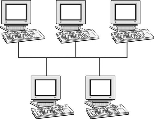
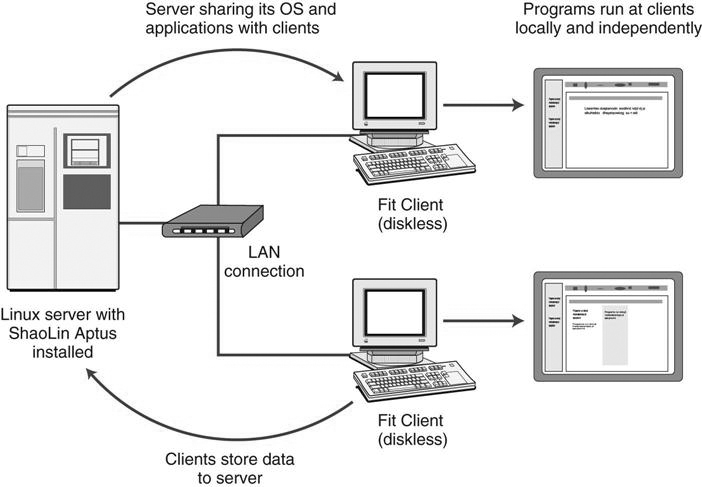
A local area network (LAN) (Figure 8-3) is a small area networked with a series of cables or wireless access points that allow computers to share information and devices on the same network. LANs are the least expensive to install, and they are much faster than WANs because of their smaller size. A LAN has the fastest communication technology because less equipment and fewer resources are needed to complete the network. Generally the larger networks are composed of several LANs interconnected to create the WAN. The picture archiving and communication system (PACS) workstations in a radiology reading room would be considered a LAN. The computers are interconnected and communicate by sharing images and reports.
Wide Area Network.
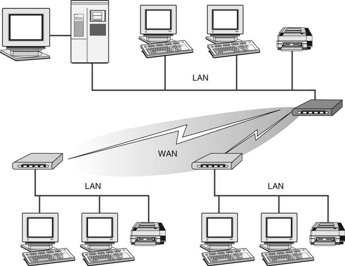
A wide area network (WAN) is a network that spans a large area: city, state, nation, continent, or the world (Figure 8-4) It is used to connect computers that are not physically attached through conventional network cables but are rather connected through other means, such as telephone lines, satellite links, or other types of communication cable. The use of these long distance communication links drives up the operating costs of this type of network because most often these communication links are owned by a separate company, and because of the distance covered, the cost of having the highest speed equipment is expensive.
Component Role Classification
Networks are typically classified as either peer-to-peer or server/client-based, depending on what role their various components play. The network is classified according to what role the computers play in the network’s operation and which computer controls the network operation.
Peer-to-Peer Network.
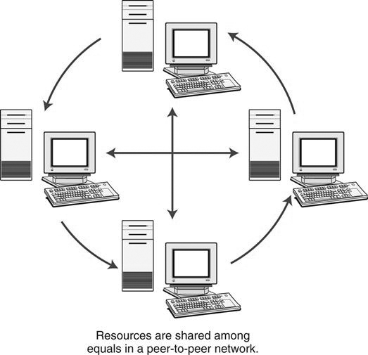
In a peer-to-peer network (Figure 8-5), each computer on the network is considered equal; no computer has ultimate control over another. Each computer controls its own information and operation and can function either as a client or as a server depending on the needs of the other computers on the network. The peer-to-peer network is the most popular small office or home network configuration because it is the least expensive and most simple to set up. However, a peer-to-peer network has a limited scope because the maximum number of peers that should be connected is 10. More than 10 peers causes bottlenecks and collisions on the network. An example of a peer-to-peer network is a small medical office with several computers connected to check in patients, verify insurance, produce bills for the service, and document patient history. A printer is shared among the group of computers.
Server-Based Network.
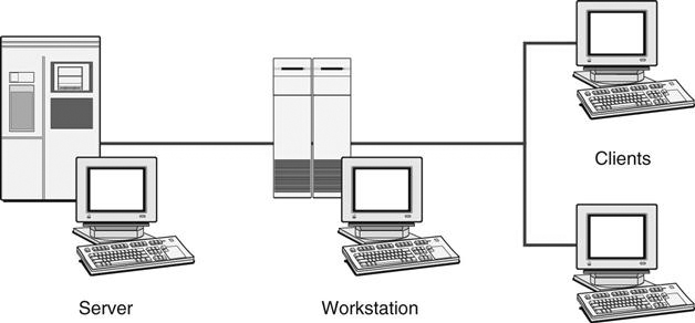
In a server-based network (Figure 8-6), there is a centralized computer (the server) that controls the operations, files, and sometimes the programs of the computers (the clients) attached to the network. The server provides a location for centralized storage and retrieval on the network. This allows the users to move from computer to computer and access their files from a central location. When a client requests a file, the server sends the entire file to the client for processing. Once the processing is completed, the client sends the entire changed file back to the server for storage. This type of network requires that the server be of high quality and high capacity, although the client computers can be less expensive.
There can be multiple servers on this type of network, but there must be one dedicated server that controls the network. An example of this type of network is a radiology department using a PACS to read and distribute images throughout the hospital. Computers throughout the hospital are connected to the centralized server that contains all of the images, and the images are sent out to the computers as requested.
Client-Based Network.
A client-based network is similar to a server-based network in that there is a centralized computer that controls the operations of the network; however, rather than sending the entire original resource to the client for processing, the server processes the resource as requested by the client and returns only the results back to the client. This smaller exchange of information lessens the load on the network and allows more room for other requests.
Typical Components of a Network
Computers
Typically there are three types of computers found on a network: server, thin client, and thick client (Figure 8-7). Each of the three has a specific purpose on the network.
A server is a computer that manages resources for other computers, servers, and networked devices. It may also house applications, provide storage for files, or manage various other networked tasks. A server is most often dedicated to one task for the network and is usually the most robust computer on the network. There may be one server that provides storage for files, one that manages the print functions, and another that provides Internet access for the network.
A thin client is a device that is found on a network that requests services and resources from a server. The thin client may be another computer, a printer, or any other networkable device that needs a server to complete its tasks. Almost any personal computer (PC) can be a client, as long as it can be attached to the network.
A thick client is a computer that can work independently of the network and process and manage its own files. The thick client is networked so that it can share resources such as printing and take advantage of the additional security available on networks through dedicated servers. A thick client is generally a high-end computer that does high-level processing for specific purposes. In health care, specialty application workstations (thick client) are most often found in sectional imaging modalities for which three-dimensional (3D) imaging is used to aid diagnosis. The sectional images are fed into the workstation’s application, and the application transforms the slices into a 3D image that can be evaluated.
Network Connectivity
Communication Medium.
Once it has been determined what files and resources are to be shared and the pieces of equipment are in place, the components are connected via some sort of communication medium. The connection between the devices is one of four types: coaxial cable, twisted-pair wire, fiber optic cable, or electromagnetic waves. Several factors determine which type of communication medium is most appropriate.
Coaxial cable (Figure 8-8) is similar to the wiring used for the cable television that is run into a house. This type of cable consists of a center conducting wire surrounded by insulation and then a grounded shield of braided wire. The shield minimizes electrical and radio frequency interference. Coaxial cable is the sturdiest wire used and is often found in the network infrastructure throughout a building. It is often connected to another type of communication medium before it meets the device interface.

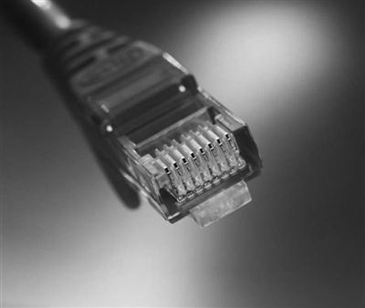
Twisted-pair wire (Figure 8-9) is similar to telephone wire, but whereas telephone wire has only four wires, twisted-pair wire usually consists of four twisted pairs of copper wires that are insulated and bundled together with an RJ-45 termination. Twisted-pair wire comes in various levels of quality and capacity. The minimum recommended standard is Cat 5 (category 5) cable. It is the most commonly used connection medium in LANs.
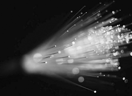
Fiber optic cable (Figure 8-10) uses glass threads to transmit data on the network. It consists of a fiber optic core that is surrounded by a plastic protective covering. This type of cable is much faster than its metal counterparts, but it is more expensive and much more fragile. Fiber optic cabling can easily be damaged by kinking and twisting the cable. It is most often used in the infrastructure of the network, in network closets, and in large archive/computer rooms.
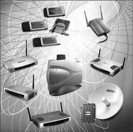
Wireless connections (Figure 8-11) are becoming more commonplace as technology continues to improve. The connection is made by using either infrared or radio frequencies as its means of communication. There is no physical cabling needed, but each device must contain the appropriate wireless transmitter/receiver. The biggest advantage of wireless connections is mobility and convenience, but these kinds of connections have a limited range. When using wireless access points as the means of connection, the thickness and composition of the wall and the distance from the source must be taken into account.
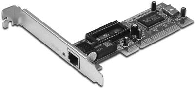
Network Interface Card.
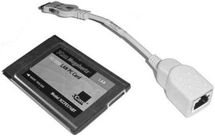
The network interface card (NIC) (Figure 8-12) provides the interface between the computer and the network medium; it provides the physical connection between the network and computer. The NIC works with networking software to establish and manage the data, to chop up the data into packets, and to handle addressing issues. Most NICs plug directly into the motherboard as an expansion card, but they can also come as small adapter cards that insert into a slot on the side of the portable computer (Figure 8-13).
Network Hub.
A network hub is the simplest device that can be used to connect several pieces of equipment together for network communication purposes. It has several wiring ports available on it to receive and transmit data to the various connected pieces of equipment. When the hub receives data from a device, it generally sends those data to all devices connected to it. The hub does not know what the data are, nor to which device they should go, so it simply forwards the bits. Hubs are commonly used in small office and home applications.
Network Switch.
A network switch is similar to a hub, but it sends data only to those devices to which the data are directed. It will read the destination address from the data and select a direct path to the intended target. This reduces the network traffic, speeds up the overall network connection, and makes the network more efficient. In general, switches are not commonly used in small office or home applications because there is not enough traffic to warrant the equipment.
Network Bridge.
A network bridge is sometimes created so that larger networks can be segmented or broken up into smaller networks to reduce traffic within that network. These segments can then be connected with a bridge. The bridge is a physical (wired) connection from one network segment to another. It can recognize in which segment a particular destination address resides and send data to it. The bridge can also bring two or more networks together that speak the same language (i.e., use the same protocol).
Network Router.
A network router is a more sophisticated device. It can read portions of messages and direct them to their intended target, even if the device is on a separate network and uses a different network protocol. It also helps with segmenting the network to allow access only for approved devices within that segment. In large networks there will be multiple routers, switches, and hubs that work in concert to perform the necessary tasks that enable the network to perform up to its potential.
Network Communication
We have learned that devices communicate via a NIC through some sort of communication medium. We know that the data are sent through some sort of box and that the box reads the destination address in the data to send them to the appropriate target. The question now is, Where does the address come from?
Each computer on the network is assigned a unique address. The address is a combination of a physical address from the computer’s hardware and a node address given by the network. One type of addressing is Internet protocol (IP) addressing, which is made up of four octets (groups of 8 bits) of numbers. The numbers range from 0 to 255 (e.g., 144.162.21.107). The first set of numbers indicates the network class, and the rest of the numbers tell other devices the network’s exact location. When a message is sent, the computer’s NIC will read the destination address and check to see whether it matches the computer’s network address. If it matches, it will receive the message. If it does not match, it just ignores the message.
The data travel along the network using an agreed-on set of rules known as a network protocol. Most network protocols send data in packets from one device to another. A packet is a piece of the data with added information, such as the destination address, the source address, the sequence of the packets (e.g., 2 of 12), and whether there were any errors in transmission. The protocol is delivered in layers of communication known as protocol stacks. Each layer of the communication represents a particular aspect of network functionality.
Typically a network communication model is explained using seven layers (OSI Model). We need to understand only the basic principles of network communication, so we will simplify the model and concentrate on the bottom four layers.
The most important thing to understand is that because of this standardized model, different types of networkable machines can be connected to transmit data to each other. As long as the machines share the same low-level protocols or know how to convert from one into another, the packets can be received and reconstructed.
Network Topology
Topology is the physical (geometric) layout of the connected devices on a network. There are four common topology configurations: bus, ring, star, and mesh. Many things should be considered when deciding what type of topology should be used, such as the type of communication media, the network speed, the connecting equipment design, and the number of devices to be connected. Each of these four is discussed in the following sections.
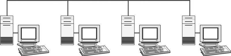
Bus
A bus topology (Figure 8-14) is a network in which all devices are physically attached to and listen for communication on a single wire. In a true bus network there is a single point of failure, the wire. If at some point on the wire there is a break, the entire network is down. (In some circumstances communication can take place between the computers on either side of the break.) This type of topology does not need any switches or hubs because the computers simply broadcast all the information down the single wire, and all computers connected to that single wire receive the information.
Ring
A ring topology (Figure 8-15) is a network in which the devices are connected in a circle. Each device passes its received messages to the next node on the ring (always in the same direction), and the data transmissions move around the circle until they reach the correct receiver. If there is a break at some point in the ring, the entire network comes to a halt.
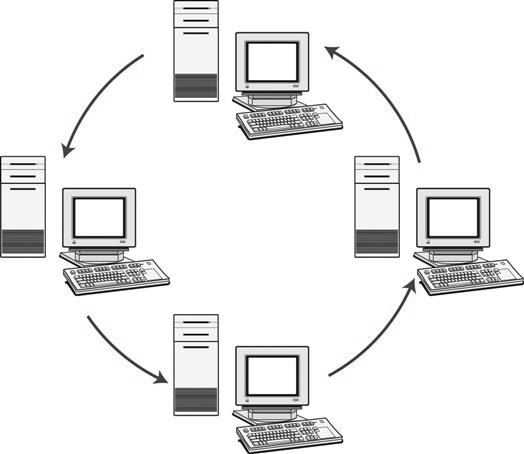
One type of ring topology is called a token ring. The computers are connected in a circle, and a token is transmitted around the ring. When a computer is ready to send a transmission to another computer, it picks up the empty token as it passes by and fills it with the message. As the token passes the other computers, the destination address is read by each passing computer and is ignored if the address does not belong to that computer. When the addressed computer is found, the data are deposited, and the token is now free again. If another computer wishes to send out information but the token is occupied, it must wait until the token becomes free again before it can transmit.
Star
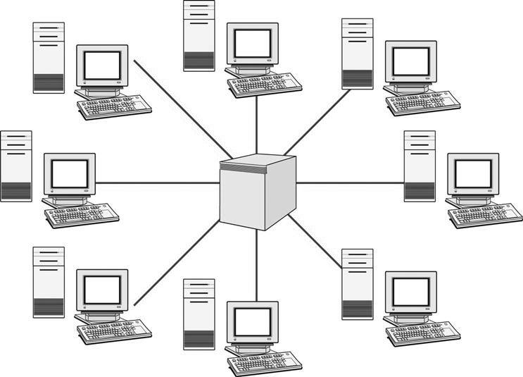
A star topology (Figure 8-16) is a network that has the devices connected to a central hub or switch. A star topology can be thought of as a bus topology with the bus collapsed into a central box: the hub or switch. The data are sent through the hub out to the destination device. This transmission of data may be through another hub or switch to an adjacent network or directly to the device. Star topology is the most commonly used network topology.
Mesh
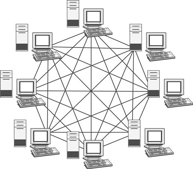
A mesh topology (Figure 8-17) is a network that has multiple pathways interconnecting devices and networks. This type of network has redundancy built in with the multiple connections. The Internet is based on mesh topology, and this topology is used most often to connect networks to other networks.
Application Interfacing
DICOM
DICOM, which stands for digital imaging and communications in medicine, has become an almost universally accepted standard for exchanging medical images among networked medical devices. DICOM is layered on top of TCP/IP, the most common network communication standard used, and it has multiple layers as does TCP/IP.
DICOM was developed by the American College of Radiology (ACR) and the National Electrical Manufacturers Association (NEMA). The first version was completed in 1985, addressing only point-to-point connections between devices. At publication of this book, the current version is 3-2011. (There are revisions and additions always in progress.) Up-to-date information can be found on NEMA’s website at http://medical.nema.org.
DICOM (3.0) is better than its predecessors for several reasons:
The DICOM standard is made up of 20 different parts ranging from image display to media storage. Not every device conforms to every part of the DICOM, but rather a device will conform to the parts that are necessary to perform the tasks it is assigned according to what is desired by the user. The standard is maintained on a continuous basis and is published periodically. Supplements are published with new updates and error corrections, and new parts are being investigated as new functions are developed. Table 8-1 lists the 20 parts of the DICOM standard and their corresponding titles.
TABLE 8-1
The 20 Parts of the DICOM Standard 3-2011
| PS 3.1 | Introduction and overview |
| PS 3.2 | Conformance |
| PS 3.3 | Information object definitions |
| PS 3.4 | Service class specifications |
| PS 3.5 | Data structures and encoding |
| PS 3.6 | Data dictionary |
| PS 3.7 | Message exchange |
| PS 3.8 | Network communication support for message exchange |
| PS 3.9 | Retired |
| PS 3.10 | Media storage and file format for media interchange |
| PS 3.11 | Media storage application profiles |
| PS 3.12 | Media formats and physical media for media interchange |
| PS 3.13 | Retired |
| PS 3.14 | Grayscale standard display function |
| PS 3.15 | Security and system management profiles |
| PS 3.16 | Content mapping resource |
| PS 3.17 | Explanatory information |
| PS 3.18 | Web access to DICOM-persistent objects (WADO) |
| PS 3.19 | Application hosting |
| PS 3.20 | Transformation of DICOM to and from HL-7 Standards |
DICOM, Digital imaging and communications in medicine; HL-7, Health Level 7.
The DICOM standard defines so-called service classes or functions that a device can perform on a defined information object (such as a CT image). The allowed service/object pairs (SOPs) for a device are spelled out explicitly in the device’s DICOM conformance statement. A device performs either as a service class user (SCU) for a given service and object or as a service class provider (SCP) or as both. The SCU and SCP are commonly referred to as roles. Network communications (i.e., transactions) in DICOM are always between an SCP and an SCU. The following are the most common service classes seen in modalities and PACS:
Each of these services defines a specific transaction for the modality and PACS, and because of the standardization provided by DICOM, device interoperability is possible (or at least more likely). The DICOM conformance statement of a device details the various SOPs and possible roles that the modality or workstation can fulfill with those SOPs. For example, if a magnetic resonance imaging (MRI) scanner conformance statement lists the MRI storage SOP class in the SCU role, and the receiving PACS archive lists MRI storage SOP class in the SCP role, the MRI scanner would be able to send images to the archive based on those statements. If either statement does not support the proper SOP class and role, the transfer is not possible. Most modalities manufactured today are DICOM conformant. The vendors will provide conformance statements, and the buyer must closely inspect these statements to ensure that the modalities can communicate with existing image viewing devices.
DICOM also has specifications for uniquely identifying each study, series, and image (instance). DICOM uses unique identifiers (UIDs) to globally identify each image set, so that if the images are sent to multiple systems, the identifying number will remain unique and not be confused with those images on other systems. Each study is identified by a study instance UID, which breaks down into series instance UIDs, and further into instance UIDs. The numbers are created based on a vendor number, serial number of the equipment, date, time, patient or processing number, and then the study, series, or image number. A typical study instance UID may look like this: 1.2.840.8573.4567.1.20051011764589.8765.1.
DICOM also provides a framework for the use of compression technologies on image data. For example, DICOM accommodates joint photographic experts group (JPEG) lossless compression of 2 to 1. This is the most common compression technique used within hospitals because there is no image degradation on viewing after decompression. But when moving images outside of the hospital, it may be necessary to use lossy compression to shrink the file size to suit external networks. Some loss of image detail can occur when higher compression values are used.
When a patient arrives for a procedure, the technologist either has to manually type in the patient’s demographics, risking error, or alternatively pull the information directly from the radiology information system (RIS). A modality can pull this information when it supports the service class of modality worklist management, and the RIS can either interface via DICOM or through a gateway that creates an interface with the Health Level 7 (HL-7) device and the DICOM device.
After an image has been captured, all of the demographic information and information about the actual capture of the image is recorded in the image header. The DICOM image header contains many different elements, such as the patient name, ID, referring physician, the number of images in the study, and it can also contain the actual technical factors used for the capture. In digital projection radiography, the kilovoltage peak (kVp), milliampere-seconds (mAs), and the exposure indices are captured on all but cassette-based storage phosphor systems. The technologist must realize that any manipulation of an image will be recorded in this header and he or she is held legally responsible for any image manipulation that occurs.
HL-7
HL-7 is an American National Standards Institute (ANSI)–accredited Standards Developing Organization (SDO).
The standards set by this organization are used in most health care applications such as medical devices, imaging, insurance, and pharmacy. The HL-7 standards oversee most clinical and administrative data such as demographics, reports, claims, and orders. As with DICOM, HL-7 is composed of many parts and is used at many levels within various hospital systems. HL-7 standards are generally used in communication between the hospital information system (HIS) and the radiology information system (RIS). The HIS holds the patient’s full medical information, from hospital billing to the inpatient ordering system. The RIS holds all radiology-specific patient data, from the patient scheduling information to the radiologist’s dictated and transcribed report. The electronic medical record (EMR) has recently come to the forefront of information technology. The EMR is either a part of the HIS or runs along with it and contains all of the patient’s record, including lab results, radiology reports, pathology results, and nurses’ and doctors’ notes. The EMR interfaces with most of the ancillary service systems to retrieve reports so that they can be viewed in this one common format. PACS have also begun interfacing with EMRs to present images to referring physicians through the same common system.
Summary
[/level-membership-for-radiology-category][not-level-membership-for-radiology-category]
Networking and Communication Basics
Objectives
On completion of this chapter, you should be able to:
• Distinguish between different types of networks (geographic and component roles).
• Identify common network hardware components.
• Describe different types of network cabling and their uses.
• Differentiate between the common network topologies.
• Discuss the use of digital imaging and communications in medicine (DICOM) in medical imaging.
• Define HL-7, and describe its use in health care information systems.
Key Terms
Bus topology
Client-based network
Coaxial cable
Digital imaging and communications in medicine (DICOM)
Fiber optic cable
HL-7
Hospital information system (HIS)
Local area network (LAN)
Mesh topology
Network
Network bridge
Network hub
Network interface card (NIC)
Network protocol
Network router
Network switch
Peer-to-peer network
Radiology information system (RIS)
Ring topology
Server
Server-based network
Star topology
Thick client
Thin client
Topology
Twisted-pair wire
Wide area network (WAN)
Wireless
Wireless access point
People use all types of networks every day to do things such as check the status of a package being shipped or register for a class at school. Many daily tasks involve transferring information, either from person to person (Figure 8-1) or from computer to computer (Figure 8-2).
A computer network is defined as (1) two or more objects sharing resources and information, or (2) computers, terminals, and servers that are interconnected by communication channels sharing data and program resources. Devices other than computers can also be found on a network, such as printers, scanners, and barcode readers. These devices can be shared among a group of computers to save money and space for the users.
This chapter explores network classifications, whether they are based on geographic boundaries or on the various roles that the hardware components play. An overview of the basic hardware components that make up a computer network and how the networks are physically constructed is also included. This chapter also provides a brief introduction to how medical devices, such as computed tomography (CT) scanners and computed radiography (CR) readers, fit within a network and how they communicate.
Network Classifications
Geographic Classifications
A network can be classified into two major geographic categories: local area network (LAN) and wide area network (WAN). (Other geographic classifications exist, such as metropolitan area network (MAN), tiny area network (TAN), and controller area network (CAN), but these are of little consequence to radiology.) These two terms are fairly self-explanatory: a LAN is close by, whereas a WAN expands over a distance.
Local Area Network.
A local area network (LAN) (Figure 8-3) is a small area networked with a series of cables or wireless access points that allow computers to share information and devices on the same network. LANs are the least expensive to install, and they are much faster than WANs because of their smaller size. A LAN has the fastest communication technology because less equipment and fewer resources are needed to complete the network. Generally the larger networks are composed of several LANs interconnected to create the WAN. The picture archiving and communication system (PACS) workstations in a radiology reading room would be considered a LAN. The computers are interconnected and communicate by sharing images and reports.
Wide Area Network.
A wide area network (WAN) is a network that spans a large area: city, state, nation, continent, or the world (Figure 8-4) It is used to connect computers that are not physically attached through conventional network cables but are rather connected through other means, such as telephone lines, satellite links, or other types of communication cable. The use of these long distance communication links drives up the operating costs of this type of network because most often these communication links are owned by a separate company, and because of the distance covered, the cost of having the highest speed equipment is expensive.
Component Role Classification
Networks are typically classified as either peer-to-peer or server/client-based, depending on what role their various components play. The network is classified according to what role the computers play in the network’s operation and which computer controls the network operation.
Peer-to-Peer Network.
In a peer-to-peer network (Figure 8-5), each computer on the network is considered equal; no computer has ultimate control over another. Each computer controls its own information and operation and can function either as a client or as a server depending on the needs of the other computers on the network. The peer-to-peer network is the most popular small office or home network configuration because it is the least expensive and most simple to set up. However, a peer-to-peer network has a limited scope because the maximum number of peers that should be connected is 10. More than 10 peers causes bottlenecks and collisions on the network. An example of a peer-to-peer network is a small medical office with several computers connected to check in patients, verify insurance, produce bills for the service, and document patient history. A printer is shared among the group of computers.
Server-Based Network.
In a server-based network (Figure 8-6), there is a centralized computer (the server) that controls the operations, files, and sometimes the programs of the computers (the clients) attached to the network. The server provides a location for centralized storage and retrieval on the network. This allows the users to move from computer to computer and access their files from a central location. When a client requests a file, the server sends the entire file to the client for processing. Once the processing is completed, the client sends the entire changed file back to the server for storage. This type of network requires that the server be of high quality and high capacity, although the client computers can be less expensive.
There can be multiple servers on this type of network, but there must be one dedicated server that controls the network. An example of this type of network is a radiology department using a PACS to read and distribute images throughout the hospital. Computers throughout the hospital are connected to the centralized server that contains all of the images, and the images are sent out to the computers as requested.
Client-Based Network.
A client-based network is similar to a server-based network in that there is a centralized computer that controls the operations of the network; however, rather than sending the entire original resource to the client for processing, the server processes the resource as requested by the client and returns only the results back to the client. This smaller exchange of information lessens the load on the network and allows more room for other requests.
Typical Components of a Network
Computers
Typically there are three types of computers found on a network: server, thin client, and thick client (Figure 8-7). Each of the three has a specific purpose on the network.
A server is a computer that manages resources for other computers, servers, and networked devices. It may also house applications, provide storage for files, or manage various other networked tasks. A server is most often dedicated to one task for the network and is usually the most robust computer on the network. There may be one server that provides storage for files, one that manages the print functions, and another that provides Internet access for the network.
A thin client is a device that is found on a network that requests services and resources from a server. The thin client may be another computer, a printer, or any other networkable device that needs a server to complete its tasks. Almost any personal computer (PC) can be a client, as long as it can be attached to the network.
A thick client is a computer that can work independently of the network and process and manage its own files. The thick client is networked so that it can share resources such as printing and take advantage of the additional security available on networks through dedicated servers. A thick client is generally a high-end computer that does high-level processing for specific purposes. In health care, specialty application workstations (thick client) are most often found in sectional imaging modalities for which three-dimensional (3D) imaging is used to aid diagnosis. The sectional images are fed into the workstation’s application, and the application transforms the slices into a 3D image that can be evaluated.
Network Connectivity
Communication Medium.
[/not-level-membership-for-radiology-category]
