[level-membership-for-orthopaedics-category]
CHAPTER 58 Minimally Invasive Posterior Lumbar Fusion Techniques
Despite these advances, the morbidity of spinal fusion surgery remains significant. The standard posterior midline exposure is notorious for paraspinal muscle stripping and denervation leading to significant postoperative scar formation. The limitations of this approach for spinal fusion have been well documented, especially regarding a prolonged recovery period and muscle damage that may affect a patient following surgery.1–5
In recent years, less invasive surgical approaches have been developed to minimize damage to the paraspinal soft tissues during surgical exposure. These “minimally invasive” surgical approaches are becoming more popular because they offer the surgeon a method to achieve the goals of spinal surgery while minimizing some of the perioperative morbidity inherent to the classic posterior approach.6,7
Principles of Minimally Invasive Spinal Surgery
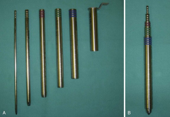
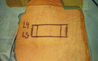
All minimally invasive spinal procedures, despite the type and the location, have the common goal of correcting the underlying spinal pathology while avoiding excessive damage to the paraspinal soft tissue envelope. As with other spine procedures, an MISS procedure begins with the careful analysis of the preoperative imaging studies to precisely localize the spinal pathology. Before making a surgical incision, preoperative fluoroscopy is used to localize the involved spinal segments and plan the skin incision. During the surgical approach, the paraspinal muscles are split rather than cut or resected using serial tubular dilators to create a surgical corridor between the skin incision and the spine (Fig. 58–1). Only necessary portions of the vertebral columns are exposed, and excessive use of electrocautery or vigorous retractor pressures should be avoided.
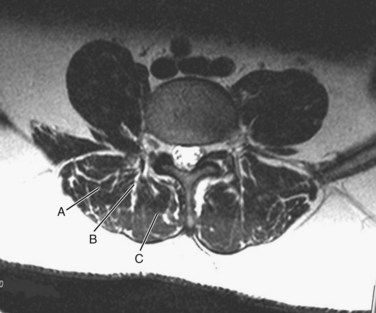
The surgeon must understand the muscular anatomy of the paraspinal region to design the optimal approach for an MISS procedure. There are two distinct muscular compartments: the multifidus compartment, which overlies the midline spinal structures, and the lateral compartment, which overlies the transverse processes (Fig. 58–2). The multifidus muscle surrounds the spinous processes, lamina, and facet joints. The multifidus muscles receive its nerve and blood supply from the medial branches of the dorsal rami and segmental vessels, respectively, which course from the intervertebral foramen along the base of the transverse process and enter the lateral margin of the muscle in the region of the pars intra-articularis. Care should be taken to avoid rupturing the lateral attachments of the multifidus muscle, which would disrupt the nerve and blood supply to the multifidus muscle, leading to atrophy and scar formation in the substance of the muscle. The lateral muscle compartment contains the longitudinally oriented muscles of the erector spinae group. The lateral compartment overlies the transverse processes and includes the entry site for pedicle screw insertion at the base of the transverse process. The lateral compartment is traversed whenever a posterolateral onlay fusion is performed.
Surgical Setup for a Posterior Fusion Procedure
Setup and Imaging
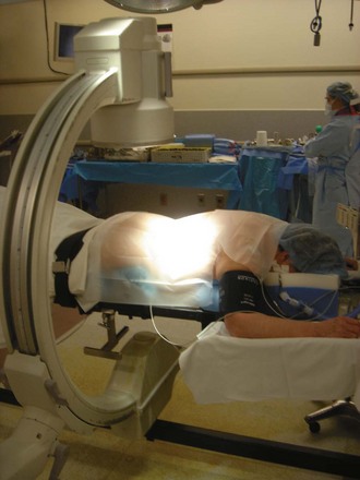
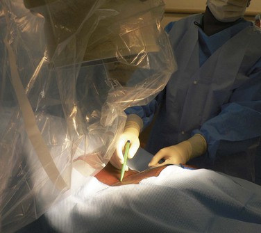
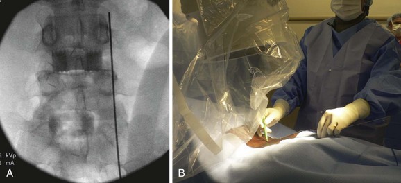
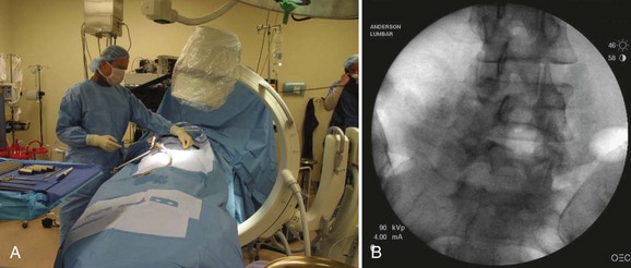
Following placement of surgical monitoring equipment and the induction of general anesthesia, the patient should be positioned prone on a radiolucent spinal frame (Fig. 58–3). The abdomen should be free of compression, and free access to the lumbar region for fluoroscopy should be confirmed. The preoperative imaging studies should be available in the room with the operative plan clearly marked. The surgeon should ensure the availability of the proper implants and instruments prior to commencing with the operative procedure.
Surgical Incisions and Approach
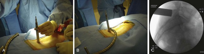
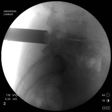
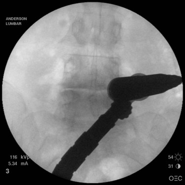
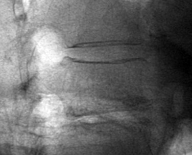
When operating through a tubular retractor, the smallest dilator is then docked at the appropriate bony site and serial dilation is used to expand the operative corridor. Care should be taken into bringing each subsequent dilator in contact with the bony elements. The correct length of the tubular retractor can then be selected, inserted, and secured using an operating table–mounted retractor holder. Once the tubular retractor is in place, the position of the retractor should be verified using fluoroscopy (Fig. 58–4).
Posterior Interbody and Transforaminal Interbody Fusion
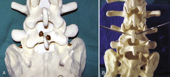
When performing a posterior or transforaminal lumbar interbody fusion (PLIF and TLIF) via a minimally invasive approach, it is important to align the tubular retractor collinear with the disc space on the lateral view (Fig. 58–5). When performing a TLIF procedure, the tubular retractor must be aligned with enough lateral to medial angulation to allow the surgeon to reach the contralateral side of the disc space for preparation of an adequate fusion bed (Fig. 58–6). During the exposure, adequate facet joint must be removed to minimize retraction of the neural elements and provide working access to the disc space.8
The detrimental effects of over-retraction of the neural elements with the PLIF procedure have been well documented in the literature.9 Facet removals for a PLIF or TLIF can be achieved with either osteotomes or a high-speed burr. It is helpful to skeletonize the upper and medial portions of the caudal pedicle (e.g., L5 pedicle for a L4-5 TLIF) to gain adequate access to the disc space and allow safe retraction/protection of the dural/neural elements.
After disc space preparation, the interspace should be packed with autogenous bone graft or an adequate fusion substrate. An interbody fusion cage, of appropriate size, is selected and packed with the graft material, before impacting the cage into the disc space. The optimal position of the cage is toward the anterior portion of the disc space.10,11 This produces better reconstruction of the sagittal contour of the spine and allows ample bone graft material to be packed around and behind the cage.
Posterolateral Fusion (Intertransverse Onlay Fusion)
From the traditional midline approach, access to the intertransverse region for onlay fusion requires complete stripping of the paraspinal muscles to the tips of the transverse processes, an act that causes destruction, or at least disruption, of the multifidus muscle and significant postoperative scarring.5 Using the paraspinal muscle-splitting approach (Wiltse approach), exposure of the intertransverse region is simple to achieve without major muscle stripping. This provides direct access to the intertransverse region for fusion.
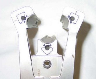
The skin incision for a paraspinal approach for intertransverse fusion is made at least 3.5 to 4 cm lateral to the midline. The fascia is divided in line with the skin incision, and the paraspinal muscles are split in line with their fibers to expose the transverse processes. For fusion purposes, the entire transverse process at both levels should be exposed. Either a tubular retractor (preferably an expandable tubular retractor) or side-to-side (e.g., McCullough retractor) retractor can be used to visualize the intertransverse interval. The authors prefer to use an expandable tubular retractor, which allows both transverse processes to be simultaneously exposed (Fig. 58–7).
Facet Fusion
To perform a facet fusion, the retractor should be docked on the facet, which resides in the lateral portion of the multifidus compartment (see Fig. 58–2). If decompression of the spinal canal is required, facet fusion can easily be performed during the exposure through the multifidus compartment. Once the facet is exposed, the capsule is removed with electrocautery and the articular surfaces of the inferior and superior articular processes are identified. A high-speed burr is used to decorticate the facet joint along its entire length, and the joint space is packed with fragments of autogenous bone or a suitable bone substitute.
Instrumentation of the Spine
Pedicle Screw Instrumentation
Pedicle screw instrumentation has emerged as the most common form of internal fixation used for thoracolumbar arthrodesis. Pedicle screws offer numerous advantages compared with hooks or wires, which are less rigid. Pedicle screws can be used when posterior spinal elements are deficient due to prior surgery, and they provide rigid segmental immobilization, thereby minimizing the need for postoperative brace immobilization. Because of the three-column support provided by the transpedicular fixation, these implants are effectively used in various complex spinal pathologies including deformities, which require corrective forces to be employed.12
Cannulated Pedicle Screw Insertion
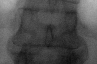
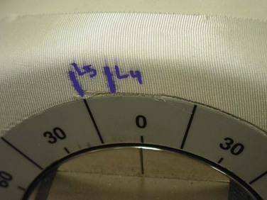
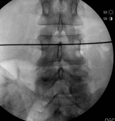
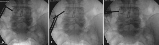
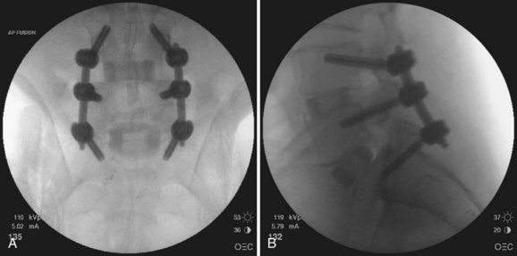
The first step in placing cannulated pedicle screws involves obtaining a true AP image of each vertebra to be instrumented (Fig. 58–8). Because of the natural sagittal contour of the spine, the C-arm must be angulated to the specific sagittal profile of each individual vertebra in order to obtain the true AP view. It is helpful to have the radiology technician mark the exact angle of the C-arm where the true AP image can be obtained to assist rapid return to the proper image (Fig. 58–9). A properly aligned AP C-arm image will demonstrate the superior vertebral endplate as a single, dense line, and the pedicles will be localized just below the upper endplate. Correct rotation of the vertebrae is ensured when the spinous process shadow is centered between the pedicles. The true AP view is most useful when cannulating the pedicle during pedicle screw insertion.
True lateral fluoroscopic images are also used during pedicle screw instrumentation, particularly during assembly of the construct (Fig. 58–10). The true lateral image will demonstrate the superior endplate as a single, dense line. The pedicles will be superimposed. The posterior cortex of the vertebral body should also appear to be a single radiopaque line, confirming that no rotation of the vertebra is present. The true lateral view is useful during pedicle tapping, placement of pedicle screws, and assembly of the construct. In cases where scoliosis is present, the C-arm may need to be angled (i.e., “wig-waged”) to obtain a true lateral view of each vertebra.
After obtaining a true AP fluoroscopic image of a given level, a K-wire should be aligned over the skin of the back so that it appears to bisect the pedicles (Fig. 58–11). Next, a horizontal line is drawn along the skin using the K-wire (Fig. 58–12). This step should be repeated using a true AP image for each of the vertebrae in the construct. Vertical lines are then drawn (using a K-wire placed over the skin of the back) along the lateral pedicle shadow (Fig. 58–13). Skin incisions for percutaneous pedicle screw insertion should be placed about 1 cm lateral to the vertical line (Fig. 58–14).
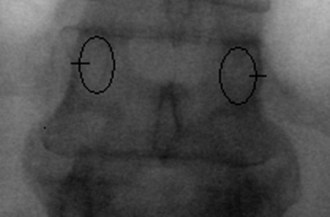
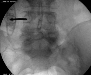
Once the skin and fascia have been divided, the surgeon can digitally palpate the transverse process of the vertebra whose pedicles are to be cannulated. A Jamshidi needle is then placed at the base of the transverse process (at the junction of the transverse process and superior articular process), and a true AP image is obtained (Fig. 58–15). The goal is to position the tip of the needle directly over the lateral margin of the pedicle shadow (at the 3 o’clock and 9 o’clock positions) on the true AP view (Fig. 58–16). The tip of the needle should be adjusted until the tip of the needle lies directly at the lateral boarder of the pedicle. The needle shaft is then aligned parallel to the endplate (or transverse process) on the AP image, which ensures a needle trajectory parallel to central axis of the pedicle (Fig. 58–17). The shaft of the needle should also be held with a lateral to medial trajectory of approximately 10 to 15 degrees, depending on the level to approximate the normal divergence of the pedicles anatomically. Then, the needle is tapped gently a few times to seat the needle tip into the bone and ensure that slippage of the needle tip does not occur as the needle is driven through the pedicle. A final true AP image is checked to be sure that the needle is properly positioned and aligned.
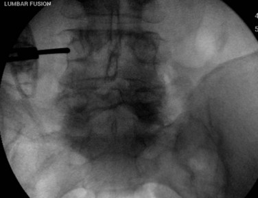
FIGURE 58–15 The Jamshidi needle is placed, with fluoroscopic assistance, at the base of the transverse process.
Next, a line is drawn on the shaft of the Jamshidi needle, 20 mm above the skin edge (Fig. 58–18). Because the average length of the pedicle is 20 mm from the starting point, this line is used to determine the depth of the needle tip as it is driven through the pedicle. With the Jamshidi needle properly aligned, the needle is tapped with a mallet to drive the needle through the bone of the central pedicle. When this line on the needle shaft reaches the skin edge, the needle tip has traversed the pedicle isthmus and is at approximately the depth of the base of the pedicle. At this point another true AP fluoroscopic image is obtained to ensure that the needle tip lies well within the pedicle shadow, no more than three fourths of the distance (from lateral to medial) across the pedicle (Fig. 58–19). This true AP image should be critically analyzed, and if the needle tip is in proper position, then it is deemed acceptable for pedicle screw insertion.
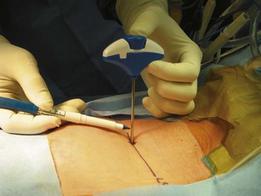
FIGURE 58–18 The Jamshidi needle is marked 20 mm above the skin edge, an estimate of the depth of the pedicle.
Once all of the pedicles in the construct have been cannulated and guidewires have been placed, the C-arm is adjusted to obtain true lateral images of the spine (Fig. 58–20). The position of the guidewires on the lateral fluoroscopic view is verified before proceeding with pedicle preparation. Pedicle preparation and pedicle screws placement are then carried starting from one end of the construct in an “assembly line” fashion. Each pedicle is tapped using a cannulated tap. The authors prefer to stimulate the tap using stimulus-evoked EMG to ensure no low voltage activity is present. If so, it might indicate a breech of the pedicle. Then cannulated pedicle screws are placed over the guidewires at each level and threaded into the pedicles. The pedicle screws are adjusted in height as needed to maintain polyaxial motion of the screw crowns and to achieve a smooth contour of the screws at adjacent levels (necessary for rod seating). It is also the author’s preference to stimulate each pedicle screw, after insertion with stimulus-evoked EMG, using an insulated port over the screws (Fig. 58–21).
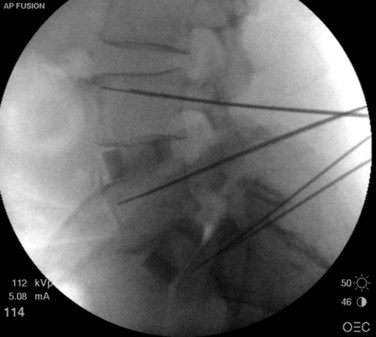
FIGURE 58–20 True lateral fluoroscopic image showing the guidewires properly placed within the pedicles.
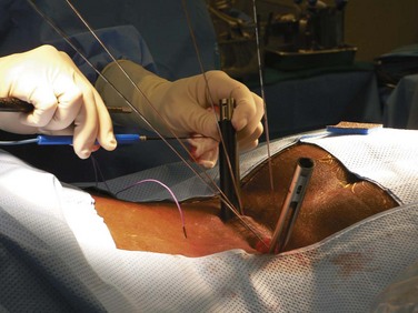
FIGURE 58–21 Following their insertion, pedicle screws are tested with stimulus-evoked electromyography, using an insulated port.
Once are the screws are positioned, the proper rod length is measured and rods are inserted through the screw extensions and into the screw crowns. The details of rod insertion differ slightly among manufacturers of cannulated screw systems. The surgeon should be familiar with the details of the specific system selected. After the rods are placed, screw caps are inserted into each screw to capture the rod. Compression or distraction of the construct can be performed as needed, followed by final tightening of the construct. At the conclusion of the procedure, AP and lateral imaging of the entire construct should be obtained (Fig. 58–22).
Technical Tips
A few technical points are worth mentioning. First, the advancement of the Jamshidi needle across the pedicle should proceed smoothly with light to moderate taps of the mallet. If the surgeon encounters very hard bone, it generally indicates that the needle tip is displaced medially into the facet joint (the needle tip is striking the hard cortical surface of the superior articular facet). In this instance, the surgeon should withdraw the needle tip and begin with a slightly more lateral starting point to prevent the needle tip from slipping into the facet joint. Another useful tip is to consider the en face view if the AP view fails to clearly show the outline of the pedicle (this is most commonly a concern at the L5 level). To obtain an en face view, start with a true AP view and then angulate the C-arm 10 to 15 degrees in the axial plane to line up the beam with the pedicle axis (Fig. 58–23). Using the en face view, the center of the pedicle should be targeted, keeping the shaft of the needle in line with the C-arm beam. Another useful tip concerns making minor adjustments to a cannulated pedicle screw trajectory. In such a case, the pedicle can be tapped (with a cannulated tap) to the base of the pedicle and then, leaving the tap in place, the guidewire can be withdrawn into the tap, allowing the trajectory of the tap to be adjusted as desired with the assistance of fluoroscopy. Once the new trajectory is achieved, the guidewire is reinserted into the vertebral body along the new trajectory. Finally, stimulus-evoked EMG testing of the taps and screws has proven to be a useful adjuvant to the placement of percutaneous pedicle screws. Any low voltage activity (<8 mV) should alert the surgeon to pursue additional measures to ensure correct placement of the implant.
Facet Screw Instrumentation
Although pedicle screws are the “work horse” for most spinal fixation strategies, facet screws offer certain advantages in selected cases. Facet screws are quick and relatively easy to place. They are generally less expensive, compared with pedicle screw implants, and yet offer comparable initial stiffness for short constructs.13 In certain clinical situations such as following anterior lumbar interbody fusion, facet screw instrumentation has been shown to produce favorable clinical results.14,15
Benini and Magerl16 described a technique using large-fragment (4.5-mm) cortical bone screws to perform a translaminar fixation of the facet joint. The screw path begins at the base of the spinous process on one side and is then advanced across the contralateral lamina and facet joint (Fig. 58–24). Two screws are placed to immobilize the facet joints bilaterally using a miniopen or percutaneous technique.17,18
Next, a line connecting the midfacet (or medial boarder of the pedicle) and the pilot hole is marked on the skin. This trajectory can be extended superiorly and laterally to the midline incision. A small, percutaneous incision is made along this line, about 10 to 12 cm from the midline such that the drill trajectory will be in line with the contralateral lamina. A drill guide is inserted into the percutaneous incision and advanced into the midline exposure (Fig. 58–25). The drill is inserted and seated into the pilot hole at the base of the spinous process. The drill is adjusted as needed so that the drill will traverse the lamina and then facet joint. As the drill is advanced, the surgeon should feel uniform resistance until the facet joint has been breeched. A momentary change in resistance may be noted as the facet joint space is traversed, but the cortical bone of the superior articular process will then be encountered. After drilling, the length of the screw path is measured. Then, a 4.5-mm, fully threaded cortical screw is placed to secure the position of the facet joint. A similar, percutaneous technique has been described, relying only on fluoroscopic images to ensure adequate placement of the translaminar facet screw implants.15
Patient Selection
Patient selection remains the most crucial outcome variable for any spinal procedure.19 The same selection criteria that have been shown to produce success in traditional spinal surgery apply to patient selection for an MISS approach. In addition, patients being considered for an MISS approach have some additional selection criteria that should be considered.20
Conclusion
Pearls
Pitfalls
Key Points
1 Benglis DM, Elhammady MS, Levi AD, et al. Minimally invasive anterolateral approaches for the treatment of back pain and adult degenerative deformity. Neurosurgery. 2008;63:191-196.
2 Kwon BK, Berta S, Daffner SD, et al. Radiographic analysis of transforaminal lumbar interbody fusion for the treatment of adult isthmic spondylolisthesis. J.Spinal Disord.Tech.. 2003;16:469-476.
3 Liljenqvist U, Lepsien U, Hackenberg L, et al. Comparative analysis of pedicle screw and hook instrumentation in posterior correction and fusion of idiopathic thoracic scoliosis. Eur Spine J. 2002;11:336-343.
4 Parker LM, Murrell SE, Boden SD, et al. The outcome of posterolateral fusion in highly selected patients with discogenic low back pain. Spine. 1996;21:1909-1916.
5 German JW, Adamo MA, Hoppenot RG, et al. Perioperative results following lumbar discectomy: comparison of minimally invasive discectomy and standard microdiscectomy. Neurosurg Focus. 2008;25:E20.
1 Fritzell P, Hagg O, Nordwall A. Complications in lumbar fusion surgery for chronic low back pain: comparison of three surgical techniques used in a prospective randomized study. A report from the Swedish Lumbar Spine Study Group. Eur Spine J. 2003;12:178-189.
2 Katz JN. Lumbar spinal fusion. Surgical rates, costs, and complications. Spine. 1995;20(24 Suppl):78S-83S.
3 Malter D, McNeney B, Loeser JD, et al. 5-year reoperation rates after different types of lumbar spine surgery. Spine. 1998;23:814-820.
4 Stauffer RN, Coventry MB. Posterolateral lumbar-spine fusion. Analysis of Mayo Clinic series. J Bone Joint Surg Am. 1972;54:1195-1204.
5 Motosuneya T, Asazuma T, Tsuji T, et al. Postoperative change of the cross-sectional area of back musculature after 5 surgical procedures as assessed by magnetic resonance imaging. J Spinal Disord Tech. 2006;19:318-322.
6 Foley KT, Holly LT, Schwender JD. Minimally invasive lumbar fusion. Spine. 2003;28(15 Suppl):S26-S35.
7 Benglis DM, Elhammady MS, Levi AD, et al. Minimally invasive anterolateral approaches for the treatment of back pain and adult degenerative deformity. Neurosurgery. 2008;63:191-196.
8 Kasis AG, Marshman LA, Krishna M, et al. Significantly improved outcomes with a less invasive posterior lumbar interbody fusion incorporating total facetectomy. Spine. 2009;34:572-577.
9 Krishna M, Pollock RD, Bhatia C. Incidence, etiology, classification, and management of neuralgia after posterior lumbar interbody fusion surgery in 226 patients. Spine J. 2008;8:374-379.
10 Kwon BK, Berta S, Daffner SD, et al. Radiographic analysis of transforaminal lumbar interbody fusion for the treatment of adult isthmic spondylolisthesis. J Spinal Disord Tech. 2003;16:469-476.
11 Quigley KJ, Alander DH, Bledsoe JG. An in vitro biomechanical investigation: variable positioning of leopard carbon fiber interbody cages. J Spinal Disord Tech. 2008;21:442-447.
12 Liljenqvist U, Lepsien U, Hackenberg L, et al. Comparative analysis of pedicle screw and hook instrumentation in posterior correction and fusion of idiopathic thoracic scoliosis. Eur Spine J. 2002;11:336-343.
13 Ferrara LA, Secor JL, Jin BH, et al. A biomechanical comparison of facet screw fixation and pedicle screw fixation: effects of short-term and long-term repetitive cycling. Spine. 2003;28:1226-1234.
14 Volkman T, Horton WC, Hutton WC. Transfacet screws with lumbar interbody reconstruction: biomechanical study of motion segment stiffness. J Spinal Disord. 1996;9:425-432.
15 Shim CS, Lee SH, Jung B, et al. Fluoroscopically assisted percutaneous translaminar facet screw fixation following anterior lumbar interbody fusion: technical report. Spine. 2005;30:838-843.
16 Benini A, Magerl F. Selective decompression and translaminar articular facet screw fixation for lumbar canal stenosis and disc protrusion. Br J Neurosurg. 1993;7:413-418.
17 Montesano PX, Magerl F, Jacobs RR, et al. Translaminar facet joint screws. Orthopedics. 1988;11:1393-1397.
18 Hailong Y, Wei L, Zhensheng M, et al. Computer analysis of the safety of using three different pedicular screw insertion points in the lumbar spine in the Chinese population. Eur Spine J. 2007;16:619-623.
19 Parker LM, Murrell SE, Boden SD, et al. The outcome of posterolateral fusion in highly selected patients with discogenic low back pain. Spine. 1996;21:1909-1916.
20 German JW, Adamo MA, Hoppenot RG, et al. Perioperative results following lumbar discectomy: comparison of minimally invasive discectomy and standard microdiscectomy.”. Neurosurg Focus. 2008;25:E20.
[/level-membership-for-orthopaedics-category][not-level-membership-for-orthopaedics-category]
CHAPTER 58 Minimally Invasive Posterior Lumbar Fusion Techniques
Despite these advances, the morbidity of spinal fusion surgery remains significant. The standard posterior midline exposure is notorious for paraspinal muscle stripping and denervation leading to significant postoperative scar formation. The limitations of this approach for spinal fusion have been well documented, especially regarding a prolonged recovery period and muscle damage that may affect a patient following surgery.1–5
In recent years, less invasive surgical approaches have been developed to minimize damage to the paraspinal soft tissues during surgical exposure. These “minimally invasive” surgical approaches are becoming more popular because they offer the surgeon a method to achieve the goals of spinal surgery while minimizing some of the perioperative morbidity inherent to the classic posterior approach.6,7
Principles of Minimally Invasive Spinal Surgery
All minimally invasive spinal procedures, despite the type and the location, have the common goal of correcting the underlying spinal pathology while avoiding excessive damage to the paraspinal soft tissue envelope. As with other spine procedures, an MISS procedure begins with the careful analysis of the preoperative imaging studies to precisely localize the spinal pathology. Before making a surgical incision, preoperative fluoroscopy is used to localize the involved spinal segments and plan the skin incision. During the surgical approach, the paraspinal muscles are split rather than cut or resected using serial tubular dilators to create a surgical corridor between the skin incision and the spine (Fig. 58–1). Only necessary portions of the vertebral columns are exposed, and excessive use of electrocautery or vigorous retractor pressures should be avoided.
The surgeon must understand the muscular anatomy of the paraspinal region to design the optimal approach for an MISS procedure. There are two distinct muscular compartments: the multifidus compartment, which overlies the midline spinal structures, and the lateral compartment, which overlies the transverse processes (Fig. 58–2). The multifidus muscle surrounds the spinous processes, lamina, and facet joints. The multifidus muscles receive its nerve and blood supply from the medial branches of the dorsal rami and segmental vessels, respectively, which course from the intervertebral foramen along the base of the transverse process and enter the lateral margin of the muscle in the region of the pars intra-articularis. Care should be taken to avoid rupturing the lateral attachments of the multifidus muscle, which would disrupt the nerve and blood supply to the multifidus muscle, leading to atrophy and scar formation in the substance of the muscle. The lateral muscle compartment contains the longitudinally oriented muscles of the erector spinae group. The lateral compartment overlies the transverse processes and includes the entry site for pedicle screw insertion at the base of the transverse process. The lateral compartment is traversed whenever a posterolateral onlay fusion is performed.
Surgical Setup for a Posterior Fusion Procedure
Setup and Imaging
Following placement of surgical monitoring equipment and the induction of general anesthesia, the patient should be positioned prone on a radiolucent spinal frame (Fig. 58–3). The abdomen should be free of compression, and free access to the lumbar region for fluoroscopy should be confirmed. The preoperative imaging studies should be available in the room with the operative plan clearly marked. The surgeon should ensure the availability of the proper implants and instruments prior to commencing with the operative procedure.
Surgical Incisions and Approach
When operating through a tubular retractor, the smallest dilator is then docked at the appropriate bony site and serial dilation is used to expand the operative corridor. Care should be taken into bringing each subsequent dilator in contact with the bony elements. The correct length of the tubular retractor can then be selected, inserted, and secured using an operating table–mounted retractor holder. Once the tubular retractor is in place, the position of the retractor should be verified using fluoroscopy (Fig. 58–4).
Posterior Interbody and Transforaminal Interbody Fusion
When performing a posterior or transforaminal lumbar interbody fusion (PLIF and TLIF) via a minimally invasive approach, it is important to align the tubular retractor collinear with the disc space on the lateral view (Fig. 58–5). When performing a TLIF procedure, the tubular retractor must be aligned with enough lateral to medial angulation to allow the surgeon to reach the contralateral side of the disc space for preparation of an adequate fusion bed (Fig. 58–6). During the exposure, adequate facet joint must be removed to minimize retraction of the neural elements and provide working access to the disc space.8
The detrimental effects of over-retraction of the neural elements with the PLIF procedure have been well documented in the literature.9 Facet removals for a PLIF or TLIF can be achieved with either osteotomes or a high-speed burr. It is helpful to skeletonize the upper and medial portions of the caudal pedicle (e.g., L5 pedicle for a L4-5 TLIF) to gain adequate access to the disc space and allow safe retraction/protection of the dural/neural elements.
After disc space preparation, the interspace should be packed with autogenous bone graft or an adequate fusion substrate. An interbody fusion cage, of appropriate size, is selected and packed with the graft material, before impacting the cage into the disc space. The optimal position of the cage is toward the anterior portion of the disc space.10,11 This produces better reconstruction of the sagittal contour of the spine and allows ample bone graft material to be packed around and behind the cage.
Posterolateral Fusion (Intertransverse Onlay Fusion)
From the traditional midline approach, access to the intertransverse region for onlay fusion requires complete stripping of the paraspinal muscles to the tips of the transverse processes, an act that causes destruction, or at least disruption, of the multifidus muscle and significant postoperative scarring.5 Using the paraspinal muscle-splitting approach (Wiltse approach), exposure of the intertransverse region is simple to achieve without major muscle stripping. This provides direct access to the intertransverse region for fusion.
The skin incision for a paraspinal approach for intertransverse fusion is made at least 3.5 to 4 cm lateral to the midline. The fascia is divided in line with the skin incision, and the paraspinal muscles are split in line with their fibers to expose the transverse processes. For fusion purposes, the entire transverse process at both levels should be exposed. Either a tubular retractor (preferably an expandable tubular retractor) or side-to-side (e.g., McCullough retractor) retractor can be used to visualize the intertransverse interval. The authors prefer to use an expandable tubular retractor, which allows both transverse processes to be simultaneously exposed (Fig. 58–7).
