[level-membership-for-otolaryngology-category]
CHAPTER 23 Maxillofacial Trauma
Borrowing from the revolutionary techniques of congenital craniofacial surgery pioneered by Paul Tessier, wider exposures have been possible, while visible scars have been minimized. Wider access has led to better understanding of common fracture patterns and their management, and, as might be expected, taking advantage of the experience gained from extended access approaches, surgeons are now trying to perform the same complex surgeries using less invasive techniques.1 Recently, these have been improved by taking advantage of the additional visualization made possibly by endoscopy.2–10
Bone repair techniques have evolved as well from the frequent use of interosseous wire repairs and Adams suspension wiring11 to the common use of rigid fixation with plates and screws. Many early mandibular fixations used large plates with large-diameter screws,12–15 and these repairs have progressed more recently to the frequent use of smaller (“miniplating”) techniques as advocated by Michelet and colleagues,16 Champy and associates,17–19 and more recently, Ellis.20 Microplates and even absorbable plates have been advocated for the repair of mid and upper facial as well as cranial fractures and osteotomies. Progress in understanding the biomechanical principles involved in facial fracture repair has resulted in more dependable repairs, both from the standpoint of the technology and in its application. Although not yet widely available, advanced intraoperative imaging techniques allow for more dependable and accurate restoration of the complex three-dimensional facial skeletal architecture.21,22
Advances in implant technology, particularly the wide use of titanium mesh, plates, and screws have led to better biocompatibility.23 Porous polyethylene implants so far seem to be well tolerated in the orbit, and such implants along with hydroxyapatite cements have provided a wider variety of options for craniofacial reconstruction. Finally, secondary (late) repair of unsatisfactory results has progressed as well, providing more options for the unfortunate patient with a poor outcome due to either an untreated injury or a suboptimal initial repair. This chapter focuses primarily on management, including evaluation and primary repair, with mention of complications and the treatment of unsatisfactory late outcomes.
Anatomy, Physiology, and Pathophysiology
Upper Third
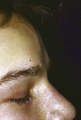
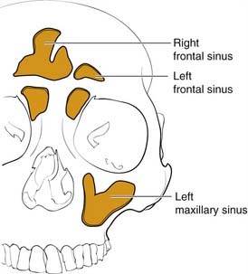
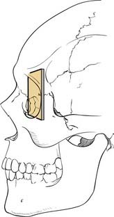
The frontal bone forms the contour of the forehead. Displaced fractures can create various deformities, the most common of which is a central forehead depression (Fig. 23-1). The frontal bone forms the junction between the cranium and the face, and it relates to several visceral structures, the most critical of which is the brain. The typically paired frontal sinuses, when present (approximately 85% of the time), are housed completely within the frontal bones (Fig. 23-2). Frontal bone fractures may involve only the anterior sinus walls, in which case the fractures are significant only for sinus function and cosmesis; or they may involve the posterior wall of the sinus or extend beyond the sinus, in which case they are true skull fractures and become neurosurgical concerns as well. The supraorbital rims and roofs are also part of the frontal bones, which are therefore also related to the orbits, and fractures can thus affect orbital and ocular functions. Inferiorly in the midline, the glabella portion of the frontal bone relates to the superior extent of the nasal bones. This thick glabellar bone protects the underlying frontal outflow tracts and the cribriform plates, which house the branches of the olfactory nerves. The supraorbital and supratrochlear nerves pass through notches or foramina in the supraorbital rims and can be injured from trauma or, more commonly, from surgical manipulation.
Middle Third
The middle third includes the zygomas, orbits, and maxillae, as well as the nose, which together with the anterior medial orbits form the central face. The anterior projection of the zygomas, the malar eminence, or “cheekbone prominences,” are important determinants of facial projection and contour. The posterolateral projections, the zygomatic arches, abut the temporal bones posteriorly and provide the attachments for the masseter muscles superiorly. The superior and medial projections of the zygoma contribute to the lateral and inferior orbital rims and the inferolateral orbital walls. Displacement of this portion of the zygoma can significantly alter the position of the globe in the orbit. The inferomedial extension of the zygoma extends from the inferior orbital rim and broadly contacts the maxilla, forming the important lateral buttress of the midface (Fig. 23-3). While the superior, medial, and inferior orbital rims extend anterior to the globe, the lateral rim, which is comprised primarily of the zygoma, is situated near the equator of the globe (Fig. 23-4).24 Therefore minor changes in the position of the zygoma can have a significant impact on the anteroposterior position of the globe. Enophthalmos is a common complication of inadequately repaired or unrepaired zygomatic fractures.
The maxilla also contains the infraorbital nerve, the terminal branch of V2, which provides sensation to the medial cheek, lateral nose, upper lip, and upper gingiva and teeth (Fig. 23-5). Fractures can compromise this nerve, and care must be taken to both preserve it and, if necessary, decompress it when repairing these fractures. The maxillae also house the maxillary sinuses, which drain into the middle meatus of the nose, lateral to the middle turbinates. Injury to the outflow tracts is uncommon, but preexisting obstruction may contribute to infection.
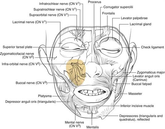
Figure 23-5. Front view of the partially dissected face. The infraorbital nerve is seen exiting the infraorbital foramen.
(Redrawn from Grant JCP. Grant’s Atlas of Anatomy. Baltimore: Williams & Wilkins; 1972, with permission.)
The orbits are complex bony structures with structural contributions from multiple facial and skull bones. In addition to the frontal, zygomatic and maxillary contributions discussed earlier, the lacrimal bone sits behind the maxillary bone medially (Fig. 23-6). The maxillary bone and the lacrimal bone together form the lacrimal fossa, which houses the lacrimal sac. The strong anterior (maxillary bone) and posterior (lacrimal bone) lacrimal crests provide the sites of attachment of the components of the medial canthal ligaments. Note that the medial canthal ligaments have three components, an anterior, a posterior, and a superior attachment (Fig. 23-7). The thin lamina papyracea of the ethmoid bone completes the medial orbital wall. The palatine bone makes a small contribution posteroinferiorly. The posterior lateral orbit is provided by the greater wing of the sphenoid and the solid optic canal bone is contributed by the lesser wing of the sphenoid. The optic canal sits posteromedially behind the medial wall where it is generally protected from all but the severest injury. The optic foramen is actually directed toward the lateral orbital rim rather than directly anteroposterior. The important “orbital apex” includes the area lateral to the optic canal through which cranial nerves III, IV, V, and VI pass to enter the orbit, which is considered part of the superior orbital fissure. When pressure from an injury (or tumor, abscess, hematoma) causes dysfunction in these nerves, it is called superior orbital fissure syndrome, which requires urgent surgical intervention.25,26
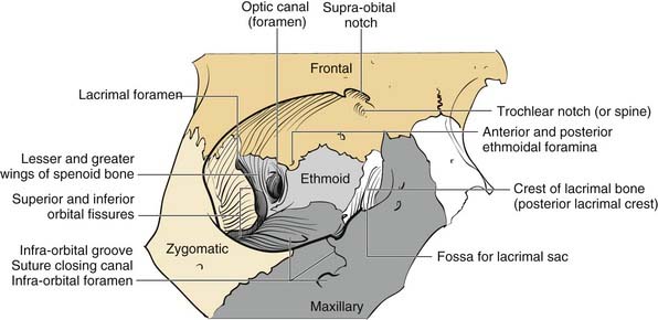
Figure 23-6. Bony orbital anatomy demonstrating the contributions of multiple bones.
(Redrawn with permission from Zide BM, Jelks GW. Surgical Anatomy of the Orbit. New York: Raven Press; 1985.)
Familiarity with the complex shape of the orbital walls is important for repair. The position of the globe is determined by the orbital shape and contents. The best way to prevent globe malpositions is to restore the natural shape of the orbit and ensure that orbital fat that has escaped through fractures is returned to the orbit. While the orbital floor is gently concave inferolaterally, it tends to be more convex medially and becomes significantly convex posteriorly behind the equator of the globe (see Fig. 23-6). Familiarity with this anatomy increases the likelihood of proper repair after injury.
The concept of the “central face” comes into play only in the presence of injury and refers to injury in which the trauma to the solid nasal root is transmitted posteriorly resulting in a telescoping injury. This has variously been called naso-orbital fractures, fracture of the ethmoids,27 nasoethmoid complex (NEC) fractures, and more recently naso-orbital-ethmoid (NOE) fractures. It is an important fracture clinically, but it takes on even greater significance when used as a paradigm for the understanding of how facial fractures occur and how the face is designed to provide maximum protection for structures important for the survival of the human organism.
This same concept can be applied to other aspects of facial skeletal anatomy. The globes tend to be protected in direct blunt trauma by the thin bones of both the orbital floors and medial walls. The globes are relatively round and suspended in fat so that most blunt traumas are transmitted to the thin orbital floors and medial walls, accounting for why “blowout fractures” are much more common than globe ruptures.27a Similarly, the face itself functions as a “shock absorber” for the cranial cavity, so that the frequency and severity of brain injury can be limited. Finally, this theory provides an explanation for the presence of the paranasal sinuses that offers a survival advantage: that is, the sinuses serve as a crumple zone for the face,27a allowing the energy to be dissipated before it reaches the eyes and brain. Thus the entire facial architecture has evolved by design to provide survival protection for critical organs (Table 23-1).
| Facial Crumple Zone | Area Protected |
|---|---|
| Medial orbital wall | Optic nerve, globe |
| Orbital floor | Globe |
| Maxillary sinus | Globe, middle cranial fossa |
| Ethmoid sinus | Globe, optic nerve, anterior cranial fossa, middle cranial fossa |
| Frontal sinus | Anterior cranial fossa |
| Sphenoid sinus | Carotid arteries, cavernous sinuses |
| Face as a whole | Cranial cavity |
| Condylar necks of mandible | Middle cranial fossae |
Lower Third
The mandible is generally considered the lower third of the facial structure. It contains the mandibular dentition, which interfaces with the maxillary dentition for mastication. Unlike the middle third, which is fixed to the skull, the mandible is mobile and swings, hinged to the skull base in two, bilaterally symmetric attachments. The hinges occur at the temporomandibular joints (TMJs), which are true arthrodial joints that both swing and slide. The conformation of the mandible, a somewhat horseshoe-shaped bone hinged in two places to the same solid entity, the skull, makes it well designed to absorb impact forces rather than transmit them to the solid middle fossa floor, and therefore multiple mandible fractures due to a single impact force are not uncommon. (Mandibular trauma causing injury to the skull base can occur, and the condylar head of the mandible has even rarely traversed the glenoid fossa, which houses the articular cartilage of the joint and entered the middle fossa, but such injuries remain rare.)28 The condylar head of the mandible is housed within the TMJ and is connected to the vertical ramus by the relatively thin and weak condylar neck. This weak area of the bone seems to give easily when a contralateral impact is applied, and fractures of this neck area are generally called subcondylar fractures, indicating that they occur below the TMJ. A central impact to the mentum does not uncommonly result in bilateral subcondylar fractures. The condylar neck extends inferiorly into the vertical ramus, which is also relatively thin compared to the tooth-bearing body and symphyseal regions of the bone. However, fractures of the vertical ramus (other than extensions of subcondylar fractures) are relatively uncommon, presumably due to the protective effects of the muscular sling provided by the muscles of mastication, all of which attach to aspects of the vertical rami. The powerful masseter muscle attaches broadly to the inferolateral surface of the ramus, whereas the pterygoids attach to the medial surface. The temporalis attaches to the coronoid process, a superior extension of the anterior ramus. The angle region of the mandible occurs at the posterior extent of the tooth-bearing region and is a common area for fracture. Fractures here extend from the thick, tooth-bearing area in the third molar region posteroinferiorly into the much thinner bone of the ramus. The presence of the third molar tends to thin the bone superiorly, and tension of the muscle sling may also splint the area, creating a natural break point. Fractures in this region are particularly difficult to stabilize, and repairs have traditionally resulted in the highest rates of complications (see later). As might be predicted, the mandible is thickest in the tooth-bearing areas. The anterior portion from canine to canine is referred to as the symphyseal region or symphysis (sometimes arbitrarily divided into symphysis in the midline and parasymphyseal regions on either side of the midline). From canine to the angle of the body of the mandible contains the two premolar (bicuspid) and three molar teeth. Another unique aspect of mandibular anatomy is the presence of the inferior alveolar nerve. A branch of the third division of the trigeminal nerve, the inferior alveolar nerve enters the mandible at the lingula and travels beneath the tooth roots that it supplies, exiting the mental foramen as the mental nerve, generally in the region of the first bicuspid tooth. It is important to keep in mind when repairing mandibular fractures that the mental foramen does not generally represent the most inferior position of the nerve, and this must be considered when placing hardware on the mandible in the body region behind the mental foramen.
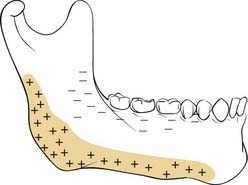
A common classification scheme for mandible fractures uses the terms favorable and unfavorable.29 However, this scheme has no impact on management and is not addressed here. It is also important to be familiar with the changes that take place in the mandible with age and tooth loss. When people lose teeth, the normal stresses on the bone are significantly altered, and bone remodeling tends to result in atrophy of the alveolar portion of the bone. The tooth-bearing portions of the mandible atrophy from the top down, bringing the inferior alveolar nerve closer and closer to the oral surface; in extreme cases, it can even rest on top of the bone. In addition, atherosclerosis of the inferior alveolar artery occurs, limiting the blood supply to the thin atrophic bone.30 This has significant implications for repair of these fractures.
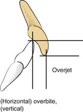
A knowledge of basic dental anatomy and familiarity with normal and common abnormal occlusal relationships is important for anyone treating fractures in the tooth-bearing facial bones. The normal adult complement of teeth is 32, with eight in each quadrant of the maxilla and mandible. Common numbering in adults in the United States is from 1 to 32, starting from the right maxillary third molar (number 1) counting toward the left with the left maxillary third molar being number 16, the left mandibular third molar being number 17, and ending with the right mandibular third molar being number 32. The dental surfaces contain cusps for chewing and grooves between these cusps, and in multicusp teeth these are identified by their positions as mesial (toward the incisors), distal (toward the posterior mandible or maxilla), buccal (toward the cheek), and lingual (toward the tongue). Occlusion is complex and has many aspects, but a normal molar relationship has been defined by Angle as the “mesiobuccal cusp of the maxillary first molar sitting within the mesiobuccal groove of the mandibular first molar.”31 This is Angle’s class I. When the maxillary molar is more anterior (chin generally relatively retruded), it is class II, and when the maxillary molar is more posterior (chin relatively prognathic), it is Angle’s class III. The maxillary arch should be wider than the mandibular, and when the maxillary buccal cusps fall lingual to the mandibular buccal cusps, there is a crossbite on that side. Similarly, anteriorly, the maxillary teeth should extend anterior to the mandibular teeth, which is defined as a normal overjet. The maxillary incisors should overlap the mandibular incisors vertically, which is defined as a normal overbite (Fig. 23-8).32
Evaluation and Diagnosis
Physical Examination
Upper Third
In the upper third of the face, the forehead is evaluated for sensation and motor function. In some cases, fractures may be visible as depressions (see Fig. 23-1) or palpable as step-offs, although typically these fractures are more readily seen on CT scans.
Middle Third
As noted earlier, the middle third of the face houses numerous structures. Of these structures, the eyes are the most important functionally. Vision should be assessed as soon as possible, because progressive visual loss demands emergency management. A light shined in the eye will evaluate pupillary response, even in the unresponsive patient. Failure of the pupil to respond can indicate injury to the afferent system (optic nerve) or efferent system (third cranial nerve and/or ciliary ganglion), or it could indicate a more serious intracranial condition. This must be immediately evaluated by both the neurosurgeon and the ophthalmologist. A CT scan is imperative to assess the nature and extent of injuries. Other significant but less serious dysfunctions include gaze limitation with or without diplopia. Forced duction testing is performed by anesthetizing the conjunctiva and then manually manipulating the globe in all directions with forceps. An applantation tonometer can also be used to determine whether there is an increase in pressure when the patient looks in the direction of gaze limitation (an increase in pressure of 4 mm Hg or more is indicative of entrapment).33 The position of the globe should be assessed both in its anteroposterior position (enophthalmos vs. proptosis) and its vertical position. The Hertel exophthalmometer is a good tool for measuring globe position when the lateral orbital rims are not displaced. Otherwise, devices that measure relative to the external auditory canal should be used (e.g., Naugle device).34 Enophthalmos may also be identified clinically, either by recognizing the more posterior position of the globe or sometimes by the deepening of the upper lid crease and elongation of the upper lid. Schubert recommends measuring the anteroposterior distance from the globe to the upper brow with the patient in the supine position, because the distance increases in the presence of enophthalmos.35 Chemosis and subconjunctival hemorrhage as well as periorbital ecchymosis are telltale signs of orbital injury. Although not universally accepted, regardless of the findings, if a periorbital fracture is identified, I believe that ophthalmologic evaluation should be performed before repair, because subtle injuries such as retinal tears may be a contraindication for surgery.
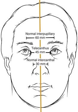
Telescoping fractures of the nasal, lacrimal, and ethmoid bones (so-called NEC or NOE fractures) require careful evaluation of the medial canthal relationships, and even with close study, they can still be missed. When the canthal ligament is fully avulsed (which is uncommon) or when the bone to which it attaches is completely detached (more common), the medial canthal ligament gets slowly pulled away from its natural position. It tends to displace laterally, anteriorly, and inferiorly, although the displacement may take place gradually and be missed during the acute phase. Careful assessment includes measurement of the horizontal palpebral widths and the intercanthal distance, as well as the distance between the nasal dorsal midline and each medial canthus. The two sides should be equal, and the intercanthal distance should be approximately equal to each horizontal palpebral width, both of which should be equal. It has also been described as one-half the interpupillary distance (Fig. 23-9).36 A loss of nasal dorsal height and development of epicanthal folds are other telltale signs. Finally, direct traction on the medial canthi should be performed to test the firmness of the attachment. A bimanual examination performed with an instrument in the nose and a finger over the medial canthal area as advocated by Paskert and Manson37 may also be attempted. Evaluation of the lacrimal collecting system is generally reserved for surgery.
Radiographic Evaluation
In general, the plane of the CT (axial vs. coronal) does make a difference in how effectively selected fractures are visualized.38,39 In a series of studies, fractures were created in fresh cadaveric heads, and these were scanned using various protocols. Dissections were then carried out to correlate the CT findings and to determine which planes of orientation yielded not only the best primary CT data but also the best three-dimensional reconstructions. It was found that axial orientation was best for visualizing most frontal fractures as well as NOE fractures and the zygomatic arches and vertical orbital walls. Coronal orientation was better for the orbital roofs and floors and the pterygoid plates. In general, as would be predicted, vertical structures were better seen on axial scans and horizontal structures were better seen on coronal scans. It was also found that scans performed at a resolution of less than 1.5 mm should not be used to make three-dimensional reconstructions, because the “fill-in” algorithms used by the computer programs created too many misrepresentations. In general, three-dimensional reconstructions create an overview picture that may help the surgeon visualize the overall facial architecture; however, they contain potential inaccuracies that are not present in directly obtained scans.
Upper Third
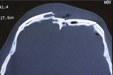
For frontal fractures, a high-resolution axial CT gives good information about the anterior and posterior walls (Fig. 23-10). However, in the presence of posterior wall fractures, it is impossible to determine the significance of soft tissue density inside the sinuses. When the posterior wall is displaced (regardless of the degree of displacement), and there is soft tissue density within the sinus, I recommend that the inside of the sinus be visualized (either directly or endoscopically). (We have had more than one experience in which placement of an endoscope in a sinus with minimal displacement of the posterior wall and no CSF leakage revealed brain tissue herniating into the sinus.) Displaced anterior wall fractures that require repair are commonly found on CT, even when there is no clinical evidence of cosmetic deformity. Fractures extending into the floor of the anterior fossa are best evaluated with a high-resolution CT scan.
Middle Third
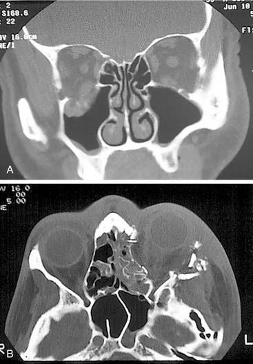
Simple orbital floor blowout fractures are best assessed via coronal CT scanning. However, if there is suggestion of extension into the medial wall, an axial scan (or a high-quality reconstruction from a 1.0 or 1.5 mm coronal) should be obtained as well (Fig. 23-11). In addition, for accurate orbital assessment, Schubert35 has recommended creating a parasagittal reconstruction in the plane of the optic nerve (which actually traverses the orbit from posteromedial to anterolateral, so it is not in a true sagittal plane).
Accurate assessment of orbital wall displacement allows the surgeon to anticipate the amount of enophthalmos that is likely to result if the fractures are not repaired.40–42 This not only helps determine the extent of orbital repair that will be necessary but also whether repair is required at all. CT evaluation of the optic canal and orbital apex take on critical significance in the presence of cranial neuropathies related to these areas. Visual loss due to trauma necessitates immediate analysis of orbital CT scans when possible, because a reversible injury causing constriction of the orbital apex may be identified.25,26
Displacement of maxillary fractures is typically well demonstrated on axial scans. These scans also show fractures through the pterygoid plates, which help define the presence of Le Fort type fractures. However, the horizontal components of these fractures are best displayed on coronal scans (and as might be expected on three-dimensional reconstructions from the coronal scans).43
Lower Third
For the mandible, unlike the middle and upper thirds of the face, most surgeons prefer plain radiographs, or more commonly panoramic tomography, and often both are the imaging techniques of choice. Several studies44,45 have found radiographic films to be better than CT scans, although 3-mm slice resolution was used in these studies. Wilson and colleagues,46 suggested that the addition of axial CT in 39 patients with mandible fractures revealed two parasymphyseal fractures and 15 cases of comminution or displacement that had been missed on panoramic tomography. However, the CT also missed posterior mandibular fractures, so that both were required to maximize information. However, 3- to 5-mm slice resolution was used, and this might account for the poor sensitivity of the CT scans in their series. In a subsequent study using high-resolution helical CT (1-mm slice resolution), the sensitivity for the CT scans was 100% while that for panoramic tomography was 86% (seven fractures missed in 6 of 12 patients).47 Considering the cost disparity between panoramic tomography and CT scanning, it is unclear whether the standard of care for mandibular evaluation will change. Lee has suggested that coronal CT scanning with three-dimensional reconstruction is the procedure of choice for assessing the position of the proximal fragment in subcondylar fractures of the mandible.6 Furthermore, he recommends a postoperative scan to assure that the reduction is accurate after endoscopic repair. This is certainly a more expensive approach than the Towne’s view radiographic study, which is typically used to view the position of the condylar fragment. Additional experience will ultimately determine the most appropriate studies.
Classification Schema
Upper Face
In the frontal area, classification schemes have focused on the involvement of the frontal sinuses, and these systems have been treatment oriented. The most useful classification, which predicts the likelihood of disruption of the frontal sinus drainage passages, was presented by Stanley and Becker.48 They separated frontal sinus fractures into linear horizontal and linear vertical and comminuted anterior and posterior walls, with and without NEC or supraorbital rim fractures. Of interest was the finding that whenever an NEC or a supraorbital rim fracture occurred in combination with comminuted fractures of either the anterior or posterior frontal sinus walls, a ductal injury was predicted. This scheme has been modified by Gonty and colleagues,49 but interestingly, in the commentary on this paper written by Stanley,50 he suggests that even his own classification system is not all that useful clinically. Numerous other classification systems have been suggested, but they offer little to the planning of the treatment approach.
There are also classification schema designed to predict the incidence of CSF rhinorrhea after anterior skull base trauma. The most useful of these, which is also somewhat intuitively predictable, was reported by Sakas and colleagues,51 who found that the more centrally located the fracture in the skull base and the more severe the fracture, the greater the likelihood of CSF leakage.
Middle Third
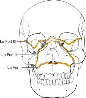
Numerous classification systems have been created for addressing the multiple fractures that occur in this area. Although not always applicable, the most important system is that developed more than 100 years ago by Rene Le Fort.52 It was developed artificially by analyzing the facial fracture patterns that were seen in cadavers that were traumatized by being dropped from a height. The Le Fort I fracture, or horizontal maxillary fracture, occurs above the level of the maxillary dentition, separating the alveoli and teeth from the remaining craniofacial skeleton. It crosses the nasal septum, and posteriorly it completes the fractures through the posterior maxillary walls and pterygoid plates. The Le Fort II fracture, or pyramidal fracture, starts on one side at the zygomaticomaxillary buttress, crosses the face in a superomedial direction, fracturing the inferior orbital rim and orbital floor, traverses the medial orbit, crosses the midline at the nasal root or through the nasal bones, and then travels inferolaterally across the contralateral side of the facial skeleton, creating a pyramidal shaped inferior facial segment that is separated from the remaining craniofacial skeleton. Like the Le Fort I, it fractures the nasal septum, the posterior maxillary walls, and the pterygoid plates. The Le Fort III fracture, or complete craniofacial separation, occurs at the level of the skull base, separating the zygomas from the temporal bones and frontal bones, crossing the lateral orbits and medial orbits, and reaching the midline at the nasofrontal junction, also violating the nasal septum and pterygoid plates (Fig. 23-12). Even though many fractures seen clinically do not fit precisely into this classification scheme, it has stood the test of time, and it does prove useful for communication and treatment planning. In order to use it for documentation purposes, it is helpful to more specifically describe the nature of the particular fractures in each case. For example, the pure Le Fort III fracture is probably a rare occurrence, yet many surgeons will describe an injury by the most severe level encountered and then describe the additional components.
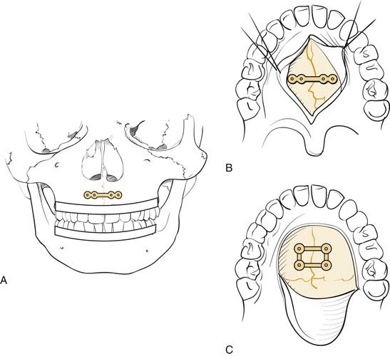
Numerous classification schemes have been used to describe NOE fractures. The system that is probably the most useful for treatment planning is that described by Markowitz and colleagues (Fig. 23-13).53 In this scheme, a type I fracture occurs when a large central fragment containing the medial canthal ligament is freed from the surrounding bone. It is repaired by rigidly fixing this central fragment in place. In a type II fracture, there is significant comminution, but the fragment containing the medial canthal ligament is still repairable. However, transnasal fixation of this fragment and/or the tendon is still necessary. In type III injuries, the tendon is either detached or attached to an unusable fragment. It must be freed and directly repaired with transnasal fixation. This description shows how a useful classification not only describes the injury but also helps in the planning of the repair.
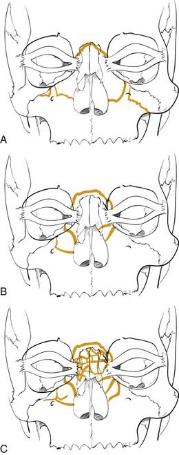
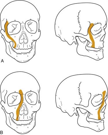
Figure 23-13. Naso-orbital ethmoid fractures have been classified as type I, type II, and type III by Markowitz and colleagues.53 The type I fractures (A) include a solid central segment to which the medial canthus is attached. Type II injuries (B) are more comminuted than type I but still leave a central segment to which the medial canthus is intact. In type III injuries (C), the bone is shattered and there is no solid bone to which the medial canthal tendon is attached.
(Redrawn from Markowitz BL, Manson PN, Sargent L, et al. Management of the medial canthal tendon in nasoethmoid orbital fractures: the importance of the central fragment in classification and treatment. Plast Reconstr Surg. 1991;87:843.)
Management
General
It is generally accepted that because most maxillofacial injuries are considered contaminated due to communication with the nose, sinuses, and/or oral cavity, antibiotic treatment should be initiated at the time the patient initially presents. A prospective study by Chole and Yee demonstrated some benefit of this approach.54 Typically, antibiotics that cover oral organisms such as penicillins, cephalosporins, or clindamycin are selected. It is unclear how long they should be continued, but they are generally administered until at least 24 hours after surgery, although they are sometimes given for longer periods.
An issue that has generated strong opinions is that of the timing of surgery. Early reviews of mandible fractures suggested that delay in treatment increased the likelihood of infection.55 However, since the advent of routine prophylactic antibiotic therapy, this does not seem to be true. Many surgeons have suggested that surgery should be delayed until swelling resolves so that facial asymmetries can be better assessed. However, because fractures are assessed using CT scans, this is probably not a relevant concern either, particularly because extensive soft tissue exposures recreate the soft tissue swelling anyway. More recent and cogent arguments have suggested that re-insulting the soft tissues after the acute inflammatory phase has resolved may result in a less pliable and resilient soft tissue envelope and less satisfactory healing and outcomes, although this remains more theoretical than proven. Certainly, logic seems to suggest that early intervention to restore the hard and soft tissues to their normal anatomic positions would be beneficial. However, it is not uncommon for other considerations to intervene, particularly in severe trauma in which the stabilization of the patient with life-threatening injuries takes priority. Thus the level of urgency remains an individual decision.
Surgical Access
The frequent use of extended access approaches56,57 has led to a better understanding of fracture patterns and the complexities of reduction and fixation. Combined with the use of rigid fixation techniques and the liberal use of bone grafts,58 repair of the facial skeleton has become more dependable, and the need for postsurgical maxillomandibular fixation (MMF) and tracheotomy has been minimized.59 However, there are also disadvantages to these wide exposures, and facial asymmetries may be seen in the presence of excellent skeletal reduction. These have been attributed to problems with soft tissue healing and redraping, leading surgeons to look for more limited access approaches that will still allow for correct bony repositioning.60
Upper Third
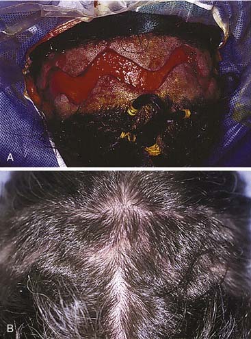
The workhorse of frontal and supraorbital rim exposure is the coronal incision. (Generally speaking, this incision is less obtrusive even in the bald or balding man than the bilateral brow, so-called butterfly or gull-wing incision. The exception might be a unilateral brow incision in the patient with bushy eyebrows, or in the presence of a significant laceration.) In the patient with hair, irregularizing the incision with a running W or a wavy line61 prevents the scar from parting the hair, making the scar virtually unnoticeable. However, a straight incision seems to be less visible on the bald scalp (Fig. 23-14).
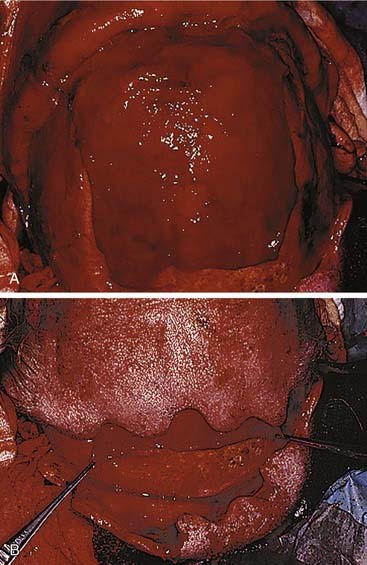
Shaving the hair is not required, although creating a hairless strip makes it easier to keep hair out of the wound during surgery and wound closure (Some neurosurgeons favor a complete shave when an intracranial injury is present.) When full exposure of the zygomas is required, the incision typically begins in the preauricular crease and extends superiorly above the auricle and over the top of the head to the contralateral auricle. The incision may curve anteriorly over the central scalp to shorten the skin flap, which allows the flap to flip more easily. When zygomatic exposure is not needed, the incision starts above the auricle. When a long pericranial flap is needed (for anterior fossa repair and/or frontal sinus obliteration), the incision should not violate the pericranium. The skin can then be elevated posteriorly over the pericranium, which is then incised more posteriorly and elevated with the anterior skin flap, thus creating a long, anteriorly based pericranial flap for later use (Fig. 23-15).
Middle Third
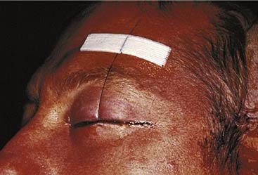
There are numerous options available to the surgeon for approaching the middle third of the facial skeleton, and the surgeon should select incisions based on the access needed to properly repair a particular injury, the ability to camouflage scars, and the surgeon’s experience. Zygomatic fractures are generally repaired at more than one site, often necessitating more than one surgical exposure. As noted earlier, the zygomatic arches are well exposed via the coronal incision. A simple arch fracture, however, may be accessed via a Gillies’ incision, which is made within the temporal hairline and elevated beneath the temporalis fascia (over the temporalis muscle, because the fascia inserts on the arch, while the muscle passes beneath the arch), allowing an instrument to be passed with assurance beneath the arch for elevation. Or it may be similarly approached using a transmucosal incision in the gingivobuccal sulcus intraorally. The frontozygomatic area (lateral orbital rim) may be accessed in several ways, and the facial plastic surgeon must select the most appropriate incision for the individual situation. The lateral upper lid incision (sometimes described as the “upper lid blepharoplasty incision”) is commonly used (Fig. 23-16), because it tends to hide well in the upper lid crease, and it is replacing the lateral brow incision, which, though still considered acceptable by many, not infrequently leaves a noticeable scar. The lateral rim can also be reached through a lower lid conjunctival incision, when the incision is extended laterally and a canthotomy is performed. However, an unacceptable amount of retraction may sometimes be required using this approach. The orbital floor, on the other hand, is well exposed via the transconjunctival incision through the lower lid. This can be performed using either a preseptal or a postseptal approach, and each has its advantages and disadvantages. Whichever approach is used, care must be taken to avoid injury to the orbital septum, because scarring in this layer tends to lead to postoperative lower lid malpositions. Extending these incisions to include a lateral canthotomy and skin incision allows wider exposure, particularly for placement of large grafts and for exposure of the medial and lateral orbits. The orbital floor can also be explored via transcutaneous incisions through the lower lid, including the subciliary and the lower lid crease incisions. The infraorbital incision has for the most part been abandoned due to limited access and excessive, prolonged lower lid swelling (except when there is already a significant laceration present). The medial orbit can be explored via a coronal incision, a transconjunctival incision (transcaruncular or retrocaruncular) or a cutaneous incision similar to an external ethmoidectomy approach. Note that whenever a lower lid incision is used, it is wise to place a Frost stitch at the end of the procedure and leave it in place for 24 to 48 hours. It is placed through the lower lid and taped to the forehead; it stretches the lower lid and may decrease the likelihood of lower lid malposition (Fig. 23-17).
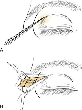
Figure 23-16. The upper lid blepharoplasty incision provides excellent access to the lateral orbital rim and lateral orbit.
(Redrawn from Bailey BJ, Calhoun KH. Atlas of Head & Neck Surgery—Otolaryngology, Philadelphia: Lippincott Williams & Wilkins; 2001.)
Lower Third (Mandible)
The mandible can be exposed either transmucosally or transcutaneously. Early concerns that intraoral exposures would lead to higher infection rates have not proved true in large experiences.62 Virtually all areas of the mandible can be reached via transoral incisions. The symphyseal region is easily exposed using an incision that is placed 5 to 10 mm below the gingival margin, thereby leaving enough free mucosa for easy wound closure. Body fractures can be similarly exposed. Care must be used to avoid injury to the mental nerve as it exits the mandible and enters the soft tissues to supply sensation to the overlying skin. The angle region is best exposed using an incision that begins at the inferior portion of the anterior ramus of the mandible. This is extended over the oblique line and carried below the gingival margin of the posterior molars. Finally, the vertical ramus and subcondylar regions are exposed using the vertical portion of this last incision and extending it superiorly. Exposure of the subcondylar region is enhanced with the aid of endoscopes.5–7
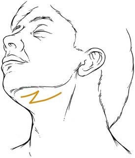
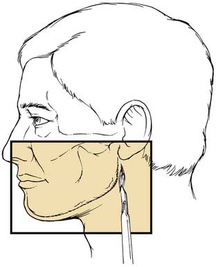
Extraoral incisions add the risk of a visible scar as well as the possibility of injury to the mandibular ramus of the facial nerve. On the other hand, for anterior body fractures, the risk of injury to the mental nerve may be decreased. The symphysis is best approached using a submental incision. The posterior body, angle, and even the subcondylar regions are best approached using a submandibular incision. To aid bone exposure and minimize retraction, the incision may be made one fingerbreadth or less below the mandible and elevated inferiorly superficial to the platysma. The platysma is incised two fingerbreadths below the mandible to minimize the risk to the facial nerve (Fig. 23-18). The anterior body is more difficult to reach transcutaneously, because the relaxed skin tension lines cross the mandible and risk injury to the facial nerve. This area is probably best approached by combining a submental incision with an anterior submandibular incision and connecting them via a Z to minimize the scar. The ramus and subcondylar regions can be approached via the submandibular incision and elevating between the masseter muscle and the bone. Alternatively, a retromandibular incision may be used as advocated by Ellis (Fig. 23-19).63 A preauricular incision may be used, but this may increase the risk of injuring the main trunk of the facial nerve, and if a preauricular approach is used, a facial nerve dissection should be considered for protection of the facial nerve.
Bone Healing
A cursory introduction to bone healing is included here from the standpoint of the interaction between repair techniques and the way that bone tends to heal. In general, like other injured tissue, bone tends to heal. The process begins almost immediately after injury with the development of a fracture hematoma. Subsequent ingrowth of vessels brings fibroblasts and other progenitor cells. There is a differentiation to chondroblasts, and these lay down fibrocartilage and chondroid matrix, which lead to early stabilization and provide the substrate for the development of osteoid. With differentiation into osteoblasts, osteoid is deposited, resulting in callus formation. It is helpful to think of callus as nature’s fixation device, in that callus is deposited until motion ceases at the site of the fracture. Once motion ceases, delicate osteons, each with their own delicate vessels, can grow across the fracture, resulting in the bridging of the fracture by new bone and thus full stabilization and healing.23,64 Once the fracture is bridged by bone, the bone form can then be remodeled to match its function according to Wolff’s law, which says that bone remodels according to the forces acting on it. This results in a re-creation of proper form to match function. This process tends to be very effective for long bone healing.
Bone healing via the differentiation cascade described earlier has been referred to as indirect or secondary bone healing to distinguish it from direct or primary bone healing, which only occurs when there is no motion across the fracture line.23 It appears that the bridging of a bony gap by bone can only occur in the absence of motion across that gap. The more motion that is present, the greater the amount of callus needed to stabilize the fragments so that healing by bone can eventually occur. Conversely, the more stable a repair and thus the less motion, the less callus that will form and the greater the likelihood that bone will directly bridge the fracture and heal the injury. It follows that when callus is unable to stabilize a fracture, bone will never form; the fracture remains bridged by fibrous tissue, thus forming a fibrous union, alternatively known as a nonunion, fibrous nonunion, or pseudoarthrosis (see Complications). To accomplish a stable repair, it is necessary to understand the biomechanics of the facial skeleton, and even more important, it is critical to use this understanding when applying fixation. Otherwise, motion tends to occur when the repair is loaded in function, and complications are then more likely to occur.
Biomechanics of the Facial Skeleton
The forces acting on the facial bones are complex and not yet fully elaborated.65 However, the current level of understanding provides enough information to guide rigid repair techniques that can result in a high success rate. On the other hand, disregarding these principles will likely result in higher than acceptable complication rates.
As discussed, the facial form is designed to support its function and to serve as a buffer to protect more critical organs from traumatic injury. Areas that support function must have strength along the paths of force. In the midface, these have been variously called pillars and buttresses, and these areas support the facial architecture during the powerful acts of biting and chewing.65–67 It is particularly important to reestablish these buttresses when they have been fractured. Furthermore, these buttresses are separated by areas of weakness, which seem to facilitate their acting as “crumple zones.” The mandible provides support to the dentition during biting and chewing. Because this bone swings from the cranium, forces generated when a bolus of food is compressed between the teeth result in a fulcrum effect that generates tension and compression zones in various areas (Fig. 23-20). These must be considered when repairing fractures, because the repairs must overcome both the forces exerted by muscular contraction and the forces created by particular functions such as chewing.
Middle Third
The middle third is more complex. The so-called pillars or buttresses accept the high forces of mastication without fracturing. These “vertical” buttresses have been described as lateral and medial on each side, as well as posterior (Fig. 23-21). The lateral buttress passes from the molar regions superiorly along the zygomaticomaxillary suture, through the solid malar eminence, then up along the lateral orbital rim and the frontozygomatic suture into the frontal bone. The medial buttress passes from the canine region superiorly along the solid bone that borders the piriform aperture, then superiorly along the solid frontal process of the maxilla into the frontal bone. As Rudderman and Mullen65 point out, the goal of repair is to reconstruct “load paths,” so that the bone can once again support the loads for which it was designed. In the middle third, this requires reestablishment of these four vertical buttresses, which support the impact forces of mastication. There is an additional posterior vertical buttress that transmits forces via the pterygoid plates to the skull base, but little attention is paid to this buttress because there is no access to repair it.
The zygoma forms an important attachment for the powerful masseter muscle. To support the function of this muscle, the bone needs to be solidly attached; yet in order to crumple, it also has to be able to give in response to a traumatic force. The multiple attachments of the so-called zygomatic “tripod” make this possible. Whether it is considered a tripod or quadrapod matters little; what is important is the nature of its attachments. The malar eminence is quite solid, but its attachments to the surrounding bone are less so. The zygomatic arch is quite thin, as is the inferior orbital rim. The lateral orbital rim is quite solid, and it is not uncommon for zygomatic fractures to be hinged from this attachment. The attachment to the remainder of the maxilla is broad (and continuous with the inferior orbital rim, thereby allowing the tripod nomenclature to make sense). Whereas the bone is relatively solid vertically to support the forces of mastication, it is actually thin bone that gives easily to a more horizontally or obliquely directed force. Repair requires stabilization of the zygoma in three dimensions. Traditional repairs focused on the most solid fixation point, and it was not uncommon for zygomatic fractures to be repaired with a single wire at the frontozygomatic fracture. The validity of this repair was called into question years ago,68 and more recent data have suggested that multiple fixation points are required to maintain the three-dimensional position of the zygoma against the strong masseteric pull.69 More recent repair techniques have focused on the zygomaticomaxillary buttress, because this is usually the mobile area, rather than on fixing the hinge point, which tends to be the frontozygomatic area.
Lower Third
Early explanations of mandibular biomechanics assumed a simple beam with forces along the top of the beam always creating tension zones superiorly (toward the alveolar surface) and compression zones inferiorly. This concept was introduced in Europe almost simultaneously by Spiessl14 in Switzerland and by Champy and colleagues17,19 in France. Interestingly, however, these two maxillofacial surgeons developed two entirely different repair techniques to overcome these forces, and two competing schools of thought developed as a result. Those who followed Spiessl and the Arbeitsgemeinschaft fur Osteosynthesefragen (AO) used compression plating techniques to repair most mandible fractures, and those who followed Champy used so-called miniplating techniques. Today, it has become apparent that there is room for both of these concepts, and it is more important to understand the biomechanics of fracture repair and to select a particular technique that has the highest likelihood of success in a given situation.
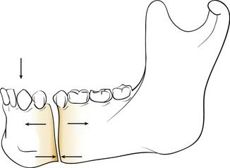
In the simple beam model, a fracture of the mandibular body is distracted superiorly (the tension zone) and compressed inferiorly (compression zone) when a force is applied to the dental surfaces anteriorly (e.g., chewing a bolus between the incisors) (Fig. 23-22). In this situation, controlling the tension zone results in a maintenance of reduction. Furthermore, when a force is applied by chewing anteriorly with the tension zone controlled, the compressive force in function is distributed across the length of the fracture. Once this is clearly understood, a variety of repair options become available to the head and neck surgeon. However, certain limitations created by the unique aspects of mandibular anatomy must first be overcome. These are the presence of tooth roots within the bone and the presence of the inferior alveolar nerve within the bone. Because it is important to preserve these structures uninjured, certain areas of the mandibular bone become unavailable for the placement of fixation appliances. Both Champy and Spiessl came to the same conclusions regarding the need to control the tension zones without injuring vital structures, but they solved the problem of avoiding the teeth and nerves in different ways. Champy chose to control the tension zone with small (“mini”) plates positioned carefully between the tooth roots and the inferior alveolar nerve using screws that pass through only one bony cortex, thereby minimizing the risk to the teeth and nerve in case the placement is imperfect. Spiessl shunned the use of these small plates with monocortical screws and instead used a well-placed arch bar across the dentition to control the tension zone and a larger compression plate using bicortical screws placed below the inferior alveolar nerve to maximize the amount of stabilization. The larger, compressive fixation was believed to be necessary in that it was being placed in a position that was actually biomechanically disadvantageous. However, using this approach, it is absolutely critical that the tension zone be controlled first; otherwise, the compression plate on the inferior mandible will distract the alveolar portion of the fracture. Ultimately, as it became clear that both of these techniques had high success rates, the battle between the schools of thought dissolved, and it is now clear that as long as biomechanical principles are properly followed, high success rates should be expected.70
Unfortunately, not all aspects of mandibular function follow this simple beam model. There are also irregularities of the mandibular bone that make some areas potentially more unstable than others. There appears to be greater potential for torque and rotational motion in the symphyseal region, so that when using miniplates, two are required to obtain a stable fixation in this area. A single miniplate appears to be adequate along the mandibular body, as long as the patient does not chew on the side of the fracture during the healing period. The angle region presents some particular problems, and it is the region in which the highest number of complications has always been noted.71,72 The angle region has thick bone superiorly and thin bone posteroinferiorly. There is often a tooth in the thick superior bone, and its presence may weaken the bone, but extracting this tooth (which may be unavoidable in some cases) tends to weaken the area even more. Furthermore, there is no dentition behind the fracture, so an arch bar lends no support to the repair. The complexity of forces acting on this area adds another challenge. It was first noted by Kroon and coworkers73 that depending upon where a bolus of food was placed along the mandibular dentition, the location of the compression zones and tension zones at the angle actually varied so much that the inferior area could change from compression to tension and vice versa. (Rudderman and Mullen65 confirmed this finding for other areas of the mandible as well.) The repair of the angle area remains controversial, but most authors agree that, although more difficult, time consuming, and demanding to apply, the larger, longer, mandibular reconstruction plates71,74 offer the most dependable repairs and the highest overall success rates. On the other hand, the desire to use easier and simpler techniques has resulted in a pushing of the envelope, and Potter and Ellis have recently advocated the use of a single 1.3-mm miniplate placed intraorally along the oblique line of the mandible as adequate fixation for mandibular angle fractures.75 A more recent report by Fox and Kellman76 suggests that when using miniplating techniques to repair mandibular angle fractures, two miniplates are best (and they should probably be 2 mm), as has been previously suggested by Levy and colleagues,72 as well as by Kroon and colleagues.73 In a recent prospective study, Siddiqui and associates found no significant difference in complications when using one or two miniplates to repair mandibular angle fractures.77
Fracture Repair
Occlusion
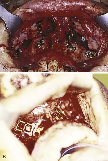
Occlusion is best reestablished using arch bars, which are pliable metal bands with hooks for wires or rubber bands that are wired directly to the teeth. The most common arch bar in the United States is the Errich arch bar. Other options include Ivy Loops, although these only stabilize a few teeth rather than the entire dental arch. They also do not provide tension banding across the mandibular dental arch. A variety of other options are available as well. A recent innovation has been the use of screws for MMF. Even though these can be placed quickly and easily, there are several disadvantages, the most common of which is the frequent penetration of tooth roots when placing them (Fig. 23-23).78 All arch bars tend to pull the dentition lingually, but the more inferior and buccal positioning of the screws when screw-MMF is used tends to increase this tendency.
Upper Third
Keep in mind the purposes of the bone being repaired. The anterior wall needs to be repaired for cosmetic reasons. The posterior wall needs to be managed to protect the anterior cranial fossa. The sinus outflow tracts must function to drain the sinuses, or the sinuses must be obliterated; otherwise chronic infection will result. Thus pure anterior wall fractures that do not extend into the nasofrontal ducts are repaired for cosmetic purposes only. These should be explored if they are significantly depressed, because even in the absence of acute deformity, they are likely to lead to deformities when the swelling resolves. The smallest plates available are generally used, and absorbable plates may work well in this area as well, because there are little or no force demands on the repair. Comminuted fragments may be pieced together and “lagged” with single screws to a plate that bridges the defect, or small fragments can be pieced together with small plates and/or wires. Use of the endoscope may allow repair of selected anterior wall fractures with minimal incisions. These techniques are currently in their infancy, and they are likely to become more prevalent as new instruments are developed to simplify the procedures. When the ducts are involved but the posterior wall is intact, judgment allows more than one option. Frontal sinus obliteration is always acceptable, but it is also reasonable to allow the sinus to function to see what happens. If the sinus becomes obstructed and acute or chronic sinusitis develops, the sinus can be opened endoscopically, or obliteration can be carried out at a later date.79 In the absence of posterior wall injury, nothing should be lost by this approach (as long as appropriate follow-up of the patient is assured).
The presence of posterior wall injury complicates the questions. A nondisplaced posterior wall fracture that does not demand exploration for ductal injury or for anterior wall displacement can be observed. However, if the posterior wall is displaced, it is difficult to determine the status of the dura and underlying brain. In the absence of apparent ductal injury, it is still wise to consider trephination and transcutaneous endoscopy, because unexpected herniation of brain into the sinus has been observed using this approach. (The dictum about a wall width of displacement has little meaning in this regard.) In the absence of posterior wall displacement and with no soft tissue abnormalities associated with such a nondisplaced fracture, it is unclear that obliteration is mandatory, even in the presence of ductal injuries. Careful follow-up including interval CT scans will demonstrate whether or not aeration of the sinus ensues. If chronic obstruction persists, then obliteration should be carried out. The choice of obliteration technique includes several options, and most seem to work. Fat has certainly withstood the test of time, as has bone and even leaving the sinus empty (after careful obstruction of the ducts with fascia) to allow for osteoneogenesis.80–84 Numerous complications have been encountered using hydroxyapatite cements,85,86 but in one series using it in combination with live pericranial flaps, no complications were seen.87 The cements do offer the unique advantage of contourability, so they can be used to repair the frontal contour in the presence of severe comminution and/or bone loss of the anterior wall (Fig. 23-24).
Finally, the option of obliteration via cranialization, that is, the complete removal of the posterior sinus walls, is reserved for cases in which the posterior walls are severely comminuted. Donald and Bernstein88,89 use this technique extensively whenever the posterior wall of the frontal sinus is involved in trauma. On the other hand, Schulz90 believes that obliteration of the frontal sinuses is never necessary. If the sinus is to be obliterated anyway, it seems logical that the additional layer of the posterior wall adds another barrier between the contaminated nasal cavity and the anterior fossa and should be reconstructed and preserved if possible.
CSF Rhinorrhea
In the presence of severe trauma with fractures of the anterior fossa, CSF rhinorrhea is not rare and may occur via the frontal sinuses, or through the cribriform plate, ethmoid sinuses, and/or sphenoid sinuses. Large defects should be repaired at the time of facial fracture repair. Small defects should be identified endoscopically and can usually be repaired using this approach. Careful examination of defects is important, because a transient leak may have stopped as a result of herniated brain, and late complications such as meningitis or death may occur if these are left untreated.91
Skull Base Disruption
In the presence of severe disruption of the anterior skull base, brain injury and CSF rhinorrhea are common. The best way to address these injuries is in collaboration with the neurosurgeons. The presence of brain injuries often lead to delays in management of the facial fractures and may actually increase the risk of meningitis. There is good evidence that the longer a CSF leak persists, the greater the risk of meningitis.51,92 Therefore, earlier intervention may decrease the risk of such complications. The use of the transglabellar subcranial approach may allow for earlier intervention, in that it allows more direct access to the anterior fossa floor without the need for significant retraction of the frontal lobes.93–96 It also allows direct visualization of the cribriform area without disarticulating it completely, so that many anterior fossa floor injuries may be repaired without completely sacrificing olfaction. The anterior fossa may be segregated from the nasal and sinus cavities, and the facial fractures may be repaired earlier, hopefully leading to better outcomes in these severely injured patients.93
Middle Third
Fractures that involve tooth-bearing segments are first stabilized at the level of the occlusion. Horizontal fractures above the occlusal level (Le Fort I) are repaired by reestablishing the four vertical buttresses, two medial and two lateral. Most surgeons repair these fractures using 1.5- to 2-mm L and J plates (Fig. 23-25), although other combinations and sizes may be used. It is important to ensure that two screws are placed on either side of each fracture plated, although more can be placed as long as tooth roots are not violated. The key is to fix these in the direction of the forces of mastication, so that chewing will not be likely to disrupt the repair.65
When the palate is fractured, it is important to ensure that the teeth have not rotated around the palatal fracture, which would result in lingual or buccal version of the teeth and a significant malposition of the bone fragments. In cases of severe disruption, particularly when alveolar segments are fractured and/or the mandible is similarly disrupted, a palatal splint may be needed to stabilize the dentition in the proper position. The palate may be repaired directly with a plate, or it may be stabilized along the premaxillary area if the occlusal stabilization is adequate to prevent rotation (Fig. 23-26).
Maxillary fractures at the Le Fort II level are similarly stabilized using 1.5- to 2-mm plates, again ensuring that at least two screws are placed on either side of each fracture plated (Fig. 23-27). A plate may be placed along the infraorbital rim to stabilize the upper portion of these fractures. Otherwise, when accessed, the nasal root should be rigidly fixated using very small plates (Fig. 23-28). It is critically important to be certain that the midface is not impacted and rotated superiorly before fixing the bones in place. Although MMF is applied first, it is actually possible to pull the patient into what appears to be good occlusion even though the midface is impacted; the mandibular teeth are pulled by the MMF toward the superiorly rotated maxilla, pulling the mandibular condyles out of the glenoid fossae. A patient may even remain in what appears to be good MMF for a full 6 weeks or longer, and when the MMF is released, the mandible returns to its neutral position revealing a significant anterior open bite. It is therefore important to recognize this at the time of surgery, so that the midface can be properly rotated downward into the correct position. If it is severely impacted, the Rowe midfacial disimpacters may be required to mobilize the midface and bring it down into its proper position. For many years, surgeons were more concerned about the possibility of facial elongation due to MMF pulling on unfixed maxillary fractures than they were about midfacial rotation and foreshortening. Therefore, the mainstay of treatment was Adams suspension wiring, in which the upper arch bar was wired to the zygomatic arches (or frontal bones when the zygomas were fractured) to prevent facial elongation; such treatment probably aggravated midfacial rotation and led to foreshortening and anterior open bite formation in many patients. With the advent of extended access approaches and routine exposure and fixation of midfacial fractures, this problem was recognized and is now carefully avoided. Similarly, with the availability of rigid fixation techniques, the use of halos for external fixation of midfacial fractures has become extremely uncommon. Nonetheless, familiarity with such techniques is of value in understanding the variety of surgical options.
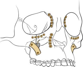
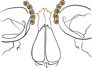
Figure 23-28. Diagrammatic representation of repair of the nasal frontal region with small plates and screws.
(Redrawn from Kellman RM, Marentette LJ. Atlas of Craniomaxillofacial Fixation. New York: Raven Press; 1995.)
Whereas the areas between the buttresses are not particularly important for structural support, the buttresses themselves are. Therefore, when bone is deficient along these buttresses, it should be replaced. A defect less than 5 mm in a single buttress can probably be safely bridged with a plate. Otherwise, defects should be bridged using bone grafts from another site. Split calvarium is a common source of bone graft material. It can be stabilized under a plate, or it may be used as a biologic plate and fixed to the bone at each end using lag screws (see Fig. 23-27).
The amount of stabilization (and therefore the amount of surgical exposure) required for fixation of zygomatic fractures may vary depending on the amount of instability and comminution of the fractures. Manson97 has suggested that the severity of the injury is determined by the amount of energy transmitted to the bone at the time of injury. This is implied by the injury, so it is the severity that is actually analyzed in planning the repair. However, for minimally displaced fractures, the zygoma tends to hinge at the frontozygomatic area and repair may require only percutaneous reduction, and it may pop into place and stay, or it may need only a sublabial exposure and fixation along the zygomaticomaxillary area. When greater force causes the injury, there tends to be comminution at the zygomaticomaxillary area, making this an inadequate point of reference for reduction. A lower lid exposure allows alignment of the infraorbital rim, as well as later exploration of the orbital floor if needed. Access to the lateral orbit is also particularly helpful, in that alignment of the zygoma with the greater wing of the sphenoid in the lateral orbit tends to be a dependable landmark for proper bony reduction. With more severe impacts, marked comminution may make it more difficult to be assured that the zygoma has been properly repositioned. A coronal incision allows full exposure of the entirety of the zygomatic arches. When the contralateral zygoma is intact, it serves as a good frame of reference. Otherwise, even wide exposure may not ensure accurate repositioning of the zygoma. Intraoperative radiography can be useful in this regard. The arch position can be checked using fluoroscopy.21 However, while not commonly available, intraoperative CT scanning certainly provides the most accurate assessment of bone position. Otherwise, a postoperative scan may indicate the need for revision surgery. Finally, it is important to keep in mind that although most orbital floor defects can be evaluated on preoperative CT scans, a potential orbital floor defect may not be visible. This occurs when the zygoma is severely impacted into the orbital space. After disimpaction of the zygoma, a previously absent orbital floor defect that requires repair may be present. Failure to look for this may result in unanticipated enophthalmos postoperatively. An endoscope placed into the maxillary sinus provides a minimally invasive way to assess the orbital floor in this situation. It is also important to repair the orbital rims before addressing the orbital walls, because the rim position will affect the globe position and the overall shape of the orbit.
The orbit itself needs to be restored as best as possible to its preinjury shape. This requires a familiarity with the normal orbital contours. A skull in the operating room may be helpful in this regard, and some surgeons even place a skull into a clear sterile bag and bend orbital wall implants on it. It is important to recognize the convexity on the orbital floor medially behind the equator of the globe. Failure to reconstitute this will create a tendency toward enophthalmos. It is also important to fill in significant defects in the medial wall for the same reason. Any trapped orbital tissues must be released into their normal positions in the orbit, and forced duction testing should be performed before and after all maneuvers in the orbit. The orbital wall contours can be reconstructed with autologous materials or with alloplastic materials, and each option has its particular advantages and disadvantages. Split calvarial bone is readily available, but it is very rigid and cannot be bent to shape.98 Molding requires cutting the bone and plating pieces together in different shapes. Split rib is more pliable and can be bent to shape, but it undergoes greater resorption. For small defects, nasal septal cartilage or bone and front face of maxillary bone have been used successfully. After release of the inferior rectus, a crack in the orbital floor can be covered with fascia or gelatin film. Titanium is easily moldable, but there is concern about the growth of fibrous tissue into holes in the material, although there are no actual reports of this being a problem. Porous polyethylene has become popular in the last few years for the repair of orbital floor defects, and it is replacing previously used materials that had variable extrusion rates. Most surgeons place orbital implants directly via transconjunctival and transcutaneous lid incisions, although recently the successful placement of these implants via the maxillary sinus using endoscopic assistance has been reported.4,99 Enophthalmos generally needs to be slightly overcorrected to compensate for the swelling that develops during the surgical procedure itself. Hypophthalmos (inferior eye position), on the other hand, should not be overcorrected, because overcorrection in this direction is more likely to persist.
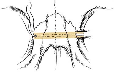
Naso-orbital ethmoid fractures (NOE, NEC) are among the most difficult to repair. Simple fractures in which the medial canthal ligaments remain attached to a significant, solid piece of central bone (type I) are repaired by stabilizing the solid piece of bone to the surrounding skeleton with plates. This must be properly positioned and fixed, or it will slowly lateralize, resulting in a significant deformity over time. Repair of the more severe type II and III injuries is a bit more controversial, and some argue for maintenance of any ligamentous attachments to bone, while others recommend focusing on the ligaments themselves.93–96 With the ligaments exposed (generally via a coronal incision), a permanent suture or wire is passed through the ligament and the suture is passed through the area of the posterior lacrimal crest (which may or may not be present), behind the nasal bones, through the nasal septum, out the same area on the contralateral side (using extreme caution to avoid injury to the contralateral globe), where it may be fixed either to the contralateral frontal bone (around a screw, through a plate hole, or through a hole in the supraorbital rim) or to the contralateral medial canthal ligament. A broad retractor (a sterilized teaspoon may be used) should cover and protect the contralateral globe during passing of wires or sutures from one side to the other. If this latter approach is done, tightening the wire fixes both medial canthal ligaments together. If the suture is fixed to the frontal bone, the same procedure must be repeated for the contralateral medial canthal ligament (assuming it is also damaged) (Fig. 23-29).
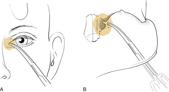
Great care must be used to ensure proper positioning and fixation of the canthal ligament. When identification of the medial canthal ligament is difficult, a hemostat may be placed in the caruncle and pushed medially. When examining the area from the deep surface, the ligament should be approximately in the area of the bulge created by the hemostat (Fig. 23-30). (Obviously, great care must be used to avoid corneal injury when using this technique). If the ligament is not fixed medially, it will slowly lateralize over time, resulting in unsightly telecanthus, malposition of the caruncle, horizontal shortening of the lids, and potential lacrimal dysfunction. It is also important to make certain that the full nasal dorsal height is reestablished, and bone grafts should be used if necessary. Failure to do so tends to exaggerate any appearance of telecanthus and increases the likelihood of developing epicanthal folds. Some surgeons advocate the placement of percutaneous supporting plates against the overlying nasal skin to recreate the natural concavity in this area. It is unclear whether these are necessary. Even though these are passed transnasally, these are not the same as the old percutaneous repairs of NOE fractures, which should not be used to repair these fractures, because they are, for the most part, ineffective.
Lower Third
There are a variety of treatment options for most fractures, and a familiarity with the basic principles of fracture repair allows the surgeon to select a preferred method for any given fracture. First, a familiarity with load-sharing and load-bearing repairs helps determine what options are available for the repair of a particular mandible fracture. A load-sharing repair depends on the integrity of the underlying bone, and the fixation appliance is positioned so as to ensure that the forces in function are borne by the bone itself. Thus, as discussed above, a small plate across the tension zone will ensure that the solid bone is pushed together in function so that it shares the load with the fixation appliance. Miniplate fixation, compression plate fixation, and lag screw fixation all represent load-sharing repairs and require adequate bone contact to succeed. On the other hand, when the bone is inadequate to share the load with the fixation appliance, as is seen when bone is too thin and atrophic, fractures are significantly comminuted, or there is bone loss, the repair has to bear the load across the repaired area, and thus a load-bearing repair is needed. This requires a repair that is strong enough to bear the load that is applied to the particular area in function, and thus a fairly long and strong plate is required. Until recently, 2.7-mm plates and screws were used for most load-bearing mandibular repairs; however, a strong 2.4-mm titanium mandibular reconstruction plate appears to be adequate in most instances. To successfully accomplish a load-bearing repair in the mandible, a minimum of three and preferably four solidly held bicortical screws should be placed in the bone on each side of the weak (defective) area.100 It should also be apparent, therefore, that a load-bearing type of reconstruction plate can be used as a fallback technique for any fracture, because, if it is strong enough to support a defect, it should be strong enough to repair any fracture. This is consistent with the finding noted above that a mandibular reconstruction plate (MRP) provides the most dependable repair of mandibular angle fractures.71,74
In the symphyseal region, when a load-sharing repair can be done, there are a number of options available to the maxillofacial surgeon. Because the bone is curved, there is a solid cortex on either side of the fracture that is accessible to screws. Therefore, lag screw fixation can be applied. When this is performed, it is recommended that two screws be used, and although it is not critical, it is probably better if the head of each screw comes in from the opposite side of the fracture (Fig. 23-31). It is also possible to use two miniplates, with a minimum of two screws on each side of the fracture through each miniplate. It is recommended that 2-mm screws be used. Once a good tension band arch bar (or miniplate) has been applied, a bicortical compression plate along the inferior border of the mandible is also an option.
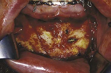
The angle region is more complex, and, as expected, the choice of repair technique is more controversial. The use of a tension band plate and a compression plate, while once advocated by proponents of AO technique,14,15 is no longer recommended.71 In fact, current AO philosophy recommends using either a miniplate technique or a reconstruction plate (load-bearing repair). However, the best miniplate approach remains controversial as well. Champy and associates18,19 recommend a single 2-mm miniplate placed along the oblique line of the angle region. The patient is then instructed not to chew on that side for 6 weeks. Kroon and coworkers73 on the other hand performed studies that demonstrated the changing location of the tension zone and therefore recommended using two miniplates at the angle. Levy and colleagues72 reviewed their experience using a single miniplate at the angle and compared the results with those in patients who had two miniplates placed at the angle. There was a significant difference in the outcomes, with the two miniplate group experiencing a 3.1% infection rate, compared with a 26.3% infection rate when a single miniplate was used. Fox and Kellman76 reported an infection rate of 2.9% in 72 patients using two four-hole 2-mm miniplates to repair angle fractures. Potter and Ellis, on the other hand, reported a low major complication rate using a single 1.3-mm miniplate along the oblique line.75 However, major complications were arbitrarily defined as requiring a return to the operating room, so that some complete failures did not count as major complications because they were managed in the office. As noted earlier, Siddiqui and colleagues saw no significant difference when one or two miniplates were used.97 However, the numbers were small. Thirty-six had one miniplate and 26 had two miniplates, and although there were many minor complications, there were no failures reported in either group, making it difficult to draw any definite conclusions. Finally, Niederdelmann and colleagues101 advocated a lag screw technique for mandibular angle fractures, but this is a difficult technique, and it should not be attempted unless the surgeon has extensive experience with these techniques.
The management of subcondylar fractures remains the most controversial, and many surgeons treat almost all of these with MMF, whereas some advocate routine open reduction for these fractures. It is interesting that the so-called closed reduction has been so well accepted for so many years, because it is really closed treatment and not reduction at all. MMF is used to train the mandible to return to its preinjury occlusion, and, combined with physiotherapy, a satisfactory outcome is typical. However, if radiographs are obtained at the completion of a period of closed reduction, the position of the condylar fragment is not likely to be altered. Even so, patients usually do reasonably well. If this approach is selected, it is recommended that the MMF be released after 10 to 14 days, so that physiotherapy can be initiated early. Some surgeons are recommending no MMF, treating the patient instead with immediate physiotherapy. If the patient develops a malocclusion, the surgeon has the option of replacing the MMF (usually using training elastics) or of reconsidering open reduction. On the other hand, it is not clear that patients do much better when a true open reduction is accomplished, and this fact, combined with the traditionally significant risk of facial nerve injury (which is indeed a major complication), has led to the acceptance of closed treatment. Most surgeons have accepted the classic indications for open reduction reported by Zide and Kent in 1983,102 including (1) condylar displacement into the middle fossa, (2) inability to obtain reduction, (3) lateral extracapsular displacement of the condyle, and (4) invasion by a foreign body. The relative indications they offered are more frequent, including (1) bilateral condylar fractures in an edentulous mandible when no splint is available, (2) condylar fractures when splinting is not recommended, (3) bilateral condylar fractures along with comminuted midface fractures, and (4) bilateral condylar fractures associated with gnathologic problems. In truth, recent prospective studies have suggested that patients actually do better after open reduction than closed treatment.103–106 The key issue is whether or not the unacceptable complication of facial nerve paralysis can be lowered to an acceptable level to justify routine open reduction of these fractures. In recent years, the introduction of endoscope-assisted transoral repair of these fractures seems to be changing the paradigm somewhat.5–9107 Unfortunately, while the overall success rate is high and the complication rate exceedingly low, the endoscopic repair of subcondylar fractures remains a challenging technique with a steep learning curve, and it requires specialized instrumentation to facilitate its performance.5 However, as greater experience is obtained, it is not unlikely that it will become a more commonplace technique, and more subcondylar fractures will likely be opened, reduced, and rigidly fixed.
The issue of teeth in the line of mandibular fractures has evolved significantly over the last several decades. Before the routine use of antibiotics, the presence of a tooth in the fracture line was associated with a high incidence of infection and even osteomyelitis.108 Dental extraction would minimize these complications, although they still were not rare. More recent reviews have still noted a higher incidence of infection when a fracture occurs through or around a tooth, but extraction no longer decreases the already lower infection rate. Thus there does not appear to be an indication to extract an otherwise healthy tooth, as long as it is not interfering with the reduction. On the other hand, an abscessed or infected tooth in the line of fracture should be extracted. Note that in the region of the angle, the third molar contributes significantly to the cross-sectional area of the bone, and extracting it tends to destabilize the fracture and its repair.71 Iizuka and Lindqvist71 found that a higher complication rate resulted when these teeth were extracted at the time of repair of angle fractures. They therefore recommend that the angle fracture be stabilized before the extraction using a load-bearing repair, following which the tooth may be extracted.
Edentulous Mandible
Mandibular atrophy is an even bigger problem, in that it has traditionally led to unacceptably high complication rates. A common misconception is that because the mandible is small, only a small plate is required to repair it. In fact, the forces on the mandible continue to be large and the small amount of bone available means that there is limited bone-to-bone contact for healing, and the thin bone does not provide enough support to adequately share the load with small fixation plates. Thus, the atrophic mandible is a contraindication to a load-sharing repair. To minimize the complication rate, a load-bearing repair must be used, and this requires long, strong plates with multiple fixation points using bicortical screws. Because this approach has been used, the success rate for bone healing in these difficult fractures has risen dramatically.109
Future Directions and New Horizons
It is impossible to predict exactly how the problems discussed herein will be managed in the future. However, some of the new technologies currently being used can provide some insight into the directions that developments are going. The recent introduction of endoscopes into facial trauma management has already altered the way some surgeons manage mandible and orbital fractures,4–899 and some are already adapting these techniques to more complex fractures, such as zygomatic fractures3 and frontal fractures, and even a variety of maxillofacial osteotomies.110 The development of better CT-based planning and navigational technology may well result in the more frequent use of percutaneous techniques for the repositioning of facial bones.
Chen CT, Chen YR, Tung TC, et al. Endoscopically assisted reconstruction of orbital medial wall fractures. Plastic and Reconstructive Surgery. 1999;103(2):714-720.
Ellis EIII. Treatment of mandibular angle fractures using the AO reconstruction plate. J Oral Maxillofac Surg. 1993;51:250-254.
Fox AJ, Kellman RM. Mandibular angle fractures: two-miniplate fixation and complications. Arch Facial Plast Surg. 2003;5:464-469.
Gonty AA, Marciani RD, Adornato DC. Management of frontal sinus fractures: a review of 33 cases. J Oral Maxillofac Surg. 1999;57:372-379.
Gruss JS, Mackinnon SE, Kassel EE, et al. The role of primary bone grafting in complex craniomaxillofacial trauma. Plastic and Reconstructive Surgery. 1985;75(1):17-24.
Iizuka T, Lindqvist C. Rigid internal fixation of fractures in the angular region of the mandible: an analysis of factors contributing to difference complications. Plast Reconstr Surg. 1993;91:265-271.
Iizuka T, Lindqvist C, Hallikainen D, et al. Infection after rigid fixation of mandibular fractures: a clinical and radiologic study. J Oral Maxillofac Surg. 1991;49:585-593.
Kellman RM. Endoscopically assisted repair of subcondylar fractures of the mandible: an evolving technique. Arch Facial Plast Surg. 2003;5:244-250.
Kellman RM. Use of the subcranial approach in maxillofacial trauma. Facial Plastic Surg Clinics of North America. 1998;6(4):501-510.
Kellman RM. Safe and dependable harvesting of large outer-table calvarial bone grafts. Arch Otolaryngol Head Neck Surg. 1994;120(8):856-860.
Lee C, Mankani MH, Kellman RM, et al. Minimally invasive approaches to mandibular fractures. Facial Plast Surg Clin North Am. 2001;9:475-487.
Lee C, Mueller RV, Lee K, et al. Endoscopic subcondylar fracture repair: functional aesthetic, and radiographic outcomes. Plast Reconstr Surg. 1998;102:1434-1443.
Le Fort R. Etude experimentale sur les fractures de la machoire superieure. Rev Chir Paris. 1901;23:208.
Lindqvist C, Kontio R, Pihakari A, et al. Rigid internal fixation of mandibular fractures—an analysis of 45 patients treated according to the ASIF method. Int J Oral Maxillofac Surg. 1986;15(6):657-664.
Manson PN, Grivas A, Rosenbaum A, et al. Studies on enophthalmos. II. The measurement of orbital injuries and their treatment by quantitative computed tomography. Plast Reconstr Surg. 1986;77:203.
Manson PN, Hoopes JE, Su CT. Structural pillars of the facial skeleton: an approach to the management of Le Fort fractures. Plastic and Reconstructive Surgery. 1980;66(1):54-61.
Markowitz BL, Manson PN, Sargent L, et al. Management of the medial canthal tendon in nasoethmoid orbital fractures: the importance of the central fragment in classification and treatment. Plast Reconstruct Surg. 1991;87(5):843-853.
Mincy JE. Posttraumatic cerebrospinal fluid fistula of the frontal fossa. J Trauma Injury Infect Crit Care. 1966;6(5):618-622.
Raveh J, Laedrach K, Vuillemin T, et al. Management of combined frontonaso-orbital/skull base fractures and telecanthus in 355 cases. Arch Otolaryngol Head Neck Surg. 1992;118:605-614.
Rudderman RH, Mullen RL. Biomechanics of the facial skeleton. Clin Plastic Surg. 1992;19(1):11-29.
Sakas DE, Beale DJ, Ameen AA, et al. Compound anterior cranial base fractures: classification using computed tomography scanning as a basis for selection of patients for dural repair. J Neurosurg. 1998;88:471-477.
Stanley RBJr. Reconstruction of midface vertical dimension following Le Fort fractures. Arch Otorhinolaryngol. 1984;110:571.
Wilson IF, Lokeh A, Benjamin CI, et al. Prospective comparison of panoramic tomography (zonography) and helical computed tomography in the diagnosis and operative management of mandibular fractures. Plast Reconstr Surg. 2001;107:1369-1375.
Wilson IF, Lokeh A, Benjamin CI, et al. Contribution of conventional axial computed tomography (nonhelical), in conjunction with panoramic tomography (zonography), in evaluating mandibular fractures. Ann Plast Surg. 2000;45:415-421.
Worsaae N, Thorn JJ. Surgical versus nonsurgical treatment of unilateral dislocated low subcondylar fractures: a clinical study of 52 cases. J Oral Maxillofac Surg. 1994;52:353-360.
1. Longaker MT, Kawamoto HK. Enophthalmos revisited. Clin Plast Surg. 1997;24(3):531-537.
2. Chen CT, Chen YR, Tung TC, et al. Endoscopically assisted reconstruction of orbital medial wall fractures. Plastic Reconstr Surg. 1999;103(2):714-720.
3. Chen CT, Lai JP, Chen R, et al. Application of endoscopies in zygomatic fracture repair. Br J Plast Surg. 2000;53:100-105.
4. Ikeda K, Suzuki H, Oshima T, et al. Endoscopic endonasal repair of orbital floor fracture. Arch Otolaryngol Head Neck Surg. 1999;125:59-63.
5. Kellman RM. Endoscopically assisted repair of subcondylar fractures of the mandible: an evolving technique. Arch Facial Plast Surg. 2003;5:244-250.
6. Lee C, Mankani MH, Kellman RM, et al. Minimally invasive approaches to mandibular fractures. Facial Plast Surg Clin North Am. 2001;9:475-487.
7. Lee C, Mueller RV, Lee K, et al. Endoscopic subcondylar fracture repair: functional aesthetic, and radiographic outcomes. Plast Reconstr Surg. 1998;102:1434-1443.
8. Rhee JS, Lynch J, Loehrl TA. Intranasal endoscopy-assisted repair of medial orbital wall fractures. Arch Facial Plast Surg. 2000;2:269-273.
9. Shumrick KA, Ryzenman JM. Endoscopic management of facial fractures. Facial Plast Surg Clin North Am. 2001;9(3):469-474.
10. Strong EB, Buchalter GM, Moulthrop THM. Endoscopic repair of isolated anterior table frontal sinus fractures. Arch Facial Plast Surg. 2003;5:514-521.
11. Adams WM. Internal wiring fixation of facial fractures. Surgery. 1942;12:523-540.
12. Kellman RM. Repair of mandibular fractures via compression plating and more traditional techniques: a comparison of results. Laryngoscope. 1984;94(12 Pt 1):1560-1567.
13. Lindqvist C, Kontio R, Pihakari A, et al. Rigid internal fixation of mandibular fractures—an analysis of 45 patients treated according to the ASIF method. Int J Oral Maxillofac Surg. 1986;15(6):657-664.
14. Spiessl B. New Concepts in Maxillofacial Bone Surgery. New York: Springer-Verlag; 1976.
15. Spiessl B. Stable internal fixation. In: Mathog RH, editor. Maxillofacial Trauma. Baltimore: Williams & Wilkins, 1984.
16. Michelet FX, Deymes J, Dessus B. Osteosynthesis with miniaturized screwed plates in maxillofacial surgery. J Maxillofac Surg. 1973;1:79.
17. Champy M, Lodde JP, Jaeger JM, et al. Osteosyntheses mandibulaires selon la technique de Mechelet. I. Bases biomecaniques. Rev Stomatol Chir Maxillofac. 1976;77:569.
18. Champy M, Lodde JP, Muster D, et al. Osteosynthesis using miniaturized screw-on plates in facial and cranial surgery. Ann Chir Plast Esthet. 1977;22:261.
19. Champy M, Pape HD, Gerlach KL, et al. The Strasbourg mini plate osteosynthesis. In: Kruger E, Schilli W, Worthington P, editors. Oral and Maxillofacial Traumatology, Vol 2. Chicago: Quintessence Publishing; 1986.
20. Ellis E3rd. Outcomes of patients with teeth in the line of mandibular angle fractures treated with stable internal fixation. J Oral Maxillofac Surg. 2002;60(8):863-866.
21. Kobienia BJ, Sultz JR, Migliori MR, et al. Portable fluoroscopy in the management of zygomatic arch fractures. Ann Plast Surg. 1998;40:260-264.
22. Stanley RBJr. Use of intraoperative computed tomography during repair of orbitozygomatic fractures. Arch Facial Plast Surg. 1999;1:19-24.
23. Rahn BA. Theoretical considerations in rigid fixation of facial bones. Clin Plast Surg. 1989;16(1):21-27.
24. Pearl RM. Treatment of enophthalmos. Clin Plast Surg. 1992;19(1):99-111.
25. Funk GF, Stanley RB, Becker TS. Reversible visual loss due to impacted lateral orbital wall fractures. Head Neck. 1989;11:295-300.
26. Stanley RBJr. The temporal approach to impacted lateral orbital wall fractures. Arch Otolaryngol Head Neck Surg. 1988;114:550-553.
27. Dawson RLG, Fordyce GL. Complex fractures of the middle third of the face and their early treatment. Br J Surg. 1953;41:254.
27a. Kellman RM, Schmidt C. The paranasal sinuses as a protective crumple zone for the orbit. Laryngoscope. 2009.
28. Kroetsch LJ, Brook AL, Kader A, et al. Traumatic dislocation of the mandibular condyle into the middle cranial fossa: report of a case, review of the literature, and a proposal management protocol. J Oral Maxillofac Surg. 2001;59:88-94.
29. Stanley RB. Pathogenesis and evaluation of mandibular fractures. In: Mathog RH, editor. Maxillofacial Trauma. Baltimore: Williams & Wilkins; 1984:136-147.
30. Bradley JA. Age changes in the vascular supply o the mandible. Br Dent J. 1972;132:142-144.
31. Wilson K, Hohmann A. Applied dental anatomy and occlusion. In: Mathog RH, editor. Maxillofacial Trauma. Baltimore: Williams & Wilkins; 1984:107-123.
32. Kellman RM, Tatum SA. Complex facial trauma with plating. In: Bailey BJ, editor. Head and Neck Surgery—Otolaryngology. Philadelphia: Lippincott-Raven; 2001:823-840.
33. Kellman RM, Bersani T. Delayed and secondary repair of posttraumatic enophthalmos and orbital deformities. Facial Plast Surg Clin N Am. 2002;10:311-323.
34. Schmitz JP, Parks W, Wilson IF, et al. The use of the Naugle orbitometer in maxillofacial trauma. J Craniomaxillofacial Trauma. 1999;5(1):13-18.
35. Schubert W. AO Advanced Course. Tucson, Arizona, February 2003.
36. Holt GR, Holt JE. Occipital and Orbital Trauma. AAO-HNSF Manual. Washington, DC. 1983.
37. Paskert JP, Manson PN. The bimanual examination of assessing instability in naso-orbitoethmoidal injuries. Plast Reconstr Surg. 1989;83(1):165-167.
38. Levy RA, Kellman RM, Rosenbaum AE. The effect of computed tomographic scan orientation on information loss in the three-dimensional reconstruction of tripod zygomatic fractures. Investig Radiol. 1991;26(5):427-431.
39. Levy RA, Rosenbaum AE, Kellman RM, et al. Assessing whether the plane of section on CT affects accuracy in demonstrating facial fractures in 3-D reconstruction when using a dried skull. Am J Neuroradiol. 1991;12(5):861-866.
40. Manson PN, Grivas A, Rosenbaum A, et al. Studies on enophthalmos. II. The measurement of orbital injuries and their treatment by quantitative computed tomography. Plast Reconstr Surg. 1986;77:203.
41. Parsons GS, Mathog RH. Orbital wall and volume relationships. Arch Otolaryngol Head Neck Surg. 1988;114:743-747.
42. Rubin PAD, Bilyk JR, Shore JW. Management of orbital trauma: fractures, hemorrhage, and traumatic optic neuropathy. Focal points. American Academy of Ophthalmology. 1994;12:1.
43. Levy RA, Edwards WT, Meyer JR, et al. Facial trauma and 3-D reconstructive imaging: insufficiencies and correctives. Am J Neuroradiol. 1992;13(3):885-892.
44. Creasman CN, Markowitz BL, Kawamoto HK, et al. Computed tomography versus standard radiography in the assessment of fractures of the mandible. Ann Plastic Surg. 1992;29(2):109-113.
45. Markowitz BL, Sinow JD, Kawamoto HK, et al. Prospective comparison of axial computed tomography and standard and panoramic radiographs in the diagnosis of mandibular fractures. Ann Plast Surg. 1999;42(2):163-169.
46. Wilson IF, Lokeh A, Benjamin CI, et al. Contribution of conventional axial computed tomography (nonhelical), in conjunction with panoramic tomography (zonography), in evaluating mandibular fractures. Ann Plast Surg. 2000;45:415-421.
47. Wilson IF, Lokeh A, Benjamin CI, et al. Prospective comparison of panoramic tomography (zonography) and helical computed tomography in the diagnosis and operative management of mandibular fractures. Plast Reconstr Surg. 2001;107:1369-1375.
48. Stanley RB, Becker TS. Injuries of the nasofrontal orifices in frontal sinus fractures. Laryngoscope. 1987;97:728-731.
49. Gonty AA, Marciani RD, Adornato DC. Management of frontal sinus fractures: a review of 33 cases. J Oral Maxillofac Surg. 1999;57:372-379.
50. Stanley RB. Management of frontal sinus fractures: a review of 33 cases. J Oral Maxillofac Surg. 1999;57:380-381.
51. Sakas DE, Beale DJ, Ameen AA, et al. Compound anterior cranial base fractures: classification using computed tomography scanning as a basis for selection of patients for dural repair. J Neurosurg. 1998;88:471-477.
52. Le Fort R. Etude experimentale sur les fractures de la machoire superieure. Rev Chir Paris. 1901;23:208.
53. Markowitz BL, Manson PN, Sargent L, et al. Management of the medial canthal tendon in nasoethmoid orbital fractures: the importance of the central fragment in classification and treatment. Plast Reconstr Surg. 1991;87(5):843-853.
54. Chole RA, Yee J. Antibiotic prophylaxis for facial fractures. A prospective, randomized clinical trial. Arch Otolaryngol Head Neck Surg. 1987;113:1055-1057.
55. Anderson T, Alpert B. Experience with rigid fixation of mandibular fractures and immediate function. J Oral Maxillofac Surg. 1992;50:555-560.
56. Gruss JS, Mackinnon SE, Kassel EE, et al. The role of primary bone grafting in complex craniomaxillofacial trauma. Plast Reconstr Surg. 1985;75(1):17-24.
57. Manson PN, Crawley WA, Yaremchuk MJ, et al. Midface fractures: advantages of immediate extended open reduction and bone grafting. Plast Reconstr Surg. 1985;76(1):1-12.
58. Gruss JS, Mackinnon SE. Complex maxillary fractures: role of buttress reconstruction and immediate bone grafts. Plast Reconstr Surg. 1986;78(1):9-22.
59. Kellman RM, Schilli W. Plate fixation of fractures of the mid and upper face. Otolaryngol Clin North Am. 1987;20:559-572.
60. Manson PN. Computed tomography use and repair of orbitozygomatic fractures. Arch Facial Plast Surg. 1999;1:25-26.
61. Fox AJ, Tatum SA. The coronal incision: sinusoidal, sawtooth, and postauricular techniques. Arch Facial Plast Surg. 2003;5(3):259-262.
62. Luhr HG, Drommer R, Holscher U, et al. Comparative studies between the extraoral and intraoral approach in compression-osteosynthesis of mandibular fractures. In: Hjorting-Hansen E, editor. Oral and Maxillofacial Surgery: Proceedings from the 8th International Conference on Oral and Maxillofacial Surgery. Chicago: Quintessence Publishing; 1985:133-137.
63. Ellis E, Zide MF. Surgical Approaches to the Facial Skeleton. Philadelphia: Williams & Wilkins; 1995.
64. Rahn BA. Direct and indirect bone healing after operative fracture treatment. Otolaryngol Clin North Am. 1987;20(3):425-440.
65. Rudderman RH, Mullen RL. Biomechanics of the facial skeleton. Clin Plast Surg. 1992;19(1):11-29.
66. Manson PN, Hoopes JE, Su CT. Structural pillars of the facial skeleton: an approach to the management of Le Fort fractures. Plast Reconstr Surg. 1980;66(1):54-61.
67. Stanley RBJr. Reconstruction of midface vertical dimension following Le Fort fractures. Arch Otorhinolaryngol. 1984;110:571.
68. Karlan MS, Cassisi NJ. Fractures of the zygoma. Arch Otolaryngol. 1979;105:32-327.
69. Davidson J, Nickerson D, Nickerson B. Zygomatic fractures: comparison of methods of internal fixation. Plastic Reconstr Surg. 1990;86(1):25-32.
70. Iizuka T, Lindqvist C, Hallikainen D, et al. Infection after rigid fixation of mandibular fractures: a clinical and radiologic study. J Oral Maxillofac Surg. 1991;49:585-593.
71. Iizuka T, Lindqvist C. Rigid internal fixation of fractures in the angular region of the mandible: an analysis of factors contributing to difference complications. Plast Reconstr Surg. 1993;91:265-271.
72. Levy FE, Smith RW, Odland RM, et al. Monocortical miniplate fixation of mandibular angle fractures. Arch Otolaryngol Head Neck Surg. 1991;117(2):149-154.
73. Kroon F, Mathisson M, Cordey J, et al. The use of miniplates in mandibular fractures. J Craniomaxillofac Surg. 1991;19:199-204.
74. Ellis EIII. Treatment of mandibular angle fractures using the AO reconstruction plate. J Oral Maxillofac Surg. 1993;51:250-254.
75. Potter J, Ellis EIII. Treatment of mandibular angle fractures with a malleable noncompression miniplate. J Oral Maxillofac Surg. 1999;57:288-292.
76. Fox AJ, Kellman RM. Mandibular angle fractures: two-miniplate fixation and complications. Arch Facial Plast Surg. 2003;5:464-469.
77. Siddiqui A, Markose G, Moos KF, et al. One miniplate versus two in the management of mandibular angle fractures: a prospective randomized study. Br J Oral Maxillofac Surg. 2007;45:223-225.
78. Alpert B. AO Advanced Course. Tucson, Arizona, February 2003.
79. Smith TL, Han JK, Loehrl TA, et al. Endoscopic management of the frontal recess in frontal sinus fractures: a shift in the paradigm? Laryngoscope. 2002;112:784-790.
80. Gerbino G, Roccia F, Benech A, et al. Analysis of 158 frontal sinus fractures: current surgical management. J Craniomaxillofac Surg. 2000;28:133-139.
81. Hardy JM, Montgomery WW. Osteoplastic frontal sinusotomy: an analysis of 250 operations. Ann Otol Rhinol Laryngol. 1976;85:523-532.
82. Rohrich RJ, Hollier LH. Management of frontal sinus fractures: changing concepts. Clin Plast Surg. 1992;19(1):219-232.
83. Sailer HF, Gratz KW, Kalavrezos ND. Frontal sinus fractures: principles of treatment and long term results after sinus obliteration with the use of lyophilized cartilage. J Craniomaxillofacial Surg. 1998;26:235-242.
84. Shumrick KA, Smith CP. The use of cancellous bone for frontal sinus obliteration and reconstruction of frontal bony defects. Arch Otolaryngol Head Neck Surg. 1994;120:1003-1009.
85. Friedman CD, Costantino PD, Jones K, et al. Hydroxyapatite cement. II: Obliteration and reconstruction of the cat frontal sinus. Arch Otolaryngol Head Neck Surg. 1991;117:385-389.
86. Mathur KK, Tatum SA, Kellman RM. Carbonated apatite and hydroxyapatite in craniofacial reconstruction. Arch Facial Plast Surg. 2003;5:379-383.
87. Petruzzelli GJ, Stankiewicz JA. Frontal sinus obliteration with hydroxyapatite cement. Laryngoscope. 2002;112:32-36.
88. Donald PJ, Bernstein L. Compound frontal sinus injuries with intracranial penetration. Laryngoscope. 1978;88:225-232.
89. Donald PJ. Frontal sinus ablation by cranialization: report of 21 cases. Arch Otol. 1982;108:142-146.
90. Schultz RC. Frontal sinus and supraorbital fractures from vehicle accidents. Clin Plast Surg. 1975;2(1):93-106.
91. Lewin W. Cerebral spinal fluid rhinorrhea in closed head injuries. Br J Surg. 1954;42:1-18.
92. Mincy JE. Posttraumatic cerebrospinal fluid fistula of the frontal fossa. J Trauma Injury Infect Crit Care. 1966;6(5):618-622.
93. Kellman RM. Use of the subcranial approach in maxillofacial trauma. Facial Plast Surg Clin North Am. 1998;6(4):501-510.
94. Raveh J, Laedrach K, Vuillemin T, et al. Management of combined frontonaso-orbital/skull base fractures and telecanthus in 355 cases. Arch Otolaryngol Head Neck Surg. 1992;118:605-614.
95. Raveh J, Redli M, Markwalder TM. Operative management of 194 cases of combined maxillofacial-frontobasal fractures: principles and surgical modifications. J Oral Maxillofac Surg. 1984;42:555-564.
96. Raveh J, Vuillemin T, Sutter F. Subcranial management of 395 combined frontobasal-midface fractures. Arch Otolaryngol Head Neck Surg. 1988;114:1114-1122.
97. Manson PN. Dimensional analysis of the facial skeleton: avoiding complications in the management of facial fractures by improved organization of treatment based on CT scans. Probl Plast Reconstr Surg. 1991;1(2):213-237.
98. Kellman RM. Safe and dependable harvesting of large outer-table calvarial bone grafts. Arch Otolaryngol-Head Neck Surg. 1994;120(8):856-860.
99. Chen CT, Lai JP, Tung TC, et al. Endoscopically assisted mandibular subcondylar fracture repair. Plast Reconstr Surg. 1999;103:60-65.
100. Haug RH. Effect of screw number on reconstruction plating. Oral Surg Oral Med Oral Pathol. 1993;75(6):664-668.
101. Niederdellmann H, Shetty V. Solitary lag screw osteosynthesis in the treatment of fractures of the angle of the mandible: a retrospective study. Plast Reconstr Surg. 1987;80:68-74.
102. Zide MF, Kent JN. Indications for open reduction of mandibular condyle fractures. J Oral Maxillofac Surg. 1983;41:89-98.
103. Ellis EIII, Simon P, Throckmorton GS. Occlusal results after open or closed treatment of fractures of the mandibular condylar process. J Oral Maxillofac Surg. 2000;58:260-268.
104. Ellis EIII, Throckmorton G. Facial symmetry after closed and open treatment of fractures of the mandibular condylar process. J Oral Maxillofac Surg. 2000;58:719-728.
105. Palmieri C, Ellis EIII, Throckmorton G. Mandibular motion after closed and open treatment of unilateral mandibular condylar process fractures. J Oral Maxillofac Surg. 1999;57(7):764-775.
106. Worsaae N, Thorn JJ. Surgical versus nonsurgical treatment of unilateral dislocated low subcondylar fractures: a clinical study of 52 cases. J Oral Maxillofac Surg. 1994;52:353-360.
107. Lauer G, Schmelzeisen R. Endoscope-assisted fixation of mandibular condylar process fractures. J Oral Maxillofac Surg. 1999;57:36-39.
108. Bradley RL. Treatment of the fractured mandible. Am Surg. 1965;31:289-290.
109. Luhr HG, Reidick T, Merten HA. Results of treatment of fractures of the atrophic edentulous mandible by compression plating: a retrospective evaluation of 84 consecutive cases. J Oral Maxillofac Surg. 1996;54(3):250-254.
110. Troulis MJ, Perrott DH, Kaban LB. Endoscopic mandibular osteotomy, and placement and activation of a semiburied distractor. J Oral Maxillofac Surg. 1999;57:1110-1113.
[/level-membership-for-otolaryngology-category][not-level-membership-for-otolaryngology-category]
CHAPTER 23 Maxillofacial Trauma
Borrowing from the revolutionary techniques of congenital craniofacial surgery pioneered by Paul Tessier, wider exposures have been possible, while visible scars have been minimized. Wider access has led to better understanding of common fracture patterns and their management, and, as might be expected, taking advantage of the experience gained from extended access approaches, surgeons are now trying to perform the same complex surgeries using less invasive techniques.1 Recently, these have been improved by taking advantage of the additional visualization made possibly by endoscopy.2–10
Bone repair techniques have evolved as well from the frequent use of interosseous wire repairs and Adams suspension wiring11 to the common use of rigid fixation with plates and screws. Many early mandibular fixations used large plates with large-diameter screws,12–15 and these repairs have progressed more recently to the frequent use of smaller (“miniplating”) techniques as advocated by Michelet and colleagues,16 Champy and associates,17–19 and more recently, Ellis.20 Microplates and even absorbable plates have been advocated for the repair of mid and upper facial as well as cranial fractures and osteotomies. Progress in understanding the biomechanical principles involved in facial fracture repair has resulted in more dependable repairs, both from the standpoint of the technology and in its application. Although not yet widely available, advanced intraoperative imaging techniques allow for more dependable and accurate restoration of the complex three-dimensional facial skeletal architecture.21,22
Advances in implant technology, particularly the wide use of titanium mesh, plates, and screws have led to better biocompatibility.23 Porous polyethylene implants so far seem to be well tolerated in the orbit, and such implants along with hydroxyapatite cements have provided a wider variety of options for craniofacial reconstruction. Finally, secondary (late) repair of unsatisfactory results has progressed as well, providing more options for the unfortunate patient with a poor outcome due to either an untreated injury or a suboptimal initial repair. This chapter focuses primarily on management, including evaluation and primary repair, with mention of complications and the treatment of unsatisfactory late outcomes.
Anatomy, Physiology, and Pathophysiology
Upper Third
The frontal bone forms the contour of the forehead. Displaced fractures can create various deformities, the most common of which is a central forehead depression (Fig. 23-1). The frontal bone forms the junction between the cranium and the face, and it relates to several visceral structures, the most critical of which is the brain. The typically paired frontal sinuses, when present (approximately 85% of the time), are housed completely within the frontal bones (Fig. 23-2). Frontal bone fractures may involve only the anterior sinus walls, in which case the fractures are significant only for sinus function and cosmesis; or they may involve the posterior wall of the sinus or extend beyond the sinus, in which case they are true skull fractures and become neurosurgical concerns as well. The supraorbital rims and roofs are also part of the frontal bones, which are therefore also related to the orbits, and fractures can thus affect orbital and ocular functions. Inferiorly in the midline, the glabella portion of the frontal bone relates to the superior extent of the nasal bones. This thick glabellar bone protects the underlying frontal outflow tracts and the cribriform plates, which house the branches of the olfactory nerves. The supraorbital and supratrochlear nerves pass through notches or foramina in the supraorbital rims and can be injured from trauma or, more commonly, from surgical manipulation.
Middle Third
The middle third includes the zygomas, orbits, and maxillae, as well as the nose, which together with the anterior medial orbits form the central face. The anterior projection of the zygomas, the malar eminence, or “cheekbone prominences,” are important determinants of facial projection and contour. The posterolateral projections, the zygomatic arches, abut the temporal bones posteriorly and provide the attachments for the masseter muscles superiorly. The superior and medial projections of the zygoma contribute to the lateral and inferior orbital rims and the inferolateral orbital walls. Displacement of this portion of the zygoma can significantly alter the position of the globe in the orbit. The inferomedial extension of the zygoma extends from the inferior orbital rim and broadly contacts the maxilla, forming the important lateral buttress of the midface (Fig. 23-3). While the superior, medial, and inferior orbital rims extend anterior to the globe, the lateral rim, which is comprised primarily of the zygoma, is situated near the equator of the globe (Fig. 23-4).24 Therefore minor changes in the position of the zygoma can have a significant impact on the anteroposterior position of the globe. Enophthalmos is a common complication of inadequately repaired or unrepaired zygomatic fractures.
The maxilla also contains the infraorbital nerve, the terminal branch of V2, which provides sensation to the medial cheek, lateral nose, upper lip, and upper gingiva and teeth (Fig. 23-5). Fractures can compromise this nerve, and care must be taken to both preserve it and, if necessary, decompress it when repairing these fractures. The maxillae also house the maxillary sinuses, which drain into the middle meatus of the nose, lateral to the middle turbinates. Injury to the outflow tracts is uncommon, but preexisting obstruction may contribute to infection.
Figure 23-5. Front view of the partially dissected face. The infraorbital nerve is seen exiting the infraorbital foramen.
(Redrawn from Grant JCP. Grant’s Atlas of Anatomy. Baltimore: Williams & Wilkins; 1972, with permission.)
The orbits are complex bony structures with structural contributions from multiple facial and skull bones. In addition to the frontal, zygomatic and maxillary contributions discussed earlier, the lacrimal bone sits behind the maxillary bone medially (Fig. 23-6). The maxillary bone and the lacrimal bone together form the lacrimal fossa, which houses the lacrimal sac. The strong anterior (maxillary bone) and posterior (lacrimal bone) lacrimal crests provide the sites of attachment of the components of the medial canthal ligaments. Note that the medial canthal ligaments have three components, an anterior, a posterior, and a superior attachment (Fig. 23-7). The thin lamina papyracea of the ethmoid bone completes the medial orbital wall. The palatine bone makes a small contribution posteroinferiorly. The posterior lateral orbit is provided by the greater wing of the sphenoid and the solid optic canal bone is contributed by the lesser wing of the sphenoid. The optic canal sits posteromedially behind the medial wall where it is generally protected from all but the severest injury. The optic foramen is actually directed toward the lateral orbital rim rather than directly anteroposterior. The important “orbital apex” includes the area lateral to the optic canal through which cranial nerves III, IV, V, and VI pass to enter the orbit, which is considered part of the superior orbital fissure. When pressure from an injury (or tumor, abscess, hematoma) causes dysfunction in these nerves, it is called superior orbital fissure syndrome, which requires urgent surgical intervention.25,26
Figure 23-6. Bony orbital anatomy demonstrating the contributions of multiple bones.
(Redrawn with permission from Zide BM, Jelks GW. Surgical Anatomy of the Orbit. New York: Raven Press; 1985.)
Familiarity with the complex shape of the orbital walls is important for repair. The position of the globe is determined by the orbital shape and contents. The best way to prevent globe malpositions is to restore the natural shape of the orbit and ensure that orbital fat that has escaped through fractures is returned to the orbit. While the orbital floor is gently concave inferolaterally, it tends to be more convex medially and becomes significantly convex posteriorly behind the equator of the globe (see Fig. 23-6). Familiarity with this anatomy increases the likelihood of proper repair after injury.
The concept of the “central face” comes into play only in the presence of injury and refers to injury in which the trauma to the solid nasal root is transmitted posteriorly resulting in a telescoping injury. This has variously been called naso-orbital fractures, fracture of the ethmoids,27 nasoethmoid complex (NEC) fractures, and more recently naso-orbital-ethmoid (NOE) fractures. It is an important fracture clinically, but it takes on even greater significance when used as a paradigm for the understanding of how facial fractures occur and how the face is designed to provide maximum protection for structures important for the survival of the human organism.
This same concept can be applied to other aspects of facial skeletal anatomy. The globes tend to be protected in direct blunt trauma by the thin bones of both the orbital floors and medial walls. The globes are relatively round and suspended in fat so that most blunt traumas are transmitted to the thin orbital floors and medial walls, accounting for why “blowout fractures” are much more common than globe ruptures.27a Similarly, the face itself functions as a “shock absorber” for the cranial cavity, so that the frequency and severity of brain injury can be limited. Finally, this theory provides an explanation for the presence of the paranasal sinuses that offers a survival advantage: that is, the sinuses serve as a crumple zone for the face,27a allowing the energy to be dissipated before it reaches the eyes and brain. Thus the entire facial architecture has evolved by design to provide survival protection for critical organs (Table 23-1).
| Facial Crumple Zone | Area Protected |
|---|---|
| Medial orbital wall | Optic nerve, globe |
| Orbital floor | Globe |
| Maxillary sinus | Globe, middle cranial fossa |
| Ethmoid sinus | Globe, optic nerve, anterior cranial fossa, middle cranial fossa |
| Frontal sinus | Anterior cranial fossa |
| Sphenoid sinus | Carotid arteries, cavernous sinuses |
| Face as a whole | Cranial cavity |
| Condylar necks of mandible | Middle cranial fossae |
Lower Third
The mandible is generally considered the lower third of the facial structure. It contains the mandibular dentition, which interfaces with the maxillary dentition for mastication. Unlike the middle third, which is fixed to the skull, the mandible is mobile and swings, hinged to the skull base in two, bilaterally symmetric attachments. The hinges occur at the temporomandibular joints (TMJs), which are true arthrodial joints that both swing and slide. The conformation of the mandible, a somewhat horseshoe-shaped bone hinged in two places to the same solid entity, the skull, makes it well designed to absorb impact forces rather than transmit them to the solid middle fossa floor, and therefore multiple mandible fractures due to a single impact force are not uncommon. (Mandibular trauma causing injury to the skull base can occur, and the condylar head of the mandible has even rarely traversed the glenoid fossa, which houses the articular cartilage of the joint and entered the middle fossa, but such injuries remain rare.)28 The condylar head of the mandible is housed within the TMJ and is connected to the vertical ramus by the relatively thin and weak condylar neck. This weak area of the bone seems to give easily when a contralateral impact is applied, and fractures of this neck area are generally called subcondylar fractures, indicating that they occur below the TMJ. A central impact to the mentum does not uncommonly result in bilateral subcondylar fractures. The condylar neck extends inferiorly into the vertical ramus, which is also relatively thin compared to the tooth-bearing body and symphyseal regions of the bone. However, fractures of the vertical ramus (other than extensions of subcondylar fractures) are relatively uncommon, presumably due to the protective effects of the muscular sling provided by the muscles of mastication, all of which attach to aspects of the vertical rami. The powerful masseter muscle attaches broadly to the inferolateral surface of the ramus, whereas the pterygoids attach to the medial surface. The temporalis attaches to the coronoid process, a superior extension of the anterior ramus. The angle region of the mandible occurs at the posterior extent of the tooth-bearing region and is a common area for fracture. Fractures here extend from the thick, tooth-bearing area in the third molar region posteroinferiorly into the much thinner bone of the ramus. The presence of the third molar tends to thin the bone superiorly, and tension of the muscle sling may also splint the area, creating a natural break point. Fractures in this region are particularly difficult to stabilize, and repairs have traditionally resulted in the highest rates of complications (see later). As might be predicted, the mandible is thickest in the tooth-bearing areas. The anterior portion from canine to canine is referred to as the symphyseal region or symphysis (sometimes arbitrarily divided into symphysis in the midline and parasymphyseal regions on either side of the midline). From canine to the angle of the body of the mandible contains the two premolar (bicuspid) and three molar teeth. Another unique aspect of mandibular anatomy is the presence of the inferior alveolar nerve. A branch of the third division of the trigeminal nerve, the inferior alveolar nerve enters the mandible at the lingula and travels beneath the tooth roots that it supplies, exiting the mental foramen as the mental nerve, generally in the region of the first bicuspid tooth. It is important to keep in mind when repairing mandibular fractures that the mental foramen does not generally represent the most inferior position of the nerve, and this must be considered when placing hardware on the mandible in the body region behind the mental foramen.
A common classification scheme for mandible fractures uses the terms favorable and unfavorable.29 However, this scheme has no impact on management and is not addressed here. It is also important to be familiar with the changes that take place in the mandible with age and tooth loss. When people lose teeth, the normal stresses on the bone are significantly altered, and bone remodeling tends to result in atrophy of the alveolar portion of the bone. The tooth-bearing portions of the mandible atrophy from the top down, bringing the inferior alveolar nerve closer and closer to the oral surface; in extreme cases, it can even rest on top of the bone. In addition, atherosclerosis of the inferior alveolar artery occurs, limiting the blood supply to the thin atrophic bone.30 This has significant implications for repair of these fractures.
A knowledge of basic dental anatomy and familiarity with normal and common abnormal occlusal relationships is important for anyone treating fractures in the tooth-bearing facial bones. The normal adult complement of teeth is 32, with eight in each quadrant of the maxilla and mandible. Common numbering in adults in the United States is from 1 to 32, starting from the right maxillary third molar (number 1) counting toward the left with the left maxillary third molar being number 16, the left mandibular third molar being number 17, and ending with the right mandibular third molar being number 32. The dental surfaces contain cusps for chewing and grooves between these cusps, and in multicusp teeth these are identified by their positions as mesial (toward the incisors), distal (toward the posterior mandible or maxilla), buccal (toward the cheek), and lingual (toward the tongue). Occlusion is complex and has many aspects, but a normal molar relationship has been defined by Angle as the “mesiobuccal cusp of the maxillary first molar sitting within the mesiobuccal groove of the mandibular first molar.”31 This is Angle’s class I. When the maxillary molar is more anterior (chin generally relatively retruded), it is class II, and when the maxillary molar is more posterior (chin relatively prognathic), it is Angle’s class III. The maxillary arch should be wider than the mandibular, and when the maxillary buccal cusps fall lingual to the mandibular buccal cusps, there is a crossbite on that side. Similarly, anteriorly, the maxillary teeth should extend anterior to the mandibular teeth, which is defined as a normal overjet. The maxillary incisors should overlap the mandibular incisors vertically, which is defined as a normal overbite (Fig. 23-8).32
Evaluation and Diagnosis
Physical Examination
Upper Third
In the upper third of the face, the forehead is evaluated for sensation and motor function. In some cases, fractures may be visible as depressions (see Fig. 23-1) or palpable as step-offs, although typically these fractures are more readily seen on CT scans.
Middle Third
As noted earlier, the middle third of the face houses numerous structures. Of these structures, the eyes are the most important functionally. Vision should be assessed as soon as possible, because progressive visual loss demands emergency management. A light shined in the eye will evaluate pupillary response, even in the unresponsive patient. Failure of the pupil to respond can indicate injury to the afferent system (optic nerve) or efferent system (third cranial nerve and/or ciliary ganglion), or it could indicate a more serious intracranial condition. This must be immediately evaluated by both the neurosurgeon and the ophthalmologist. A CT scan is imperative to assess the nature and extent of injuries. Other significant but less serious dysfunctions include gaze limitation with or without diplopia. Forced duction testing is performed by anesthetizing the conjunctiva and then manually manipulating the globe in all directions with forceps. An applantation tonometer can also be used to determine whether there is an increase in pressure when the patient looks in the direction of gaze limitation (an increase in pressure of 4 mm Hg or more is indicative of entrapment).33 The position of the globe should be assessed both in its anteroposterior position (enophthalmos vs. proptosis) and its vertical position. The Hertel exophthalmometer is a good tool for measuring globe position when the lateral orbital rims are not displaced. Otherwise, devices that measure relative to the external auditory canal should be used (e.g., Naugle device).34 Enophthalmos may also be identified clinically, either by recognizing the more posterior position of the globe or sometimes by the deepening of the upper lid crease and elongation of the upper lid. Schubert recommends measuring the anteroposterior distance from the globe to the upper brow with the patient in the supine position, because the distance increases in the presence of enophthalmos.35 Chemosis and subconjunctival hemorrhage as well as periorbital ecchymosis are telltale signs of orbital injury. Although not universally accepted, regardless of the findings, if a periorbital fracture is identified, I believe that ophthalmologic evaluation should be performed before repair, because subtle injuries such as retinal tears may be a contraindication for surgery.
Telescoping fractures of the nasal, lacrimal, and ethmoid bones (so-called NEC or NOE fractures) require careful evaluation of the medial canthal relationships, and even with close study, they can still be missed. When the canthal ligament is fully avulsed (which is uncommon) or when the bone to which it attaches is completely detached (more common), the medial canthal ligament gets slowly pulled away from its natural position. It tends to displace laterally, anteriorly, and inferiorly, although the displacement may take place gradually and be missed during the acute phase. Careful assessment includes measurement of the horizontal palpebral widths and the intercanthal distance, as well as the distance between the nasal dorsal midline and each medial canthus. The two sides should be equal, and the intercanthal distance should be approximately equal to each horizontal palpebral width, both of which should be equal. It has also been described as one-half the interpupillary distance (Fig. 23-9).36 A loss of nasal dorsal height and development of epicanthal folds are other telltale signs. Finally, direct traction on the medial canthi should be performed to test the firmness of the attachment. A bimanual examination performed with an instrument in the nose and a finger over the medial canthal area as advocated by Paskert and Manson37 may also be attempted. Evaluation of the lacrimal collecting system is generally reserved for surgery.
Radiographic Evaluation
In general, the plane of the CT (axial vs. coronal) does make a difference in how effectively selected fractures are visualized.38,39 In a series of studies, fractures were created in fresh cadaveric heads, and these were scanned using various protocols. Dissections were then carried out to correlate the CT findings and to determine which planes of orientation yielded not only the best primary CT data but also the best three-dimensional reconstructions. It was found that axial orientation was best for visualizing most frontal fractures as well as NOE fractures and the zygomatic arches and vertical orbital walls. Coronal orientation was better for the orbital roofs and floors and the pterygoid plates. In general, as would be predicted, vertical structures were better seen on axial scans and horizontal structures were better seen on coronal scans. It was also found that scans performed at a resolution of less than 1.5 mm should not be used to make three-dimensional reconstructions, because the “fill-in” algorithms used by the computer programs created too many misrepresentations. In general, three-dimensional reconstructions create an overview picture that may help the surgeon visualize the overall facial architecture; however, they contain potential inaccuracies that are not present in directly obtained scans.
Upper Third
For frontal fractures, a high-resolution axial CT gives good information about the anterior and posterior walls (Fig. 23-10). However, in the presence of posterior wall fractures, it is impossible to determine the significance of soft tissue density inside the sinuses. When the posterior wall is displaced (regardless of the degree of displacement), and there is soft tissue density within the sinus, I recommend that the inside of the sinus be visualized (either directly or endoscopically). (We have had more than one experience in which placement of an endoscope in a sinus with minimal displacement of the posterior wall and no CSF leakage revealed brain tissue herniating into the sinus.) Displaced anterior wall fractures that require repair are commonly found on CT, even when there is no clinical evidence of cosmetic deformity. Fractures extending into the floor of the anterior fossa are best evaluated with a high-resolution CT scan.
Middle Third
Simple orbital floor blowout fractures are best assessed via coronal CT scanning. However, if there is suggestion of extension into the medial wall, an axial scan (or a high-quality reconstruction from a 1.0 or 1.5 mm coronal) should be obtained as well (Fig. 23-11). In addition, for accurate orbital assessment, Schubert35 has recommended creating a parasagittal reconstruction in the plane of the optic nerve (which actually traverses the orbit from posteromedial to anterolateral, so it is not in a true sagittal plane).
Accurate assessment of orbital wall displacement allows the surgeon to anticipate the amount of enophthalmos that is likely to result if the fractures are not repaired.40–42 This not only helps determine the extent of orbital repair that will be necessary but also whether repair is required at all. CT evaluation of the optic canal and orbital apex take on critical significance in the presence of cranial neuropathies related to these areas. Visual loss due to trauma necessitates immediate analysis of orbital CT scans when possible, because a reversible injury causing constriction of the orbital apex may be identified.25,26
Displacement of maxillary fractures is typically well demonstrated on axial scans. These scans also show fractures through the pterygoid plates, which help define the presence of Le Fort type fractures. However, the horizontal components of these fractures are best displayed on coronal scans (and as might be expected on three-dimensional reconstructions from the coronal scans).43
Lower Third
For the mandible, unlike the middle and upper thirds of the face, most surgeons prefer plain radiographs, or more commonly panoramic tomography, and often both are the imaging techniques of choice. Several studies44,45 have found radiographic films to be better than CT scans, although 3-mm slice resolution was used in these studies. Wilson and colleagues,46 suggested that the addition of axial CT in 39 patients with mandible fractures revealed two parasymphyseal fractures and 15 cases of comminution or displacement that had been missed on panoramic tomography. However, the CT also missed posterior mandibular fractures, so that both were required to maximize information. However, 3- to 5-mm slice resolution was used, and this might account for the poor sensitivity of the CT scans in their series. In a subsequent study using high-resolution helical CT (1-mm slice resolution), the sensitivity for the CT scans was 100% while that for panoramic tomography was 86% (seven fractures missed in 6 of 12 patients).47 Considering the cost disparity between panoramic tomography and CT scanning, it is unclear whether the standard of care for mandibular evaluation will change. Lee has suggested that coronal CT scanning with three-dimensional reconstruction is the procedure of choice for assessing the position of the proximal fragment in subcondylar fractures of the mandible.6 Furthermore, he recommends a postoperative scan to assure that the reduction is accurate after endoscopic repair. This is certainly a more expensive approach than the Towne’s view radiographic study, which is typically used to view the position of the condylar fragment. Additional experience will ultimately determine the most appropriate studies.
Classification Schema
Upper Face
In the frontal area, classification schemes have focused on the involvement of the frontal sinuses, and these systems have been treatment oriented. The most useful classification, which predicts the likelihood of disruption of the frontal sinus drainage passages, was presented by Stanley and Becker.48 They separated frontal sinus fractures into linear horizontal and linear vertical and comminuted anterior and posterior walls, with and without NEC or supraorbital rim fractures. Of interest was the finding that whenever an NEC or a supraorbital rim fracture occurred in combination with comminuted fractures of either the anterior or posterior frontal sinus walls, a ductal injury was predicted. This scheme has been modified by Gonty and colleagues,49 but interestingly, in the commentary on this paper written by Stanley,50 he suggests that even his own classification system is not all that useful clinically. Numerous other classification systems have been suggested, but they offer little to the planning of the treatment approach.
There are also classification schema designed to predict the incidence of CSF rhinorrhea after anterior skull base trauma. The most useful of these, which is also somewhat intuitively predictable, was reported by Sakas and colleagues,51 who found that the more centrally located the fracture in the skull base and the more severe the fracture, the greater the likelihood of CSF leakage.
Middle Third
Numerous classification systems have been created for addressing the multiple fractures that occur in this area. Although not always applicable, the most important system is that developed more than 100 years ago by Rene Le Fort.52 It was developed artificially by analyzing the facial fracture patterns that were seen in cadavers that were traumatized by being dropped from a height. The Le Fort I fracture, or horizontal maxillary fracture, occurs above the level of the maxillary dentition, separating the alveoli and teeth from the remaining craniofacial skeleton. It crosses the nasal septum, and posteriorly it completes the fractures through the posterior maxillary walls and pterygoid plates. The Le Fort II fracture, or pyramidal fracture, starts on one side at the zygomaticomaxillary buttress, crosses the face in a superomedial direction, fracturing the inferior orbital rim and orbital floor, traverses the medial orbit, crosses the midline at the nasal root or through the nasal bones, and then travels inferolaterally across the contralateral side of the facial skeleton, creating a pyramidal shaped inferior facial segment that is separated from the remaining craniofacial skeleton. Like the Le Fort I, it fractures the nasal septum, the posterior maxillary walls, and the pterygoid plates. The Le Fort III fracture, or complete craniofacial separation, occurs at the level of the skull base, separating the zygomas from the temporal bones and frontal bones, crossing the lateral orbits and medial orbits, and reaching the midline at the nasofrontal junction, also violating the nasal septum and pterygoid plates (Fig. 23-12). Even though many fractures seen clinically do not fit precisely into this classification scheme, it has stood the test of time, and it does prove useful for communication and treatment planning. In order to use it for documentation purposes, it is helpful to more specifically describe the nature of the particular fractures in each case. For example, the pure Le Fort III fracture is probably a rare occurrence, yet many surgeons will describe an injury by the most severe level encountered and then describe the additional components.
Numerous classification schemes have been used to describe NOE fractures. The system that is probably the most useful for treatment planning is that described by Markowitz and colleagues (Fig. 23-13).53 In this scheme, a type I fracture occurs when a large central fragment containing the medial canthal ligament is freed from the surrounding bone. It is repaired by rigidly fixing this central fragment in place. In a type II fracture, there is significant comminution, but the fragment containing the medial canthal ligament is still repairable. However, transnasal fixation of this fragment and/or the tendon is still necessary. In type III injuries, the tendon is either detached or attached to an unusable fragment. It must be freed and directly repaired with transnasal fixation. This description shows how a useful classification not only describes the injury but also helps in the planning of the repair.
Figure 23-13. Naso-orbital ethmoid fractures have been classified as type I, type II, and type III by Markowitz and colleagues.53 The type I fractures (A) include a solid central segment to which the medial canthus is attached. Type II injuries (B) are more comminuted than type I but still leave a central segment to which the medial canthus is intact. In type III injuries (C), the bone is shattered and there is no solid bone to which the medial canthal tendon is attached.
(Redrawn from Markowitz BL, Manson PN, Sargent L, et al. Management of the medial canthal tendon in nasoethmoid orbital fractures: the importance of the central fragment in classification and treatment. Plast Reconstr Surg. 1991;87:843.)
