Chapter 15 Mammography
 A knowledge of the structure of the breast is essential to allow accurate positioning and interpretation of images during a mammography examination.

INTRODUCTION
ANATOMY OF THE BREAST
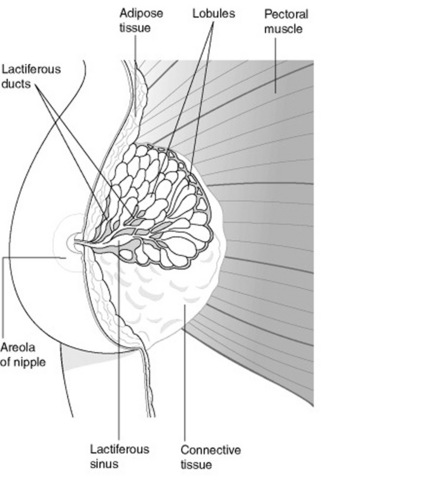
The adult breasts are two hemispherical organs situated on the anterior and lateral aspects of the chest wall, on the surface of the pectoralis major muscle (Fig. 15.1). The breast extends from the second rib superiorly (and clavicle) to the sixth rib inferiorly, and laterally from the mid-axillary line to the sternal edge medially. The glandular tissue in the upper outer quadrant of the breast, which extends into the axilla, is known as ‘axillary tail’. The nipple usually lies at the level of the fourth/fifth rib space; however, the breast is a mobile structure, which varies considerably in size and shape, so this should not be seen as a reliable surface marking.
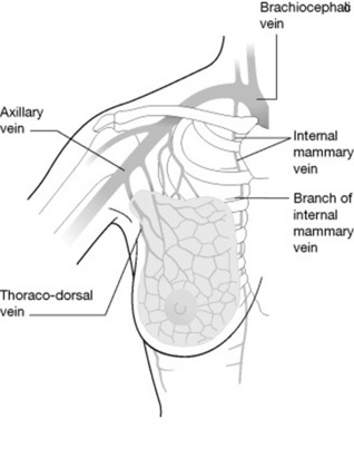
Figures 15.2 and 15.3 depict, respectively, the venous drainage and arterial supply of the breast.

LYMPHATIC DRAINAGE
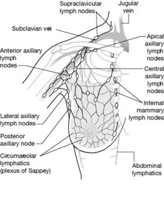
The lymph drains from the central portion of the breast, the circumareolar region and the skin surface, into a plexus of vessels on the surface of the pectoral muscle (Fig. 15.4). Approximately 75% of lymph drains into the axillary glands with only 25% passing from the medial half of the breast into the internal mammary nodes. There is also a limited amount of crossover between breasts and into the abdominal lymphatics. The relatively high occurrence of cancers in the upper outer quadrant and central areas of the breast and the fact that the majority of the lymphatic drainage passes into the axillary region have a direct importance in the selection of the mediolateral oblique as a screening position for breast cancer.1
HISTOLOGY OF THE BREAST AND RADIOGRAPHIC APPEARANCE
There are three main types of tissue within the breast:
MAMMOGRAPHY EQUIPMENT
Figure 15.5A shows a typical mammography unit and Figure 15.5B is of an X-ray unit showing the AEC position.
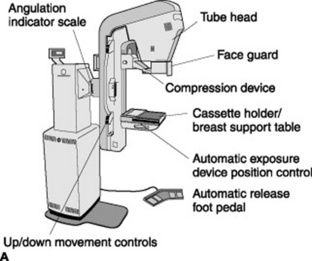
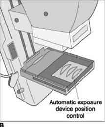
Figure 15.5 A A mammography unit. B A mammography X-ray unit showing position of automatic exposure control (AEC).
X-RAY TUBE AND HOUSING
A constant potential generator supplies the X-ray tube. The source–object distance (SID) is shorter than normal diagnostic X-ray examinations (45–60 cm) and the use of a fine focal spot of between 0.15 and 0.4 mm reduces geometric unsharpness. Image quality needs to be of an absolute high standard (i.e. micro calcifications, fine details).
With mammography equipment the tube housing is more compact than a standard X-ray tube (Fig. 15.6). The lower kVp employed is a favourable factor in permitting a smaller tube housing. Both high-tension cables enter the tube housing via the anode end to avoid patient contact. One particular type of unit has a system whereby the tube head moves out of the way during procedures such as biopsy or stereotactic localisation. As well as being able to move the X-ray tube head there is also a Perspex face guard to prevent the head from moving into the X-ray field. The tube is orientated with the anode further away from and the cathode closer to the patient, thus utilising the ‘anode heel effect’. The increased output at the cathode side of the X-ray tube is directed at the thicker chest wall edge of the breast whilst the ‘heel effect’ is over the thinner nipple edge.
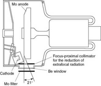
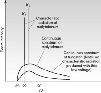
The main difference to a normal diagnostic tube is the use of molybdenum (Mb) as the target material. Traditionally, the only way to reduce the beam quality was to use a lower kVp; however, varying the target material and filtration can improve the penetrating power whilst reducing the glandular tissue dose in dense breasts. Tungsten (W) does not have any characteristic radiation at low voltages, unlike molybdenum (Fig. 15.7). Despite the lower intensity of brehmsstrahlung from molybdenum, this reduction in intensity is offset by the characteristic X-ray emission of molybdenum. Rhodium (Rh) is now also used as a target material and filter, its characteristic radiation is slightly higher than molybdenum,which makes it useful for patients with dense breast tissue or who have undergone radiation treatment or hormone therapy.
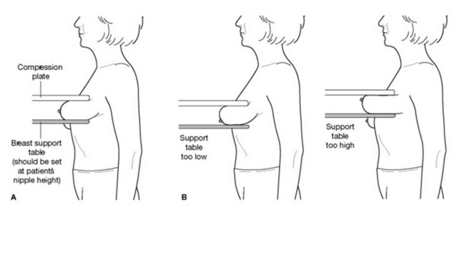
SUPPORT TABLE
The breast support plate must be height adjustable and rotate in different planes to accommodate the different needs of the patient. A digital display indicates the angulation of the breast support, which assists the radiographer in reproducibility of images. Within the support table there is the AEC, which corresponds to D-shaped areas on the Perspex compression plate so that its position relative to the underlying breast tissue can easily be seen. The AEC system has an array of eight solid-state measuring cells. The breast support table also houses the anti-scatter grid mechanism and the cassette tunnel (or the digital imaging system). There is an interlock to prevent double exposure of a cassette or the irradiation of a patient without a cassette in place.
COMPUTER AIDED DIAGNOSIS (CAD)
CAD is a sophisticated tool that identifies suspicious lesions and assists the radiologist/reader in the early detection of breast cancer. Triangular markers indicate possible microcalcification clusters and asterisk-shaped markers highlight regions suggesting masses or architectural distortion. The advantages of CAD may include the reduction in the number of individuals needed to interpret the images, together with an increase in sensitivity. However, research carried out has yet to show clear benefits from this technological advance.2,3
Technique
It may also be the policy to carry out a manual breast examination prior to mammography.
THE CRANIOCAUDAD PROJECTION
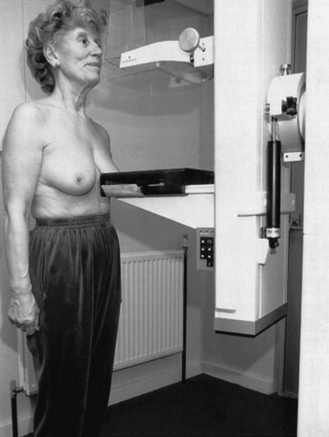
Stage 1: Woman stands in front of the X-ray equipment
Potential areas for errors in positioning at stage 1
Stage 2: Lifting the breast onto the support table
Potential areas for errors in positioning at stage 2
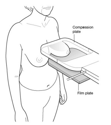
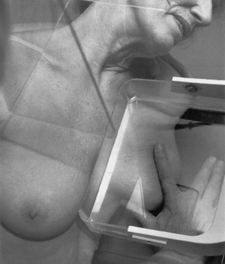
Stage 3: Compressing the breast onto the support table
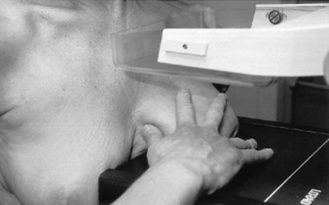
Potential areas for errors in positioning at stage 3
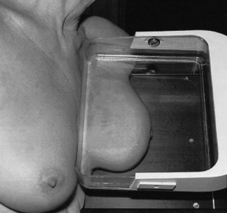
Stage 4: Compressed breast on the support table
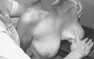
The breast should feel tense under the compression plate and there should be a slight blanching of the superior breast surface, accompanied by a slight reddening of the edge of the breast (Fig. 15.12).
Stage 5: Exposing and viewing the image
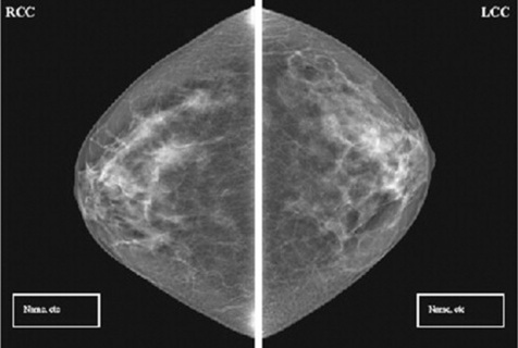
The craniocaudad projection/image is evaluated using the following criteria (Fig. 15.13):
PATIENT TYPES
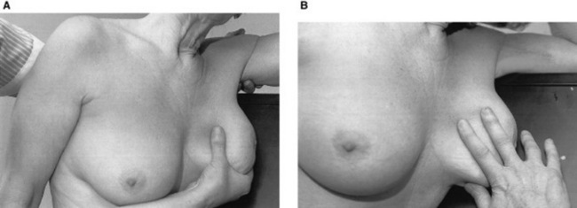
Hypersthenic individuals
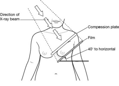
Short and stocky, with broad shoulders (Fig. 15.14), these patients benefit from an angle between the compression plate and horizontal of less than 45° and, potentially, 40°. The support table will then be at an angle, making it parallel to the middle axis of the breast tissue and thereby reducing the degree of foreshortening.
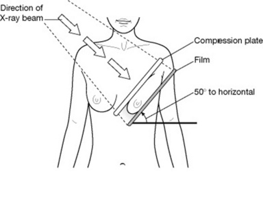
MEDIOLATERAL OBLIQUE TECHNIQUE
Stage 1: Woman stands in front of X-ray equipment

Potential areas for errors in positioning at stage 1
Stage 2: Lifting the breast onto the support table
Potential areas for errors in positioning at stage 2
Stage 3: Compressing the breast onto the support table
Potential areas for errors in positioning at stage 3
Stage 4: Compressed breast on the support table
The breast should feel tense under the compression plate, with a slight blanching of the medial breast surface accompanied by a slight reddening of the edge of the breast (Fig. 15.19).
Potential areas for errors in positioning at stage 4
Stage 5: Exposing and viewing image
The breast should be exposed and the compression released immediately post exposure, unless the woman is undergoing a localisation procedure (Fig. 15.20).
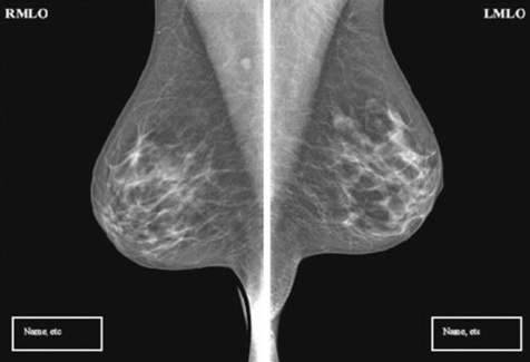
The mediolateral projection or image is evaluated using the following criteria:
PATHOLOGY
Breast cancer is the most common cancer detected in women in the UK. It currently accounts for 17% of annual female cancer deaths (13 000); however, this has been reduced from 15 000 per annum when the screening programme was first introduced in 1988. There is evidence from randomised-controlled trials of a significant reduction in mortality in the population with breast cancer.4
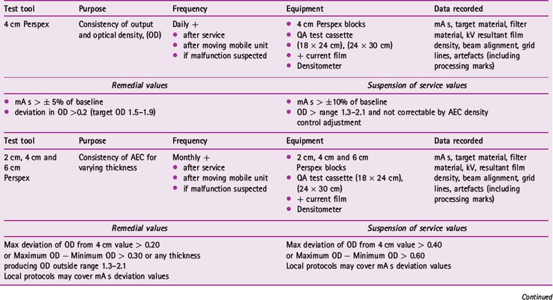
QUALITY ASSURANCE
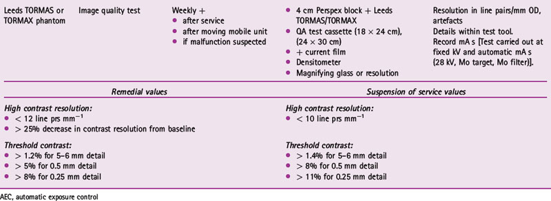
The quality assurance (QA) system in place for breast screening units covers not only the quality of the X-ray equipment and images. The daily, weekly and monthly QA processes that are carried out on the mammography equipment are seen in Table 15.1. Processing QA is carried out following the standard QA programme for all processors.
1 Lundgren B, Jakobsson S. Single view mammography. Cancer. 1976;38:1124-1129.
2 Gur D, Sumkin JH, Rockette HE, et al. Changes in breast cancer detection and mammography recall rates after the introduction of a computer-aided detection system. J Natl Cancer Inst. 2004;96:185-190.
3 Khoo L, Taylor P, Given-Wilson R. A prospective study of computer aided detection in one United Kingdom National Breast Screening Programme. Radiology. 2008. In press
4 Advisory Committee on Breast Cancer Screening. Screening for breast cancer in England: past and future. Sheffield: NHS Cancer Screening Programmes, 2006. NHSBSP Publication no 61
Lee L, Strickland V, Wilson AR, Roebuck E. Fundamentals of mammography. Oxford: Churchill Livingstone, 2003.
NHS Breast Screening Programme (NHSBSP). On-line. Available. 13 February 2008. www.cancerscreening.nhs.uk/breastscreen/index.html
Bushong SC. Radiological science for technologists: physics, biology and protection, 8th edn. St Louis: Mosby, 2004.
Carter P. Chesneys’ equipment for student radiographers, 4th edn. London: Blackwell Scientific, 1994.
Cox J. The impact of technology on working practice. Synergy. 2001;June:24-26.
Duthie S. Stereo core biopsy of the breast. Synergy. 2001;June:14-19.
MDA Evaluation Report (02103). Mammography X-ray unit, Instrumentarium Imaging Diamond. 2003.
Young KC, Oduko JM. Review of computerised radiography systems in the NHSBSP. NHS Cancer Screening Programmes. 2005. NHSBSP Equipment Report 0501


