Chapter 19 Magnetic resonance imaging
 MRI works because of the Larmor equation which states that

where ω is the precessional frequency of a proton, γ is the gyromagnetic ratio and B0 is the strength of the magnetic field.


INTRODUCTION
An MRI (magnetic resonance imaging) scanner is found in most hospitals today. It is an extremely valuable investigative tool and is an essentialpiece of equipment in a modern radiology department. The MRI scanner can produce high quality diagnostic images of almost any part of the human body.
TYPES OF MAGNET
There are many types of MRI magnet and a multitude of manufacturers who make them.
MRI SCANNING UNIT
TYPES OF SCANNER
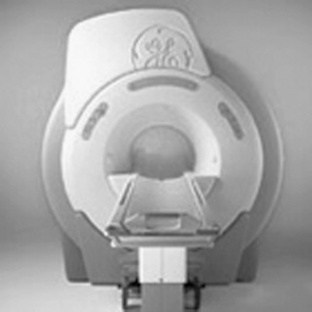
Scanners can be closed or open. Closed systems are the most commonly used (Fig. 19.1). These scanners are tube shaped and, although called a closed system, have an opening at each end. This tube is called the bore. On a modern 1.5 T system the bore is likely to have a diameter in the region of 50–60 cm.
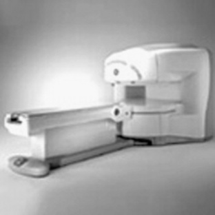
Open systems are not tube shaped and tend to be more open, as the name implies (Fig. 19.2). They use two doughnut shaped magnets that are placed above and below the patient.
THE PHYSICS BIT
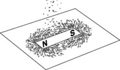
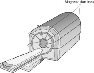
If a piece of card is placed over a bar magnet and then sprinkled with some iron filings, the filings line up with the magnetic field lines running from the north pole of the magnet to the south pole of the magnet (Fig. 19.3). The MRI scanner is just the same (however, the magnet is a lot stronger). The magnetic field lines run down the centre of the bore and extend around the sides of the scanner in the same pattern as the iron filings described above (Fig. 19.4).
A radiofrequency or an additional magnetic field/gradient is applied to flip these protons from the longitudinal plane to the transverse plane. Then the protons are allowed to relax backto the longitudinal plane. When they relax back they emit a small radio signal. This signal is picked up in an antenna or coil. Different tissues emit different intensities of signal and, with some clever computational analysis, we can differentiate these different intensities and their position and therefore produce a picture. This follows the Larmor equation.


THE COILS
MRI PULSE SEQUENCES
In MRI scanning there are different types of pulse sequence. The two main types are:
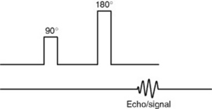
SPIN ECHO (SE) SEQUENCE
A 180 ° pulse follows a 90 ° pulse and then the signal is generated (Fig. 19.5).
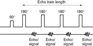
FAST SPIN ECHO (FSE/TSE) SEQUENCE
A 90 ° pulse is followed by a series of pulses (normally a 180 ° pulse), with a signal being generated after each 180 ° pulse (Fig. 19.6). The number of 180 ° pulses is called the ‘echo train length’ (ETL).
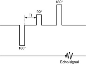
FLUID ATTENUATED INVERSION RECOVERY (FLAIR) AND SHORT TI INVERSION RECOVERY (STIR) SEQUENCES
A 180 ° inverting pulse is applied before the 90 ° pulse (Fig. 19.7).
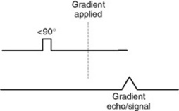
GRADIENT ECHO (GE) SEQUENCE
Gradient echo scans are very different to a spin echo sequence. A smaller RF pulse produces a small flip angle of less than 90 ° and, instead of another RF pulse, a magnetic gradient is then applied (Fig. 19.8).
PULSE SEQUENCE FACTORS
IMAGE WEIGHTING
T1 WEIGHTED SPIN ECHO OVERVIEW
A T1 SE sequence, for example, could be achieved with a TE of 15 ms and a TR of 600 ms.
T2 WEIGHTED SPIN ECHO OVERVIEW
So a T2 SE sequence, for example, could be achieved with a TE of 102 ms and a TR of 3000 ms.
INTERPRETING IMAGES
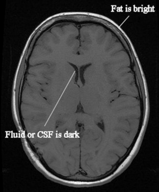
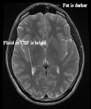
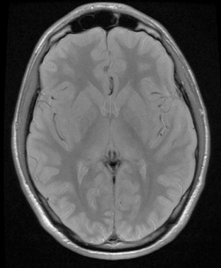
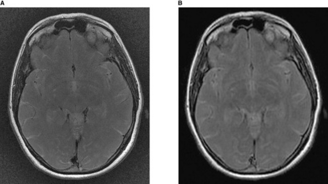
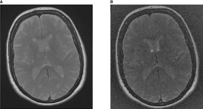
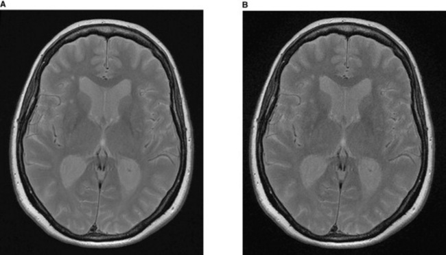
For example, on a T1 SE weighted scan, fat looks bright white and water dark black – so the fat in the scalp is seen as a bright area and the ventricles of the brain, which contain cerebrospinal fluid (CSF), look dark because CSF is a fluid like water (Fig. 19.9). On the T2 FSE weighted scan the opposite is seen – the fat is now darker and the fluid bright (Fig. 19.10). A PD scan looks at just the density of hydrogen protons and produces a very grey image that effectively is a proton density map (Fig. 19.11).
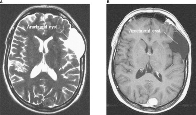
The pathology shown in Figure 19.12 looks bright on T2 and dark on T1 so implies the lesion is made primarily of fluid. This is the case and the radiologist can suggest an arachnoid cyst as the likely diagnosis. So the radiologist can make accurate diagnoses knowing how differenttissues and pathologies look on different image weightings.
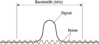
SIGNAL-TO-NOISE RATIO
FACTORS AFFECTING THE SNR
ARTEFACTS
PHASE WRAP
Phase wrap is when an area of anatomy outside of the field of view is mapped (or wraps) inside the image. This occurs along the phase encoding direction. Changing the phase encoding direction or using the ‘no phase wrap’ option on thescanner can remedy this. In Figure 19.19 the nose is wrapped around the image and is now on the back of the head, not the front.
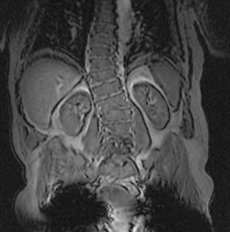
PHASE MISMAPPING
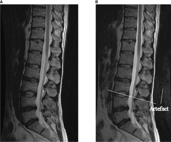
Another remedy is to use a saturation band to nullify the signal from the moving anatomy. For example, when imaging the lumbar spine an artefact can occur across the spinal cord from the moving contents of the abdomen. If a presaturation pulse/band is placed in front of the spinal column covering the abdominal contents, the artefact on the image is reduced (Fig. 19.20).
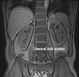
CHEMICAL SHIFT ARTEFACT
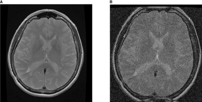
Chemical shift artefact is caused by the different precessional frequencies of fat and water. Precessional frequency is proportional to the strength of the main magnetic field. At low field strengths the difference between the precessional frequencies is not great, but at high field strengths the difference is enough to cause chemical shift artefact. An example is shown in Figure 19.21.
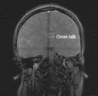
CROSS-TALK
Cross-talk, or cross-excitation, occurs when the RF excitation pulse in an adjacent slice excites protons in the slice being scanned. To reduce the effects of this artefact it is best to keep a gap between slices of about 10% and try not to cross slices. An example of cross-talk is shown in Figure 19.22; the dark band across the image is where the cross-excitation has occurred.
MAGNETIC SUSCEPTIBILITY ARTEFACT
Magnetic susceptibility artefact is caused by the ability of a substance to become magnetised. The degree to which it becomes magnetised results in a difference in phase and precessional frequency and there is signal loss or void on the image. This primarily happens with metal. A patient who has a metal implant in the area being scanned will have images with magnetic susceptibility artefact. If at all possible the metal should be removed, but in the case of a metal prosthesis fixed within the body the only option is to choose pulse sequences that are less susceptible to this type of artefact. In general, SE sequences are less susceptible than GE sequences. An example of signal void or magnetic susceptibility is shown in Figure 19.23; there are black signal voids where this patient’s hips should be due to his bilateral hip replacements causing magnetic susceptibility artefact.
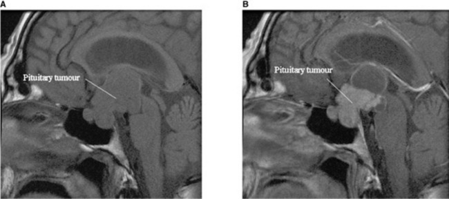
MRI CONTRAST AGENTS
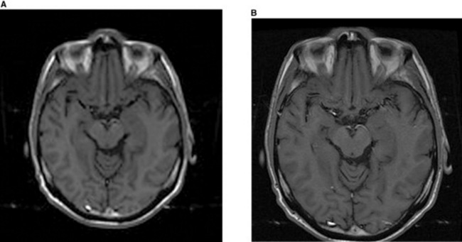
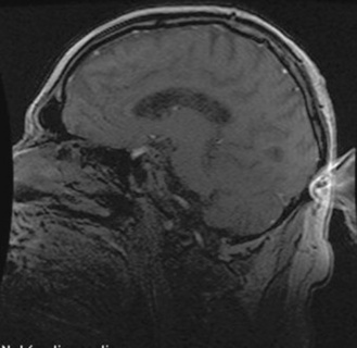
The administration of gadolinium affects the T1 recovery of tissue and shortens its T1 recovery time. On T1 weighted scans areas of contrast enhancement will appear bright white on the image. Contrast agents are taken up by tissues with an enriched blood supply (e.g. tumours and sites of infection). Some pathology has very characteristic patterns of contrast enhancement; for example, brain abscesses ring enhance and meningiomas tend to have uniform enhancement. The administration of contrast can therefore aid the radiologist with making a diagnosis. Because some tissues appear bright on a T1 weighted scan without the administration of gadolinium (e.g. fat) a T1 weighted scan is performed pre and post the administration of the contrast. The pre contrast image can then be compared to the post contrast image to see which tissues are really enhancing (Fig. 19.24).
MRI SAFETY
The most important issue when undertaking MRI scanning is MRI safety. This point cannot be emphasised enough. To reiterate, the magnetic field is present 24 hours a day, 7 days a week, 365 days a year, even when the scanner is not performing a scan and is silent. All personnel and patients entering the MRI scan area should complete an MRI safety questionnaire. Every MRI unit will have their own safety form but it will cover the same main safety issues (Fig. 19.25). Most MRI safety issues relate to the main magnetic field and the time varying magnetic field (the switching of gradients and RF pulses during scanning).

METAL OBJECT REMOVAL
All metal objects need to be removed from everybody (including radiographers, patients anddoctors) before entering the MRI scan room. This includes coins, keys, scissors, stethoscopes, hair clips, cigarette lighters, etc. The list is endless, so the safest thing is to remove everything; some units even require all patients to wear only a hospital gown to stop anything metal being accidentally overlooked. Other objects like bankcards or mobile phones need to be removed because although they might not be attracted to the magnet the magnetic strip on the cards will be wiped and the components of the phone ruined.
IMPLANTS
NOISE
Having an MRI scan is a very noisy procedure. The magnetic field itself is silent, and when the scanner is not scanning a soft ‘chirping’ sound in the scan room is heard, which is the compressor pumping the liquid helium around the scanner. However, when the scanner is performing a scan the noise is literally deafening. The noise is the magnetic gradients switching very quickly. All patients and personnel who remain in the scan room have to wear ear protection. Earplugs are perfectly adequate for the job but most modern scanners have a stereo system attached to some MRI compatible headphones so the patient can listen to music whilst also protecting their ears.
QUENCHING OF THE MAGNET
If the worst happens and a metal object does enter the scan room, is stuck to the magnet and cannot be pulled off, the only way to extricate it is to remove the main magnetic field. To do this the magnet has to be quenched. There is a button in every MRI scanner to quench it. It is usually underneath a protective cover so that it does not get pressed by accident. When the quench button is pressed it very quickly releases all the helium in the scanner. It should be vented through a pipe from the scanner to the outside world. The magnetic field will then collapse so the object can be removed from the scanner. The release of the helium can also cause problems; for example, if there is a blockage in the pipe, the helium will enter the scan room, suffocating anyone inside – all MRI units should be fitted with an oxygen sensor that will set off an alarm if such an event happens. On hearing the alarm all personnel should be evacuated from the scan room. Quenching is something that should only be done in anemergency or life-threatening situation because the magnet can be damaged due to the heat generated in the coils and the cost of replacing tens of thousands of litres of liquid helium is expensive.
ADVANCED TECHNIQUES
There are many advanced techniques that can be performed on an MRI scanner. A few of these are
Marieb EN. Human anatomy and physiology, 3rd edn. California: Benjamin/Cummings, 1995.
Moses KP, et al. Atlas of clinical gross anatomy. Philadelphia: Elsevier Mosby, 2005.
Thibodeau GA, Patton KT. Anatomy and physiology, 5th edn. Missouri: Elsevier Mosby, 2003.
Van Wynsberghe D, Noback CR, Carola R. Human anatomy and physiology, 3rd edn. New York: McGraw-Hill, 1995.
Waugh A, Grant A, Ross, Wilson. Anatomy and physiology in health and illness, 9th edn. Edinburgh: Elsevier, 2002.
Westbrook C, Kaut Roth C, Talbot J. MRI in practice, 3rd edn. Oxford: Blackwell Publishing, 2005.
This text provides a clear introduction to MRI. The text is well laid out with clear diagrams..
Westbrook C. MRI at a glance. Oxford: Blackwell Science, 2002.
This provides clear, concise information on MRI physics..
McRobbie DW, Moore E, Graves M, Prince M. MRI from picture to proton, 2nd edn. Cambridge: Cambridge University Press, 2007.
Waugh A, Grant A, Ross, Wilson. Anatomy and physiology in health and illness, 9th edn. Edinburgh: Elsevier, 2002.


