[level-membership-for-cardiovascular-category]
22 Left Ventricular Lead Implantation
Cardiac resynchronization therapy (CRT) reduces the chance of hospitalization, improves quality of life, and lowers mortality from congestive heart failure.1–4 CRT requires left ventricular (LV) pacing, usually by a lead placed transvenously through a coronary vein on the epicardium.5–7 Transvenous pacing of the LV epicardium through the coronary venous system can be technically difficult,2,8 but it is safe, and thresholds remain stable.7,9
Transvenous LV lead implantation was new in 1998 and, as with most new therapeutic procedures, required the development of tools and techniques for its safe and cost-effective implementation into clinical practice.10 Because CRT devices were implanted predominantly by electrophysiologist (EP) physicians, their skill set and experience determined the initial tool set. Unfortunately, the EP-suited tools did not overlap well with those useful for LV lead implantation, resulting in a steep learning curve, long case times, and failed implants. Using the EP skill set, pioneering physicians and early adopters eventually developed their own technique, employing a combination of the limited tools designed for the procedure and existing tools that proved useful through improvisation;11–20 however, some patients experienced adverse results.21–25
 Overview
Several notable developments have occurred since the last edition of this textbook. Electronic repositioning in conjunction with bipolar leads (soon to be multipolar leads) has greatly improved success.26 The most important development involves delivery systems.27,28 Telescoping guide support–based delivery systems employ sliceable, preshaped guides for insertion through a separate coronary sinus (CS) access catheter that delivers leads directly to the target vein, allowing for interventional techniques.29,30 Optimal use requires the physician to learn and apply such principles as safe use of contrast, manipulation of open-lumen catheters, effective and efficient injection of contrast, and importance of table position.31
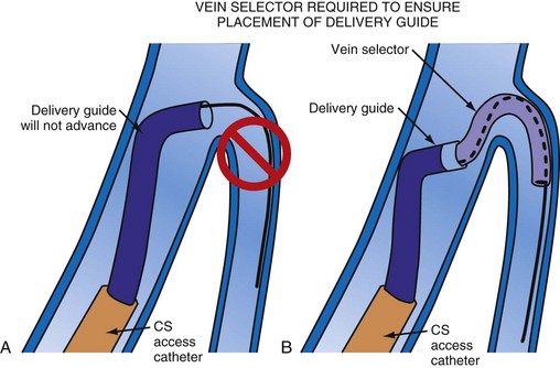
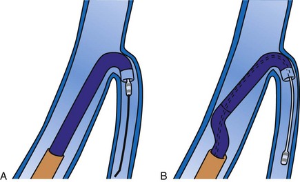
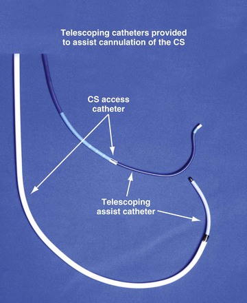
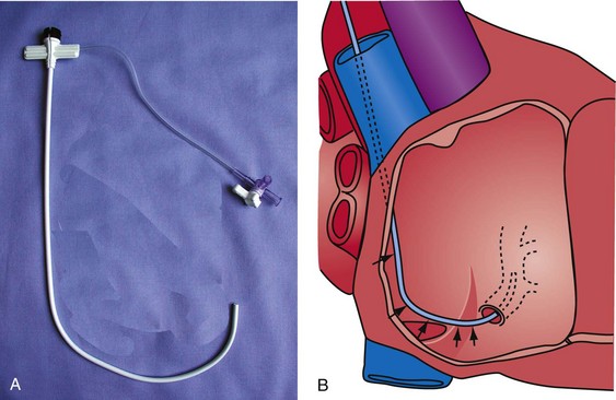
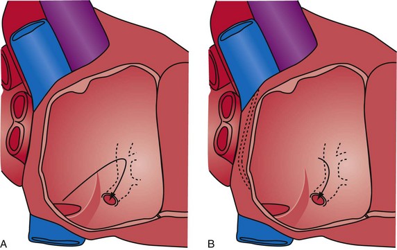
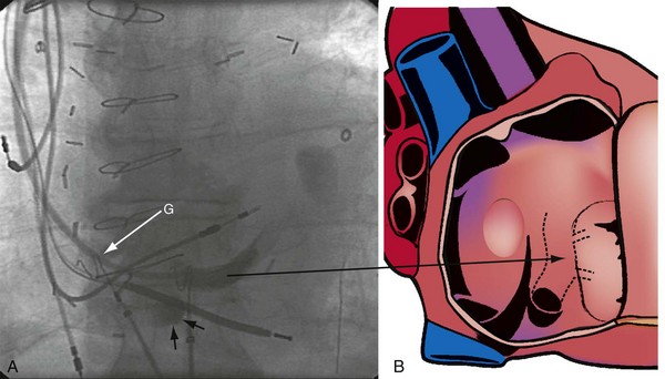
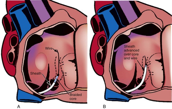
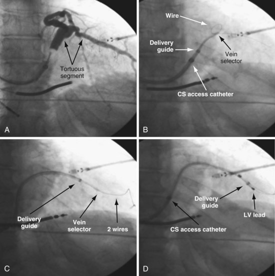
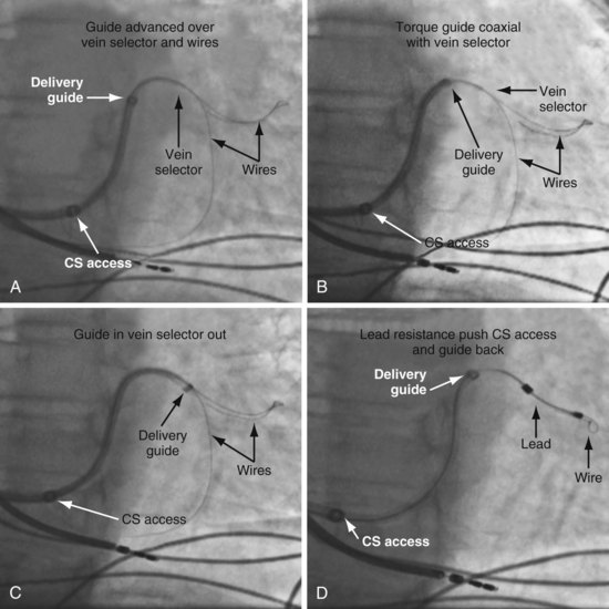
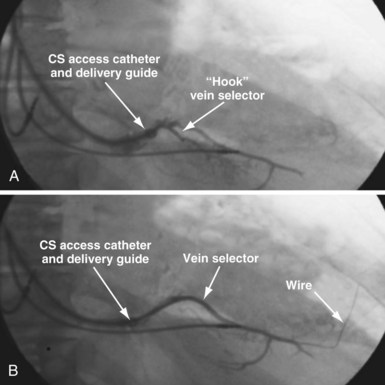
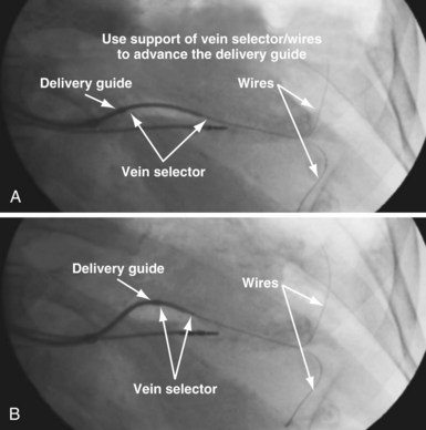
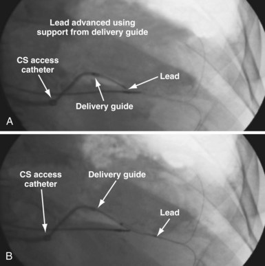
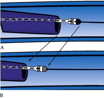
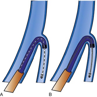
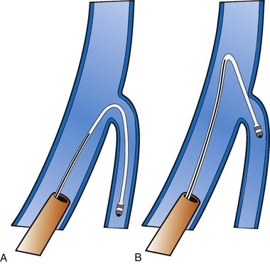
Although an important advance, the new guide support–based delivery systems have two limitations: (1) most do not offer a delivery guide for leads with diameter of 6 to 7 French, and thus only leads 5 Fr (5F) or less usually are deliverable, and (2) most lack a vein selector. A vein selector serves two functions. First, it locates and cannulates the target vein. The design parameters required for a delivery guide, however, limit the ability to locate and cannulate the target vein. It is easier and safer to use a small catheter with a flexible tip to locate the target vein than a catheter designed to provide support for lead delivery. Second, the vein selector provides a rail for the delivery guide. Once the delivery guide locates the vein, it may not be possible to advance into the vein. If a small, flexible-tip catheter is telescoped into the vein through the delivery guide, it can be used as a rail to ensure the tip of the guide engages the vein. The small catheter with a flexible, tapered tip that telescopes through the delivery guide to locate the vein, then act as a rail over which to advance the guide, is a “vein selector” (Fig. 22-1).
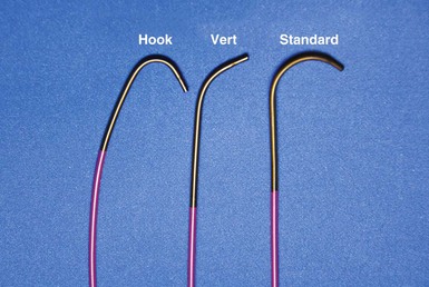
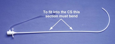
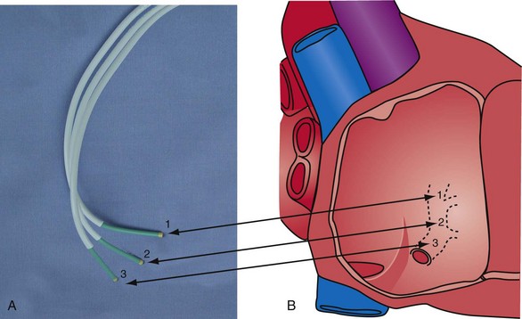
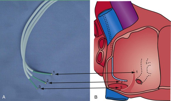
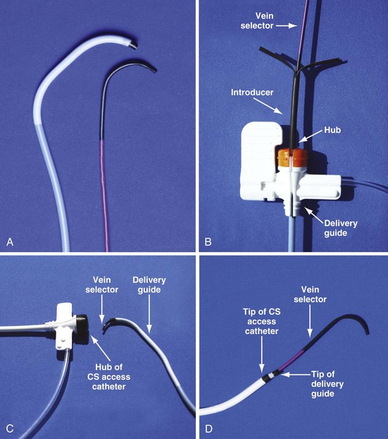
Although catheters from interventional radiology and cardiology can be used as vein selectors, they are the wrong length, the tips are too stiff, and the shapes are not ideal (Fig. 22-2). Fortunately, additional vein selectors are now available in multiple shapes (Fig. 22-3).
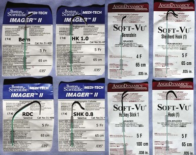
Figure 22-2 Variety of shapes used to locate and cannulate target veins over last decade.
(Courtesy Boston Scientific and AngioDynamics.)
Definitions
Philosophical Approach
This chapter employs the mindset that left ventricular lead implantation should use the most effective tools and techniques to succeed with a transvenous approach. Often this requires tools supplied by more than one vendor and multiple techniques. This approach puts the welfare of our patients first and increases the responsibility of the implanter. If the traditional transvenous approach fails, one option is transseptal, an approach that can be technically difficult and associated with the risk of thromboembolism.32 However, recent studies found a superior hemodynamic performance associated with endocardial compared with epicardial stimulation,33 possibly by allowing access to previously inaccessible pacing sites.34 Our experience in four patients who declined a surgical lead is favorable. Chapter 23 provides a more detailed discussion of transseptal LV lead placement.
Surgical epicardial LV lead placement is covered in the final section of this chapter. Although the surgical approach is an easy way for the implanting physician to complete the procedure,35 “the importance of maximizing the use and safety of transvenous approaches is stressed because while the electrical and functional limitations of trans-CS LV epicardial coronary vein leads are well publicized, the limitations of available transthoracic, transepicardial, and true epicardial electrodes may be less appreciated,”36 with 15% LV lead failure at 5 years.37 In addition to lead failure, lead position, morbidity, and mortality must be considered. Utilizing pressure-volume loops, Dekker et al.38 found epicardial sites that “did not significantly change left ventricular function and even worsened it in some cases.”38 If surgical placement is attempted, the surgeon needs the same dedication as the implanting physician to place the LV lead in the appropriate location with good thresholds.
Although data are limited, without a prospective randomized comparison, complications and mortality appear to be much higher than the transvenous approach.39–41 In the series by Ailawadi et al.,39 the mortality was double, and postprocedural complications of acute renal injury (26.2% vs. 4.9%; P < .001) and infection (11.9% vs. 2.4%; P < .03) were more common in the surgical group. Based on analysis of the Replace Registry, surgical LV lead mortality may be greater than 8%; 48 patients (11% of 434 attempted LV lead placements) had a failed EP lab attempt. There were four deaths in the patients sent for surgical epicardial LV placement. Assuming every patient with a failed attempt went to surgery for an epicardial lead, the mortality is 8%.40 However, we do not know how many of the 48 were actually sent for an epicardial lead, or if the patients who required surgical intervention were similar to those who did not.
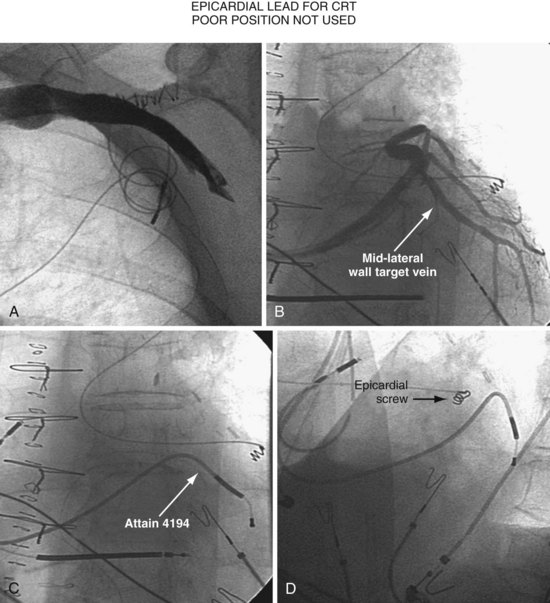
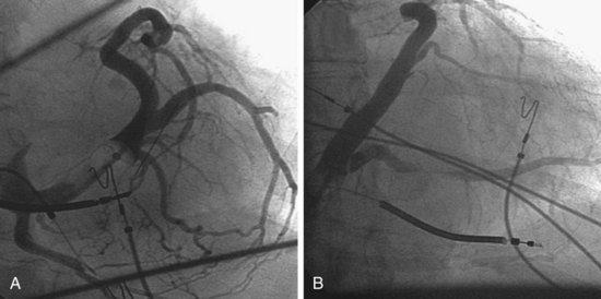
Figure 22-4 is from a patient who underwent lead placement through an epicardial approach, showed no response, and then experienced improvement with a transvenously placed lead. Figure 22-5 contains the lateral chest radiographs of three patients who had failed transvenous implants, then did not respond to an epicardial lead, but improved when a lead was placed transvenously using guide-based delivery system and interventional techniques. If the patient is to be exposed to surgical risk, it is important to insist that the surgically placed leads are located on the midlateral free wall.
 Left Ventricular Lead Position and Response
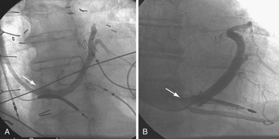
As mentioned earlier, not only does cardiac resynchronization therapy require pacing of the left ventricle, but the location of the lead can be important as well.38,42 The midlateral wall of the left ventricle usually is the best location for an LV lead. When considering whether a patient is not responding to CRT, lead position can be important. The left anterior oblique (LAO) view on fluoroscopy at implantation should define the LV lead position. However, if the fluoroscopy is not performed in a standard manner, it can be deceptive. Kistler et al.43 describe a case in which electrocardiographic analysis showed that a lead fluoroscopically thought to be in the left ventricle at implantation was actually in the right ventricle.
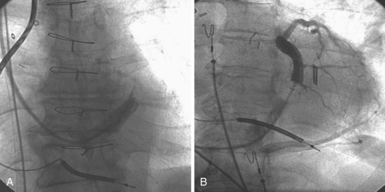
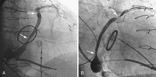
Another example of fluoroscopic error is shown in Figures 22-6 and 22-7. The LAO fluoroscopic image in Figure 22-6, A, appeared to document a lateral position. However, the lateral chest radiograph demonstrated the anterior location (Fig. 22-6, B). In Figure 22-7, A, the steeper LAO projection reveals the anterior nature of the first (“nonresponder”) LV lead position. It is important for the implanting physician to take personal responsibility for reviewing the final location of the LV lead, to ensure that the patient has received the best possible lead position. In follow-up of patients after implantation, we demonstrated that the left ventricular (LV)–right ventricular (RV) lead separation on the lateral chest radiograph is essential in evaluating “nonresponders” in whom LV lead placement has been “successful.”44 Heist et al.45 demonstrated that the acute hemodynamic effect of CRT is predicted by the LV-RV interlead distance, as measured on the lateral chest radiograph after the procedure. Placement of the LV lead on the anterior surface of the left ventricle is at best suboptimal, resulting in deteriorating LV function in some patients regardless of the method of implantation.38 Unless convincing, specific information to the contrary is available, the midlateral free wall of \the left ventricle appears to be the optimal position for the LV lead. When the LV lead is on the midlateral wall, its position on a lateral chest radiograph is directly posterior. Figure 22-8 shows the typical postimplantation chest radiographs of a “responder” in whom the LV lead is located on the midlateral wall of the left ventricle. Note that the LV and RV leads are maximally separated on the lateral chest radiograph.
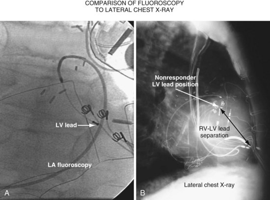
Figure 22-6 Fluoroscopy and chest radiography at initial implantation of left ventricular (LV) lead.
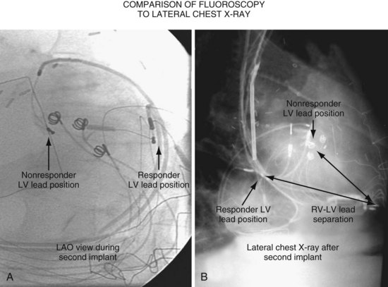
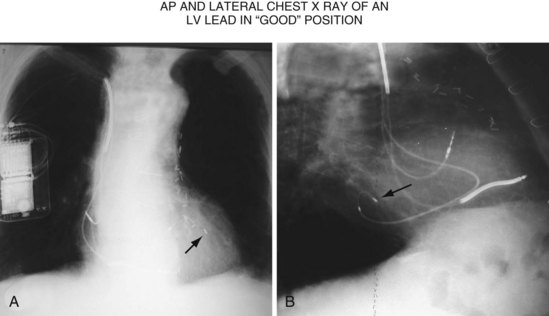
Figure 22-8 Chest radiographs of patient showing response to cardiac resynchronization therapy (CRT).
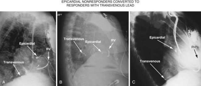
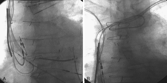
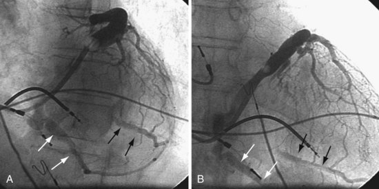
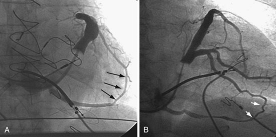
Figure 22-9 includes the lateral chest radiographs of two patients who showed no response to CRT with their original lead position but did respond when a lead was positioned on the midlateral free wall. Figure 22-9, A, is the lateral chest radiograph of a nonresponder in whom the lead was placed in the anterior interventricular vein; patients with a lead in this location are not expected to show response. Figure 22-9, C, however, is the lateral chest radiograph of a patient who showed no response even though the LV lead had been placed in the vein to the midlateral free wall. What happened? The LV lead is advanced distally in the midlateral vein, which wraps around anteriorly toward the septum. Although the lead started in the vein to the midlateral free wall, it ended up anterior, close to the RV lead. Note that in Figure 22-9, A and C, the tip of the LV pacing lead is closer to the RV pacing lead than the ideal position seen in Figure 22-8, B. When a second LV lead was placed, this time on the lateral wall (Fig. 22-9, B and D), the patients improved clinically and were regarded as “responders.”
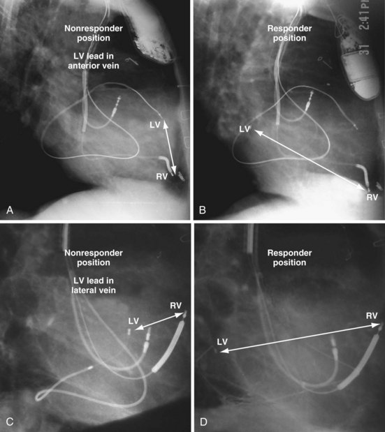
Figure 22-9 Chest radiographs of CRT nonresponders versus responders.
A, Anterior left ventricular (LV) lead is in the anterior vein. B, New lead is placed in a lateral vein, converting a CRT nonresponder to a responder. C, The lead starts in the lateral wall target vein but is advanced distally, which places the tip anterior (not apical) well beyond the ideal location. In both A and C, the physical separation between the right ventricular (RV) and LV leads (white arrows) is small. In both patients, new leads were placed (B and D) in positions similar to those shown in Figure 22-8, with marked improvement in symptoms. In the patient in C and D the new LV lead was placed more proximal in the same vein.
The clinical question raised is whether repositioning the LV lead of the patient in Figure 22-9, C, to a more proximal position in the same vein, thus increasing the RV-LV separation, would change a nonresponder to a responder. Figure 22-10 illustrates the original and new, more proximal positions in the same vein of a patient in whom such repositioning was performed. The RV-LV lead separation was increased, and the patient demonstrated a marked symptomatic improvement, objectified by reductions in both serum creatinine level and dose of diuretics.
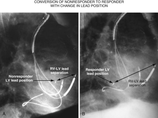
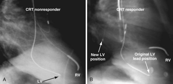
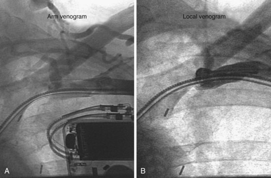
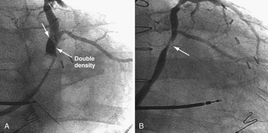
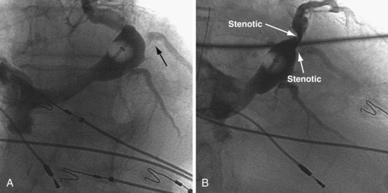
Figure 22-11, A, is the lateral chest radiograph of a patient in whom the original implanting physician was not prepared to perform coronary vein venoplasty. The vein to the midlateral wall was distal to a stenosis in the main body of the CS. Although the implantation was regarded as “successful,” the pacing lead was not placed on the midlateral wall of the left ventricle. The patient did not improve after the procedure, was regarded as a CRT “nonresponder,” and listed for heart transplantation. He was evaluated at our facility, where the lead position on the lateral chest radiograph was discovered. He subsequently underwent venoplasty of the main body of the CS, and the lead was placed on the lateral wall of the left ventricle (Fig. 22-11, B); dramatic resolution of symptoms eliminated the need for a heart transplant. Both the acute hemodynamic effect and the subsequent clinical response to CRT are predicted by the RV-LV lead separation on the lateral chest radiograph. On the basis of the work of Heist et al.,45 the RV-LV separation in the horizontal plane is more important than the total RV-LV separation, and the RV-LV separation in the vertical plane was not predictive.
 Guide Support–Based Delivery System
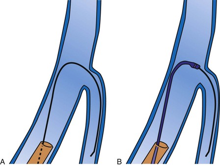
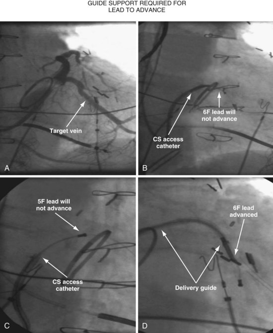
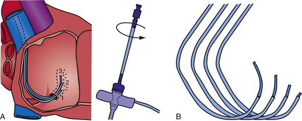
Since 1997, LV pacing leads have evolved from unipolar 6F stylet-driven to quadripolar 5F over-the-wire leads. Despite improvements in LV pacing leads, their placement continues to be limited by the coronary venous anatomy. Frequently, guide support is required because the angioplasty wire does not provide adequate support to advance the LV lead into the vein (Fig. 22-12). Guide support is present when the tip of the guide rests securely within the target vein and the back of the guide is supported by the coronary sinus, as occurs with a catheter where the tip is preshaped specifically to cannulate the target vein, not the CS. The magnitude of support provided by the preshaped guide depends on its shape, as shown in Figure 22-13; the compound shape in B offers greater support than the single curve in A because the secondary curve is supported by the CS back wall.
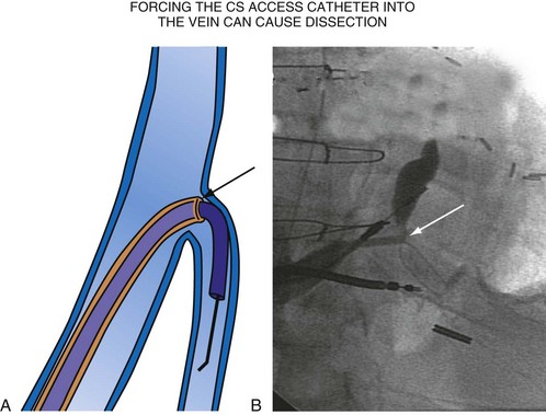
For the purposes of this chapter, a delivery guide is defined as a braided, slittable catheter preshaped for LV lead delivery (not for CS access) that is inserted through a separate catheter in the CS. A CS access catheter is defined as a removable catheter designed specifically for CS cannulation and to provide a platform for LV lead delivery. CS access catheters can occasionally provide guide support when it inadvertently cannulates the target vein or is forced into the vein. Forcing a CS access catheter requires an angle of less than 30 degrees, a situation where guide support is usually not required. Furthermore, the potential exists for dissection as the straight tip of the CS access catheter is forced around the curve (Fig. 22-14).
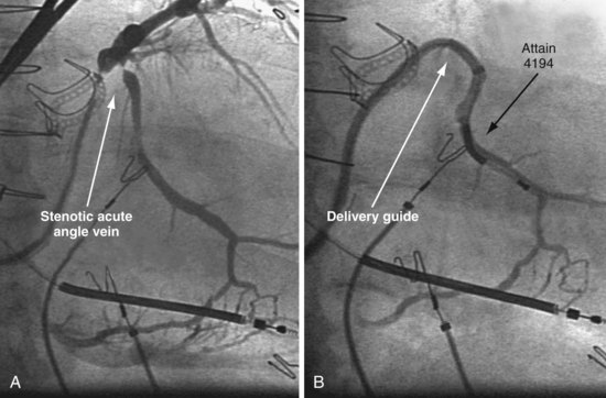
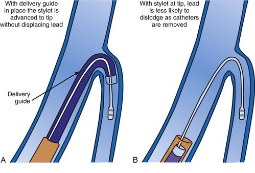
A delivery guide is the most reliable way to deliver a lead to the target vein, particularly when the anatomy is difficult (Fig. 22-15), but also even when the anatomy seems favorable (Fig. 22-16). In addition, the delivery guide makes it easier to deal effectively with lead instability, high thresholds, and phrenic pacing; inject contrast to identify branches; provide support to reposition the lead; or change to a lead of different size or shape and to a different method of fixation. Lastly, because the delivery guide allows the stylet to be safely advanced to the tip (Fig. 22-17), the final step of removing catheters from the CS is less likely to displace the lead. Accordingly, the approach to LV lead implantation described in this chapter is based on using a guide support–based delivery system.
Shape and Use of Delivery Guides
Previous Approach
In the third edition of this book, I emphasized matching delivery guide shape to the target vein anatomy for two reasons. First, at that time we used either interventional guides from radiology or the first-generation Pressure Products delivery guide (Fig. 22-19, A). Both had very firm tip sections, which could not be advanced into the target vein or did not remain stable once advanced (Fig 22-20). However, with the new soft-tip design (Fig. 22-19, B), the Pressure Products delivery guide can be advanced deep into the target vein and remains stable.
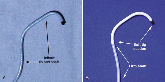
Figure 22-19 Comparison of tip section of original and current delivery guides.
(Courtesy Pressure Products, San Pedro, Calif.)
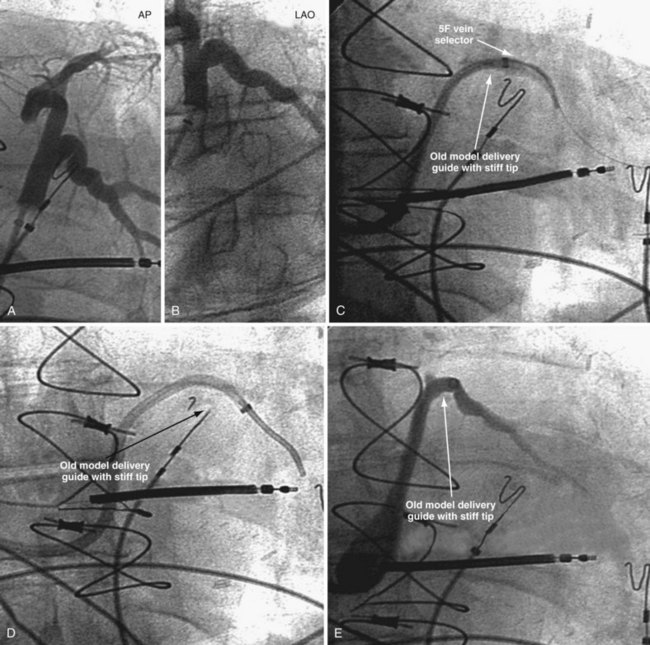
Figure 22-20 Stiff tip prevents secure advancement of interventional and delivery guides into target vein.
Second, it initially appeared that the delivery guide could be used reliably to locate the vein, advance the wire, and then be advanced over the wire into the vein. Although effective in some cases, we found that the delivery guides were not optimal for small or off-axis target veins, necessitating the addition of a small, diagnostic catheter telescoped through the delivery guide (see Fig. 22-1). It thus became clear that a small diagnostic catheter (vein selector) was an essential component of a guide support–based delivery system and needed to be included with the delivery guide (see Fig. 22-3).
New Approach
Recognizing that a vein selector will be needed to locate and cannulate the target vein in at least some cases, and that the soft tip of the new Pressure Products delivery guide can be advanced to a stable position deep in the vein if needed, we now rely on the shape of the vein selector for off-axis and difficult veins and use a single shape of delivery guide. Using the included vein selector and wire(s) as a rail the “renal” delivery guides can be inserted into the vast majority of target veins, regardless of takeoff (Fig. 22-21). We rarely if ever use one of the other shapes of Pressure Products delivery guides (hook, hockey stick, or multipurpose). The vein selectors also work in the same manner with the device company delivery guides.
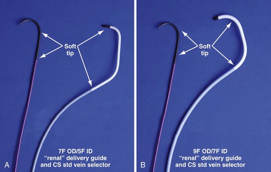
Figure 22-21 Renal-shaped delivery guides with vein selector.
A, The 7-French (7F) “renal” delivery guide is shown with the included 5F standard vein selector (Telescopic Braided Renal LVI 75-5-66-55-RE, Pressure Products). It has a 7F outer diameter (OD), 5.5F inner diameter (ID), and a working length of 66 cm. B, The 9F OD renal delivery guide is shown with the included 5F standard (std) vein selector (Telescopic Braided Renal LVI 75-5-62-07-RE). It has a 9F OD, 7F ID, and working length of 63 cm. The soft tip section of the delivery guide can be advanced deep into a target vein over the vein selector, if needed. As a result, we now rely on the shape of the vein selector, not the shape of the delivery guide, to accommodate the takeoffs of various veins. When used with a vein selector, the renal-shaped delivery guide is suitable for the vast majority of cases. In approximately 10% of cases, one of the other two vein selectors (Impress CS Vert p/n 1628-017 or Impress CS Hook p/n 1628-019, Merit Medical; see Fig. 22-3) may be required to locate and cannulate the target vein.
 Left Ventricular Lead Implantation with Interventional Techniques
Step-By-Step Summary
Details and Rationale
This section describes my recommendations for implanting LV leads and the tools used. Chapter 23 describes more advanced interventional technique, including crossing total occlusions, subclavian and coronary vein venoplasty, using balloons as anchors, and use of snares. With these techniques, we have successfully implanted all 27 patients with failed implants referred from other centers, including five who had epicardial leads but did not respond.
Prepare Patient for Iodinated Contrast Material
The safe use of contrast is discussed in detail in Chapter 23. In summary, contrast improves safety, reduces implant time, and is essential to the use of a guide support–based delivery system. Rather than only trying to limit contrast, it is better to take steps to prevent nephropathy. Use of contrast can then be individualized; many patients will be at relatively low risk, whereas others (e.g., diabetics with increased creatinine) remain at high risk. Because the serum creatinine can vary substantially in CRT patients depending on volume status, we recommend hydration for all patients as follows:
Equipment and Room Setup
Collect Available LV Lead Implantation Equipment and Review Its Use
The worst mistake may be to assume that the equipment required for a successful efficient LV lead implantation either is in the room or has been provided by the manufacturer. Some of the equipment is readily available in the hospital but is not part of the usual repertoire of many implanting physicians. Knowledge of the equipment used in interventional radiology and interventional cardiology can be extremely useful during an LV lead implantation (see Interventional Implant Equipment List at end of chapter). The technical staff and physicians from interventional cardiology and radiology often have helpful suggestions for solving the mechanical problems posed by an LV lead implantation, and equipment specifically tailored to LV lead placement is slowly making its way into the world of electrophysiology. Access to these new tools can make the difference between an easy success and a painful, demoralizing failure.
Organize Equipment to be Readily Available in Room
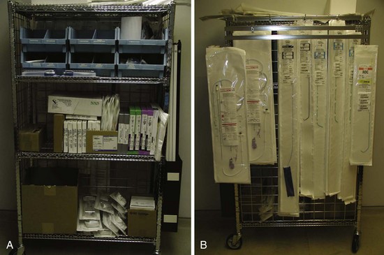
It is important to remember that the interventional implant equipment needed is not usually available in a room used for either pacer implantation or an EP study. To avoid spending more time surveying the interventional cardiology and radiology laboratories than actually working on the patient, the physician should make certain of having the most basic equipment in the room. These tools are additional to the device company equipment and sheaths used for pacemaker implantation. To be certain we have the proper tools regardless of the room, our staff created a “BiV Cart.” This cart also contains equipment for performing subclavian and coronary vein venoplasty (Fig. 22-22).
Assemble “Always Used” Equipment on Table before Starting
Having a routine and setting the table with equipment needed for the procedure give the operator the freedom to concentrate on the procedure and help avoid “rethinking” the tools for each implantation (Fig. 22-23).
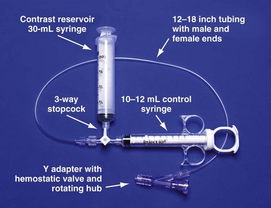
Figure 22-23 Simplified system to allow assistant to inject contrast while operator manipulates catheter with both hands.
For right-handed operator, the right hand is on the rotating hub on the Y adapter, and the left hand is on the catheter. The system is used to inject contrast for location of the coronary sinus os, for the occlusive venogram, and for locating the target vein with the vein selector. The system can be constructed from equipment readily available in most laboratories and is available as a kit (Pressure Products or Merit Medical; see equipment list at end of chapter for details). The scrub technician should have the pieces on the table and assembled before notifying the implanting physician to scrub for surgery.
Pay Careful Attention to Orientation of Instrument Table During Procedural Stages
It is remarkable how important the position of the instrument table can be to a successful implantation. It is even more remarkable how frequently even an experienced implanter forgets to change to a table position appropriate to the stage of the procedure until either the support staff provides a gentle reminder or something that should be easy feels difficult. Figure 22-24, A, demonstrates the usual “backfield” position of the instrument table. We keep the table in this position until we start CS access, at which point the table is turned perpendicular to the patient (Fig. 22-24, B). Once the LV lead is in place and it is time to start removing the guide and sheath, the table is returned to the backfield position so the assistant can support the sheath and lead during sheath and guide removal.
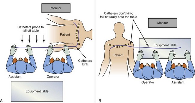
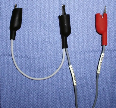
The custom-built table shown in Figure 22-25 addresses all three issues. The legs are recessed to provide room for the fluoroscopy unit, the operator’s feet, and fluoroscopy pedals. The height is adjustable so that the top of the table can be raised to reduce the vertical stepoff between the patient and the table. Interventional principles teach that when working with catheter, it is important that the implant table be turned perpendicular to the patient table (T-bone position) so that the wires and catheters exit the body falling naturally onto the table (see Fig. 22-24, B). Further, the assistant is in the optimal position to assist with the catheter manipulation, contrast injection, and wire exchanges required for LV lead implantation and the use of balloons. Application of torque to the catheters is not lost in a right angle, and the open-lumen catheters are not prone to kink. Testing the left and right ventricles simultaneously for pacing thresholds can be difficult with standard testing cables. Simply attaching an additional alligator clip eliminates this problem (Fig. 22-26).

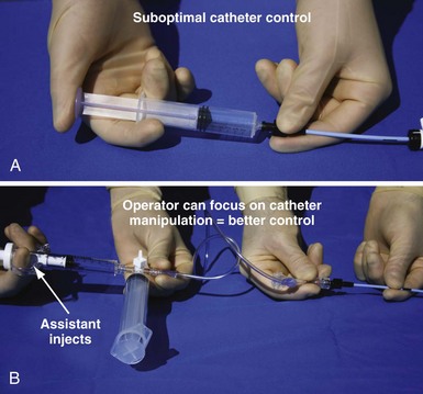
Approach to Contrast
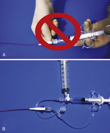
An important point frequently overlooked is the approach to contrast injection. EP physicians accustomed to working alone with solid catheters naturally try to inject contrast and control the catheter. However, interventional principles clearly show that catheter control is degraded when one hand is removed from the catheter and attention is turned to contrast injection. Suboptimal catheter control will result in increased use of contrast and a greater chance of misadventure. For optimal catheter control, the operator keeps both hands on the catheter and attention focused on tip position (Fig. 22-27).
Venous Access
Preventing Restricted Catheter/Lead Movement
Separate Access for Each Lead
Having separate access sites for each lead reduces the interaction among the three leads. If only two access sites can be obtained, the RV and RA leads should be placed through the same access site to minimize the potential for movement of either lead to displace the LV lead. When leads share the same access, friction between the two may result in the stable lead being withdrawn by manipulation of the other lead. To help prevent lead withdrawal, keep the stylet of the stable lead at the junction between the inferior vena cava (IVC) and superior vena cava (SVC) until manipulation of both leads is complete, even after the stable lead is tied down. Without a stylet, the stable lead can withdraw, even when tied to the muscle, by forming an S configuration within the subclavian vein distal to the tie-down (Fig. 22-28).
Response to Subclavian Obstruction in Patient with Preexisting Leads
In about 20% to 30% of patients with previously implanted leads, one or more stenotic areas will develop between the site of venous insertion and the right atrium (Figs. 22-29 to 22-32). Before the advent of LV lead placement, the response of the implanting physician to a subclavian stenosis was to go to the other side or to advance progressively larger dilators until the sheath could be advanced. Dilator opening of a stenotic area, if possible, is always incomplete. The stenotic area continues to restrict wire and catheter manipulation, making LV lead placement much more difficult if not impossible; also, distal stenotic areas are not addressed. Venoplasty safely creates much less restricted access than progressively larger dilators and can address a central stenosis (see Figs. 22-31 and 22-32). Details of how to deal with a subclavian occlusion is discussed in detail in Chapter 23.
Platform for Lead Placement
Lumen Size
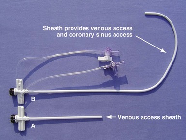
The platform available for LV lead placements starts with the choice of venous access for the LV lead. Typically, short peel-away sheaths are used to access the venous circulation for insertion of leads in the right atrium and right ventricle (Fig. 22-33, A). When the CS access catheter is an 8F to 9F OD guide provided by the device company, venous access is obtained with a short, 9F sheath. This results in a 7F ID access to the coronary sinus. The small-caliber CS access limits the use of a guide to one that only delivers 5F or smaller leads. By comparison, when the sheath in Figure 22-33, B, is used for venous access, it is also the CS access catheter; thus a 9F ID lumen is available in the CS. The larger-caliber CS access alloys the use of guides that can deliver up to 7F leads. Long, peel-away sheaths are used for both venous and CS access (Fig. 22-34, A).
Catheter Shape
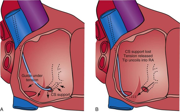
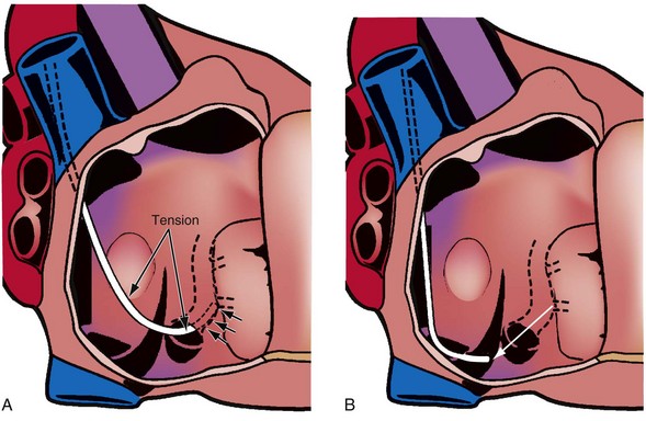
The shape of the CS access catheter determines the support provided. If not anatomically shaped, the catheter must be deformed from its original shapes to fit the cardiac anatomy. The deformed catheter is under tension and prone to dislodge from the CS. The anatomically curved catheter not only is stable in the CS but provides support during LV lead placement from contact with the lateral wall and floor of the right atrium and eustachian ridge (Fig. 22-34, B).
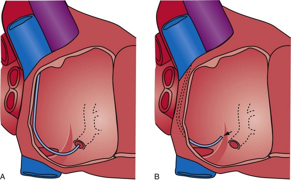
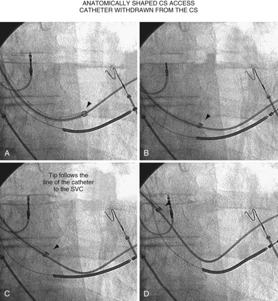
The shape of the CS access catheter determines whether it is likely to displace the lead as it is removed from the CS. A deformed CS access catheter under tension while in the CS loses its support as it is withdrawn and suddenly resumes the original shape, directing its tip to the floor of the right atrium, a movement that may pull the lead out of the target vein (Fig. 22-35). By comparison, an anatomically shaped catheter is not under tension as it rests in the CS. When removed, the tip of such a guide rises above the CS (Fig. 22-36).
Cutting versus Peeling to Remove
Why Peel-away Sheaths Are Not Provided for CS Access
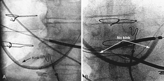
When CRT first began, the device companies offered long, peel-away sheaths but quickly switched to braided, sliceable catheters because (1) peel-away sheaths did not have the torque control required for reliable CS cannulation, and (2) the peel-away sheaths used initially (Fig. 22-37) were not anatomically shaped and thus had to be bent to reach the CS, resulting in kinks with lumen collapse (Fig. 22-38). To maintain the advantages of a peel-away CS access catheter, Pressure Products solved the problem as follows:
Coronary Sinus Access
The first step in CRT is to create a stable platform in the CS with the access catheter. Al-Khadra46 notes that failure to cannulate the CS continues to contribute significantly to failure of LV lead implantation. In addition to experience and patient anatomy, factors that help ensure successful CS cannulation include the use of contrast, catheter shape, and telescoping cannulation assist catheters.
Use of Contrast
Limitations of Noncontrast Method
In many cases the problem is not finding the CS os but advancing the catheter into the CS. Without contrast, the operator cannot determine if the tip is in the os until the catheter advances into the CS (Fig. 22-39). In addition, CS cannulation requires working with the fluoroscopy in the LAO projection, which is uncomfortable for the patient and increases radiation exposure.
Limitation of Contrast Method
Transient renal insufficiency may result from administration of contrast agents, but this risk can be minimized (see Chapter 27). Physicians who do not plan to use contrast create a self-fulfilling prophecy by not understanding who is at risk and taking steps to prevent contrast nephropathy.
Success with and Failure Without Contrast
Figure 22-39 demonstrates two cases where CS cannulation failed without contrast because the operator did not recognize that the tip of the catheter was in the CS os. With contrast, it was easy to find the os but difficult to advance the catheter beyond it. CS cannulation with contrast allows for a two-step process: (1) locating the CS os and (2) advancing the sheath or guide into the CS. The combination of contrast, an injection system, the appropriately shaped catheter, table position, and proper catheter manipulation effectively eliminates failed CS access.
Shape of Cannulation Catheter
Anatomy Surrounding Coronary Sinus Os
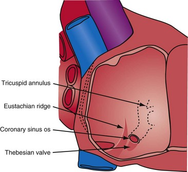
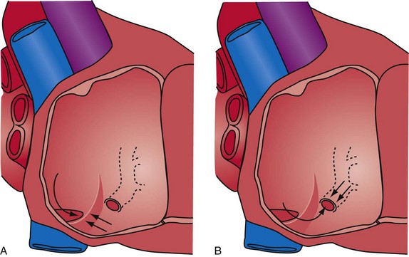
Successfully locating the CS os is facilitated by a complete understanding of the anatomy. Figure 22-40 shows the structures that affect locating the os. A catheter approaching the CS os along the posterior wall of the right atrium (RA) clearly will be deflected away from the os by the eustachian ridge (Fig. 22-41, A). When approaching the CS from below (Fig. 22-41, B), catheter entrance is blocked by the thebesian valve. The key to easy, rapid location of the CS os is for the catheter tip to approach the os from the posterior superior tricuspid annulus (Fig. 22-42, B), thus using the eustachian ridge and thebesian valve to direct the catheter toward (not away from) the os, as seen with the femoral approach, in which the catheter reaches over the eustachian ridge, approaching the os from above (Fig. 22-42, A). Using counterclockwise torque and the correct technique, a properly shaped catheter can be directed into the CS os from the posterosuperior tricuspid annulus inferiorly toward the RA, thus using the eustachian ridge and thebesian valve to guide the tip of the catheter toward the os. Figure 22-43 demonstrates the effect of counterclockwise torque. The tip is directed posteriorly where it contacts the heart. With additional torque, the tip moves inferiorly and toward the RA. To approach the CS from above, the catheter tip must be superior to and on the RV side of the os. If the guide starts at or below the CS os, counterclockwise torque directs the tip posteriorly and inferiorly away from the os into the RA (Fig. 22-44).
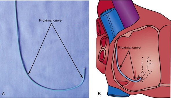
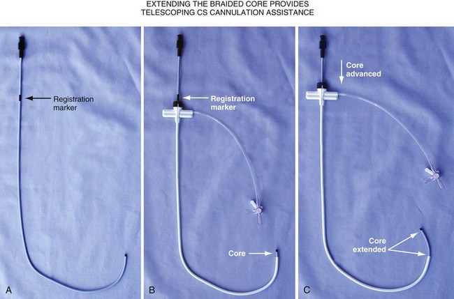
Changing the shape of traditional catheter by adding a “proximal curve” places the tip above the CS on the tricuspid annulus or in the right ventricle so that torque will direct the tip into the CS (Fig 22-45; see also Fig. 22-48, A). Currently all the device companies provide a braided catheter with an anatomic shape with the proximal curve (Fig. 22-46). To provide the torque control required for CS cannulation and still retain a peel-away sheath, the Pressure Products CSG-Worley Braided Core Series uses a temporary metal braid, the braided core (Fig. 22-47, A). The extra length of the braided core also serves as a telescoping cannulation assist catheter (see Fig. 22-18). By extending the braided core, the implanter can change trajectory and shape of the CS access catheter (Figs. 22-47, B and C, and 22-48, B). St. Jude Medical offers cannulation assist catheters in their new delivery system (CPS AIM SL, CSL/SL AL2).
Locating CS Os with Contrast Injection System
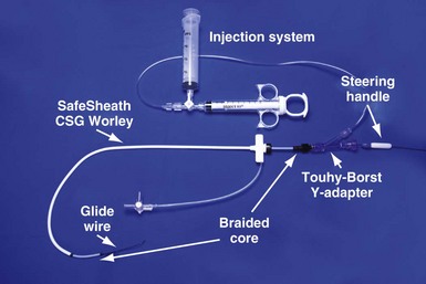
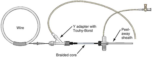
Pressure Products CS cannulation includes the injection system attached to the braided core, which is telescoped into the SafeSheath CSG Worley (Fig. 22-49). The injection syringe is attached to a three-way stopcock. The reservoir syringe is also connected to the stopcock. A short piece (8-12 inches) of extension tubing is connected from the stopcock to a Y-shaped adapter with a Touhy-Borst valve. The extension tubing allows the operator to manipulate the guide while the assistant injects contrast material. The reservoir syringe is filled from a small bowl of contrast agent (not shown). One can fill the injection syringe several times from the reservoir syringe by rotating the stopcock open to the reservoir syringe. A Terumo Glidewire can be inserted through the Touhy-Borst valve on the Y-adapter if needed. Note that the entire system is contained on the table to help preserve sterility.
 Coronary Sinus Cannulation: Two-Step Process with Contrast Injection
Step 1: Locating Coronary Sinus Os
The variable location of the CS os in patients with congestive heart failure explains why it can be difficult to find even with contrast injection. The location of the os varies because of cardiac rotation, cardiac dilatation, and distortion from previous open-heart surgery. When viewed on the fluoroscopy screen in the AP view, the CS os can be to the right or left of the spine (Fig. 22-50). Note that in both cases shown, the os of the CS is at the proximal end of the distal coil. In addition, the os may be high or low relative to the floor of the tricuspid annulus (Fig. 22-51). Systematic use of contrast injection with an understanding of the anatomy allows the operator to recognize quickly where the catheter tip is in relation to the CS os (Fig. 22-52). The direction of the catheter can then be adjusted.
Anatomy Surrounding CS Os as Defined by Contrast Injection
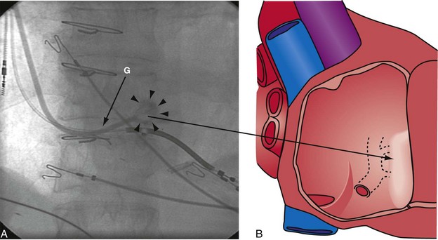
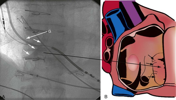
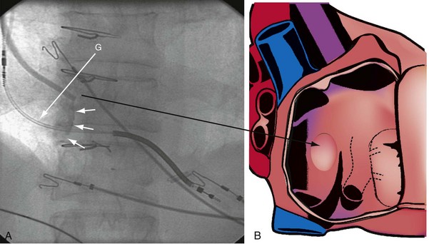
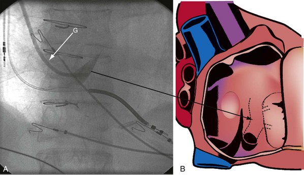
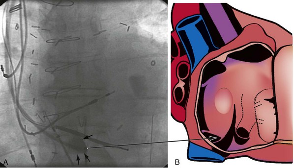
The right ventricle (RV), tricuspid annulus, eustachian ridge (valve of IVC), thebesian valve (valve of CS), os of the CS, and subeustachian space are all important structures in the search for the coronary sinus os. These landmarks are readily identified with full-strength contrast injection. In Figure 22-53, A, the tip of the CS access catheter is across the tricuspid annulus and directed posteriorly with 20 to 30 degrees of counterclockwise torque. A 2-mL puff of contrast agent outlines the trabeculae and confirms the location of the CS access catheter in the RV. In Figure 22-53, B, additional counterclockwise torque directs the tip inferiorly and toward the right atrium (RA). Trabeculae confirm that the CS access catheter is still in the RV. In Figure 22-54, contrast agent is trapped between the tricuspid valve and posterior wall of the RV, outlining the tricuspid annulus. In Figure 22-55 the tip of the CS access catheter is in the RA near the fossa ovalis. In Figure 22-56 the tip of the CS access catheter enters the CS os. The subeustachian space is another important landmark defined by contrast injection (Figs. 22-57 and 22-58).
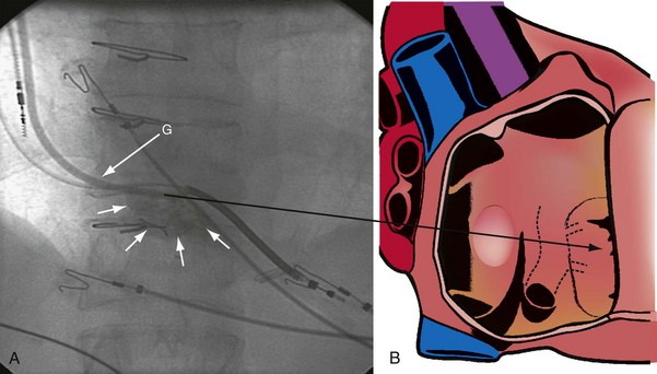
Figure 22-53 Composite illustration with guide in right ventricle.
A, Anteroposterior projection with the guide (G) rotated 20 to 30 degrees further counterclockwise than in Figure 22-52. The additional counterclockwise torque directs the tip down toward the coronary sinus os. A 2-mL puff of contrast material outlines the trabeculae (short arrows), confirming that the tip of the guide is in the right ventricle. The guide is inferior to the position of the guide in Figure 22-52. B, Drawing of the heart corresponding to A, showing location of the guide tip (long arrow).
It must be recognized that when the tip of the CS access catheter is in the subeustachian space, it is below and on the atrial side of the CS os. Counterclockwise torque will direct the tip from the subeustachian inferiorly and toward the RA away from the CS os. Before starting to search for the CS, the tip of the CS access catheter must be advanced across the tricuspid valve into the RV. This can be accomplished by withdrawing the CS access catheter 1 cm, applying 20 degrees of clockwise torque to orient the tip toward the tricuspid valve, and then advancing the CS access catheter into the RV. If the tip of the CS access catheter remains in the RA, a wire may be advanced through the Touhy-Borst valve and through the tip of the CS access catheter into the RV (Fig. 22-59). Once the wire is in the RV, the CS access catheter is advanced over the wire into the RV (Fig. 22-60).
Procedural Steps
Quickly finding the CS os involves the following steps:
Coronary Venous Anatomy
Compared with the coronary arterial system, the coronary venous system receives little attention. With CRT for heart failure, the coronary venous system is used to access target areas and implant the LV pacing lead.47,48 In the early days of CRT, implanters were forced to use a “take what’s available” approach to LV lead implantation. With experience and new implantation tools, physicians are increasingly inclined to place the lead in a specific location. As a result, the implanting physician will need to study the patient’s coronary venous circulation to determine the best way to direct the LV lead to the desired location. Under these circumstances, a complete set of well-performed cine-venograms is important.
Half-Strength versus Full-Strength Contrast
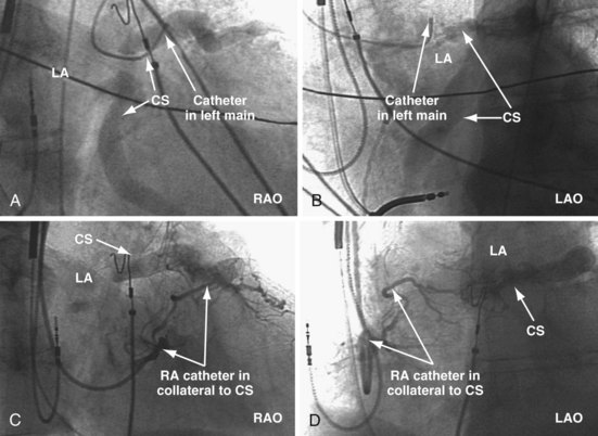
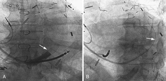
Limited visualization is obtained with occlusive CS venography using half-strength contrast agent (Fig. 22-61). Full-strength contrast provides much better visualization of the venous system, both antegrade filling and retrograde filling (Fig. 22-62). Full-strength contrast agent also visualizes venous collateral vessels that may be used for retrograde placement of the LV lead if the antegrade approach is problematic (Fig. 22-63). Venous anomalies that may be important to lead placement also are better visualized (Fig. 22-64).
Occlusive Coronary Sinus Venography
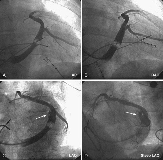
The occlusive CS venogram is the best way to establish the coronary venous anatomy for LV lead placement. Full-strength contrast should be used; otherwise, vessels are not well seen, retrograde filling of proximal veins is difficult to appreciate, and a potential approach to the target area may be missed. Because of incomplete visualization, the total contrast load may be ultimately greater with half-strength injections. If the balloon does not occlude the mid-CS, it can be advanced further into a narrow portion of the CS and inflated. The vessels proximal to the occlusion can usually be seen as they fill retrograde. Alternatively, the balloon may be double-inflated. When imaging the coronary venous system, it is tempting to “jump ahead” after the first injection; for efficient, effective lead placement in every case, however, it is essential to obtain all three views to fully visualize the anatomy. In many cases, the critical anatomic information required is apparent in only one view. Without all views the implanter may work for hours on the basis of a false assumption about the venous anatomy. For example, as illustrated in Figure 22-65, both the AP (not shown) and LAO venogram views make it appear that the patient’s venous anatomy is straightforward, with no further contrast agent required. After more than one hour of unsuccessful lead manipulation, the RAO CS venogram showed the proximal takeoff and parallel course of the target vein. With the venous anatomy understood, the lead was quickly placed. The time wasted because of the lack of knowledge about the venous anatomy in one case easily justifies multiple additional occlusive venogram projections. Figures 22-66 to 22-70 provide examples of the importance of multiple views.
Measures to Overcome Failure to Visualize Anatomy
Selective Injection of Anterior or Middle Cardiac Vein
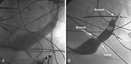
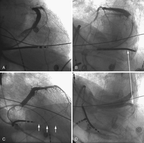
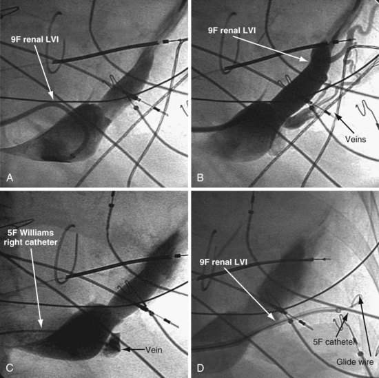
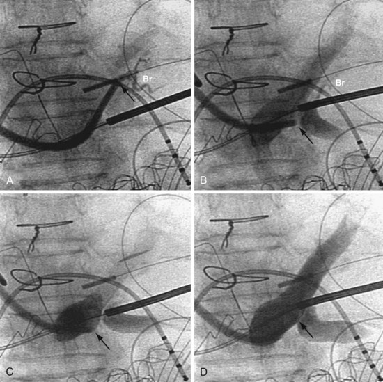
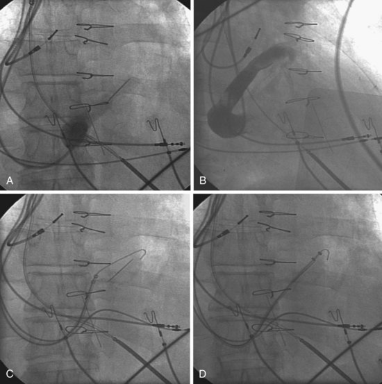
In some cases, despite adequate occlusive CS venograms, no lateral veins are identified but the anterior and middle cardiac vein are seen. Injection of the anterior or middle cardiac with the vein selector usually fills a lateral wall vein via collaterals. If more contrast is needed, the delivery guide is used (Fig. 22-71). In some cases, contrast injection through a delivery guide into the body of the vein may not be helpful (Fig. 22-72); in this case, the vein selector (Impress CS Standard) can be advanced into a small-branch vein. Contrast injection into the small branch will usually reveal a target vein to the lateral wall through collateral filling (Fig. 22-72, C), with subsequent lead placement (Fig. 22-73).
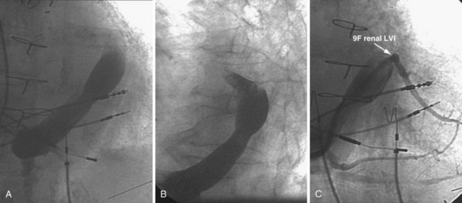
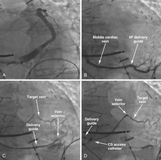
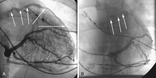
Figure 22-72 Subselective injection of middle cardiac vein is required to identify and cannulate a lateral vein.
A, Multiple occlusive venograms failed to reveal a lateral vein but did demonstrate the middle cardiac vein. B, Injection of contrast through a 9F delivery guide in the middle cardiac vein does not reveal a lateral vein. C, The 5F vein selector is in a superior branch of the middle cardiac vein that drains the lateral wall of the left ventricle. Contrast injection fills the lateral vein, which is seen to drain into the coronary sinus. D, Lateral vein is engaged with tip of the 5F vein selector, and contrast is injected. Venoplasty was required for LV lead placement (see Fig. 22-73).
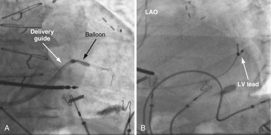
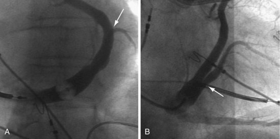
Figure 22-73 Vein requiring venoplasty for lead to advance.
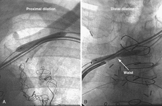
A, The 9F delivery guide is at the ostium of the lateral vein shown in Figure 22-72. The balloon is inflated just inside the ostium. As the balloon is deflated, the delivery guide is advanced into the vein. B, Left anterior oblique (LAO) projection of the left ventricular (LV) lead is in place in the lateral vein after venoplasty,
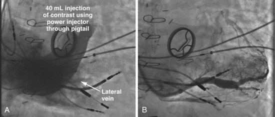
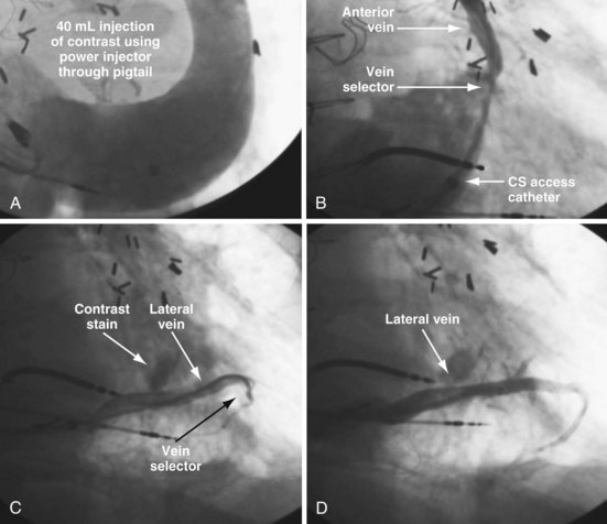
In patients with a persistent left SVC where an occlusive venogram is not possible, our initial approach was to place a 5F pigtail catheter in the mid CS and use a power injector (Fig. 22-74). However, this is not always successful (Fig. 22-75). The soft, tapered-tip vein selector (Impress CS Standard) can be advanced into the CS, turned laterally, and manipulated carefully along the lateral wall in the LAO projection. When the tip is seen or felt to engage a structure, careful contrast injection will locate a coronary vein. Figure 22-75 shows a patient with a persistent left SVC where three 40-mL power injections of contrast failed to reveal veins to the lateral wall. Vein dissection is possible with forceful injections, but the tip of the Impress CS vein selector is softer than most catheters available from the cardiac catheterization laboratory and thus less likely to dissect.
Coronary Artery Injection with Venous-Phase Images
If no veins draining the lateral LV wall can be visualized with the first three approaches, injection of the coronary artery with delayed images for venous return can be effective49 (Figs. 22-76 and 22-77).
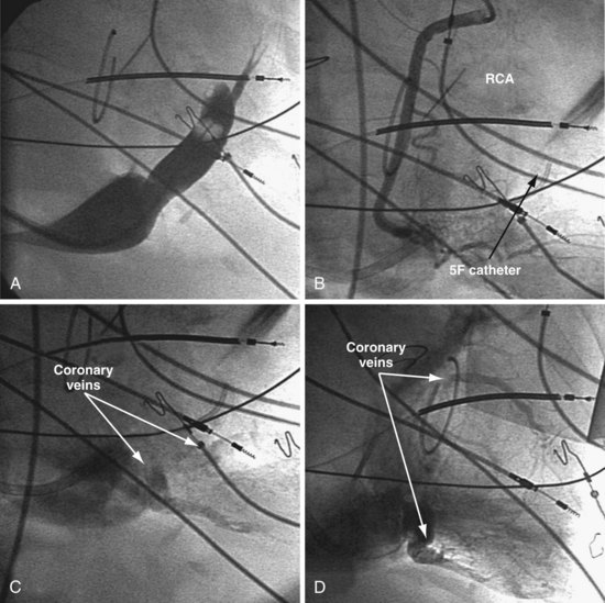
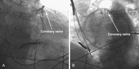
Figure 22-76 Coronary veins identified only on delayed images after contrast injection into coronary artery.
A, The coronary sinus (CS) is identified. Despite multiple attempts, including double-balloon inflation and injection of full-strength contrast material, the veins draining the lateral wall are not visualized. B, Attempts are made selectively to cannulate and inject veins to the lateral wall with a 5F catheter. After the veins have not been identified by occlusive venography or selective retrograde injection, arterial access is obtained, and selective injection of the right coronary artery (RCA) is performed. The RCA is shown with imaging during the initial contrast injection. C, Left anterior oblique projection of delayed imaging after RCA injection shows the coronary veins draining into the CS. D, Right anterior oblique projection of delayed imaging after RCA injection reveals the coronary veins draining into the CS. Currently, coronary injection can usually be avoided by the use of the soft tip vein selectors as described for patients with a persistent left superior vena cava (see Figure 22-75).
Cannulation of the Difficult Coronary Sinus
As discussed previously, it is much easier to cannulate the CS with a telescoping, anatomically shaped CS access catheter and contrast than with other approaches. Contrast with the appropriate tools eliminates the need for the more complex approaches described by Bashir et al.50
Finding the Difficult CS Os
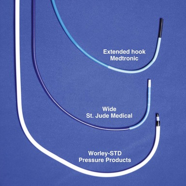
Catheter Shape Not Suited to Anatomy
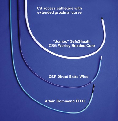
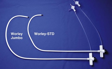
The most common cause of difficulty finding the CS os is when the shape of the CS access catheter does not place the tip across the tricuspid valve and above the CS os when counterclockwise torque is first applied. This situation is common with nonanatomic-shaped CS access catheters. It can also occur with a massive right atrium where the proximal curve of an anatomic-shaped catheter is too short to carry the tip across the RA to the tricuspid annulus (Biotronik ACS Extended Hook, Boston Scientific Acuity CS Extended Hook, Medtronic Attain Command Extended Hook, Pressure Products CSG-Worley STD, St. Jude Medical CPS Direct Wide). Catheters designed to solve this problem by extending the proximal curve include the Boston Scientific Acuity CS-W, Medtronic Attain Command Extended Hook XL, Pressure Products CSG-Worley Jumbo with braided core, and St. Jude Medical CPS Direct Extra Wide (Fig. 22-80). In addition, the reach of the catheter can be extended with a telescoping cannulation assist catheter, such as the included braided core of the Pressure Products Jumbo or the addition of the optional St. Jude CPS AIM SL. Diagnostic catheters such as an AL2 can also be tried.
Anatomic Variants
High Coronary Sinus Os
If the CS is high (superior), as in Figure 22-81, the tip of the catheter must start above or else counterclockwise torque will direct the tip of the catheter posteriorly and inferiorly, away from the CS os.
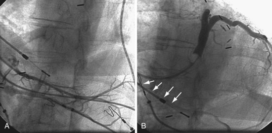
Figure 22-81 High coronary sinus (CS) os is difficult to locate.
A, The only vein found on the initial attempt by a previous operator is low. B, The high CS os is easily cannulated with use of the approach described in Figure 22-60. Retrograde filling of the previously injected vein can be seen (arrows).
Tricuspid Valve Ring
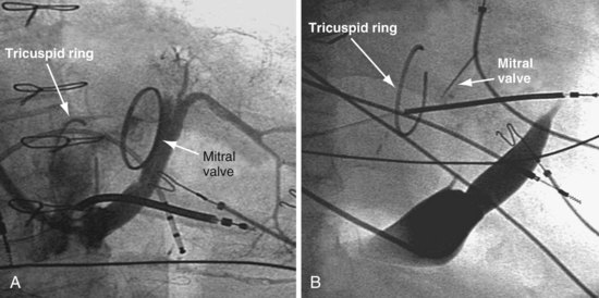
The tricuspid repair/ring placed in patients with severe congestive heart failure and tricuspid regurgitation may distort the anatomy. As illustrated in Figure 22-82, the CS os is easily found in one case (A) and difficult to find in another case (B).
Giant Right Atrium
When the RA is greatly dilated, as in permanent atrial fibrillation and tricuspid regurgitation, the tip of even a properly shaped guide/sheath may end up in the RA below the tricuspid valve where torque will direct the tip away from the CS. A sheath/guide with an extended proximal curve specifically designed for the massive RA may be selected (Fig. 22-83).
Coronary Sinus Empties into Left Atrium
In rare cases, the CS empties into the left atrium (Fig. 22-84). Injection of contrast material into a coronary artery with imaging of the venous phase demonstrates the location of the CS os. In addition, a small vein leading to the CS is cannulated. The only way to reach the CS is via the transseptal approach.
Step 2: Advancing a Sheath or Guide into the Coronary Sinus
Sheath/Guide Difficult to Advance
Anchor Balloon Technique
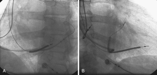
In some cases, a .014-inch angioplasty wire is all that will advance, and attempts to advance a catheter result in wire displacement. In this situation the venogram balloon or a coronary balloon can be inflated in the CS or a branch vein and used as an anchor (see Fig. 22-88 and Chapter 23).
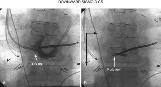
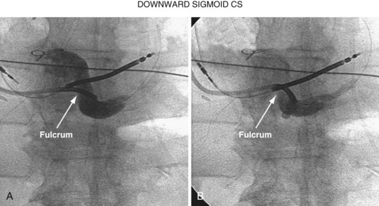
When there is a downward sigmoid CS valve near the os, the telescoping approach can be used to redirect the angle of approach. If the sheath is placed on the lip of the CS and held in position, and the braided core is advanced out the sheath, the sheath will help support the guide and resist the downward trajectory, allowing the braided core to advance into the CS rather than dropping down into the right atrium. Figure 22-93 illustrates this concept diagrammatically, and Figure 22-94 provides a patient example.
Selecting Target Vein
Selection of the target vein determines the shape of vein selector and the size of delivery guide.
Recent speculation (wishful thinking) suggests that one LV pacing site is as good as the next for CRT, in which case the target vein becomes the easiest vein in which to place the lead. Our experience with CRT nonresponders does not support this position. We have seen too many CRT nonresponders improve dramatically when the pacing site is moved from an anterior or apical position to the lateral free wall (see Figs. 22-5 to 22-7 and 22-9 to 22-11). For now, we make every effort to place the LV lead on the midlateral LV free wall by whatever means possible.
Placing Lead in Target Vein
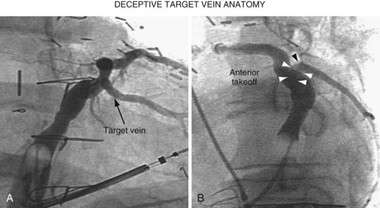
Once insertion of the CS access catheter has established a stable platform with adequate lumen size, it is time to place the LV lead. Multiple factors determine how difficult it is to place a lead in a specific vein, including the angle a vein forms as it empties into the CS (Fig. 22-95), its tortuosity (Fig. 22-96), small size (Fig. 22-97), and presence or absence of stenosis (Fig. 22-98). In many cases the takeoff looks easy but is deceptive and difficult (Fig. 22-99). The size, method of delivery, method of fixation, and lubricity of the LV lead not only affect lead placement but also whether a vein is suitable for LV pacing; the physical characteristics affect stability, pacing thresholds, and phrenic pacing. Replacement with a lead that is larger or that has a different shape or method of fixation can resolve stability and pacing issues in the target vein.
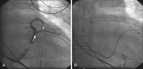
Figure 22-95 Placement of left ventricular (LV) pacing lead on lateral wall through ideal venous anatomy.
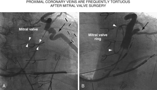
Figure 22-96 Two patients with highly tortuous, proximal coronary veins after mitral valve replacement or repair.
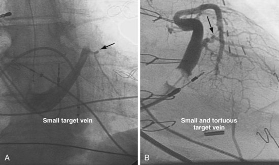
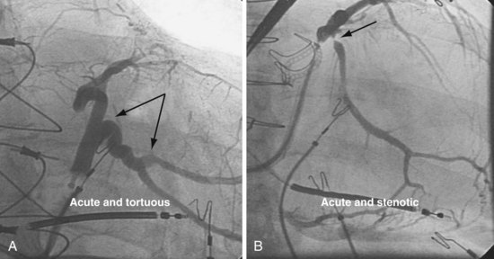
Figure 22-98 Target veins with acute tortuous and acute stenotic takeoff.
A, Takeoff from the coronary sinus is acute and tortuous. B, Takeoff from CS is acute and stenotic.
Matching Left Ventricular Lead to Venous Anatomy
Method of Fixation
Fixation can be either active or passive. Approaches to passive fixation include tines (straight), single curve, double curve (S shape),51,52 and double cant. In the right atrium and right ventricle, tines catch in the trabeculae, but in a venous branch of the CS, tines are intended to wedge in the vein as it is advanced distally. Nof et al.53 found no significant differences in success or complication rates among passive-fixation leads. However, high pacing thresholds, phrenic pacing, and an unstable lead position can be resolved by changing to an alternative form of passive fixation;54 that is, change the lead. If lead selection is limited to one company’s products, a less desirable target vein or even implantation failure may result.
Left ventricular leads can be actively fixed via screw (Select Secure, Medtronic)55 or deployed lobes (Attain 4195 StarFix, Medtronic).56,57 Although fewer dislocations occur and thresholds are more stable with deployed lobes than passive fixation, fibrotic tissue growth into the extendable lobes will seriously complicate extraction.57–60 Although limited data support screw fixation, the leads are expected to remain extractable.55 With the current selection of leads with different forms of passive fixation, a patient in whom implantation previously failed or resulted in a compromised lead position can undergo successful lead implantation through selection of the appropriate lead for the vein, without the need for active fixation.54
Over-the-Wire or Stylet-Driven Design
The only company that continues to offer leads that are only stylet driven is ELA.
Selecting Shape of Vein Selector
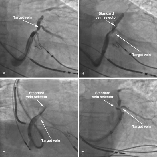
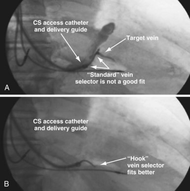
As mentioned, the current approach relies on the shape of the vein selector, not the delivery guide, for target vein cannulation, which is now possible because of the soft tip on selectors and guides. One of the three shapes of vein selector (see Fig. 22-3) will be suitable to locate, cannulate, and wire “all” target veins encountered. The CS Standard is suitable for the majority of veins, although the CS Hook and CS Vert are occasionally needed. In some cases it is clear from the venogram that the CS Standard is not ideal (Fig. 22-100), but in other cases it is a matter of trial and error (Fig. 22-101). The CS Hook can be useful near the CS os and with other veins that have an acute takeoff. The CS Vert is helpful when the takeoff is less acute but tortuous. The black distal section of the catheter is soft and can be easily straightened as it is advanced over wires into the target vein. Thus, once the ostium of the vein is identified by a puff of contrast, the wire can be advanced, followed by the vein selector to add a second wire. The vein selector is advanced deep into the vein over the wires and allows creation of a stable rail over which to advance the delivery guide.
Selecting Lumen Size of Delivery Guide
The size of the lead suitable for the target vein determines the lumen size of the delivery guide to be used. For 6F to 7F leads, use the 9F OD/7F ID renal shape delivery guide (SafeSheath, Worley Telescopic Renal Shape Lateral Vein Introducer: LVI/75-5-62-07-RE) (see Fig. 22-21, B). For the 4F to 5F leads, use the 7F OD/5F ID renal-shaped delivery guide (LVI/75-5-66-5.5-RE) (see Fig. 22-21, A) or the device company delivery guides. The soft-tip section of the delivery guide can be advanced deep into a target vein over the vein selector if needed. As a result, we now rely on the shape of the vein selector, not the shape of the delivery guide, to accommodate the takeoff of various veins.
Selecting Shape of Delivery Guide
In the previous edition of this book, there was emphasis on matching the shape of the delivery guide to the anatomy because of the stiff-tip section of the guides in use at the time (guides obtained from radiology and first-model LVI). The soft tip of the current Pressure Products delivery guide used with the new soft-tip vein selector allows for one shape (the Renal, with the longest soft-tip section) to accommodate almost all venous anatomy (Fig. 22-102).
Deploying Vein Selector and Guide Through Access Catheter
Figure 22-103 demonstrates how to use the combination of the vein selector and delivery guide with the CS access catheter. When looking for the target vein with the vein selector, proper interventional technique must be used. Do not attempt to manipulate the catheter with one hand and inject contrast with the other (Fig. 22-104).
Locate, “Wire,” and Create Rail in Target Vein for Guide
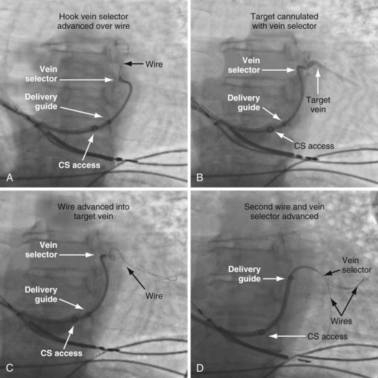
To locate the target, the vein selector ID is rotated laterally and directed along the CS to where the vein was seen on the occlusive venogram. When the tip of the catheter falls outside the body of the CS or the tip fails to advance with gentle pressure, this suggests the vein selector is in the target. Ideally, puffs of contrast are only used to verify position, but may be necessary to reveal the target vein location. With the vein selector in or near the target vein, a .014-inch floppy wire is advanced, followed by the vein selector, then another wire (Figs. 22-105 and 22-106).
Techniques for Cannulation of Target Veins Close to CS os
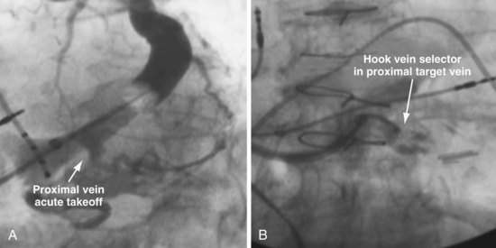
Delivering a lead to a target vein where the takeoff is just inside the CS os can be difficult because CS access is lost as the catheters are withdrawn in an attempt to engage the vein. Figure 22-107 illustrates a method that we have found helpful.
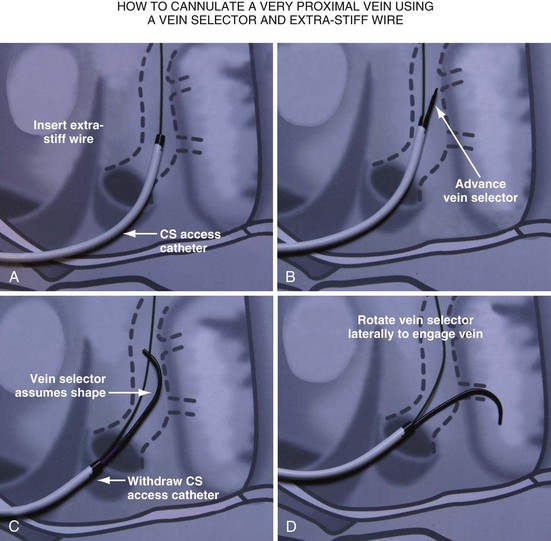
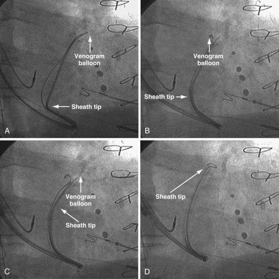
Figure 22-107 Cannulation of proximal target vein using guidewire to maintain CS access and vein selector to cannulate vein.
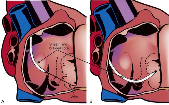
A, With 9F ID coronary sinus (CS) access catheter in place, a .035-inch extra-stiff J-tip guidewire is advanced deep into the CS. B, The 5F vein selector (Impress CS Standard) is advanced into the CS. The CS access catheter prevents the vein selector from taking shape. C, CS access catheter is withdrawn out of CS os, and the vein selector takes shape. CS access catheter is maintained in position by the extra-stiff wire. D, Vein selector is rotated laterally, and puffs of contrast are used to locate the target vein. The ability to control the catheter with both hands and inject contrast without diverting attention from the location of the catheter tip is important for success; thus, contrast must be injected as shown in Figure 22-104, B, not A. If the vein selector falls out of the CS while attempting to engage the target vein, it is withdrawn into the CS access catheter, which is advanced back into the CS and the process repeated.
Removing Vein Selector (Retain Wires and Deliver Lead)
It is particularly important that the instrument table be perpendicular to the patient table as the vein selector is withdrawn. To prevent the delivery guide from being displaced during the process of removal, it is important not to advance the wires as the vein selector is removed. To maintain wire access in the vein, it is important not to pull the wires out as the vein selector is removed. Keeping the wires in a stable position during the process is best accomplished with the catheters in a straight line resting on the table. Once the lead is in place, it is time to discuss removing the delivery system without displacing the leads. Figures 22-108 to 22-112 provide step-by-step illustrations of how to use the vein selector with the delivery guide.
Removing CS Access Catheter
Final Stylet Position
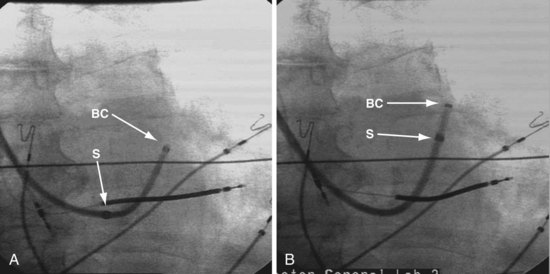
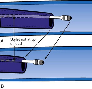
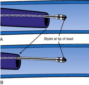
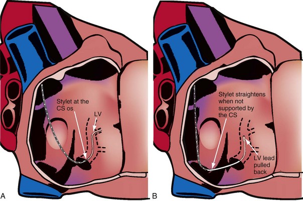
Delivery guides also allow the stylet to be advanced to the tip of the lead without displacing the lead. When over-the-wire pacing leads are used, it is critical to remove the angioplasty wire and replace it with a soft stylet or fixing wire to stabilize the lead before delivery guide and CS access catheter removal. If either is removed with the angioplasty wire in place, friction between the guide/sheath and the pacing lead slides the lead back over the wire (Fig. 22-113). Figure 22-114 illustrates one of the advantages of using a delivery guide for the LV lead. The telescoping delivery guide supports the lead in the target vein while the angioplasty wire is removed and the stylet advanced. Before the stabilizing stylet is inserted, the distal 8 to 10 cm of the stylet should be gently curved (Fig. 22-115). The importance of using a soft, curved stylet becomes apparent once guides and sheaths are removed. The stylet should always be advanced to the tip of the pacing lead. When the stylet is not at the tip of the lead, friction between the CS access catheter and the pacing lead will slide the lead back over the stylet (Fig. 22-116). If the stylet is at the tip, the lead position will remain constant as long as the position of the stylet is fixed (Fig. 22-117). The stylet should never be left at the mid-CS level, but should be advanced all the way to the tip of the lead. The telescoping delivery guide supports the lead so that the stylet can be advanced to the tip of the lead without fear of displacing the lead out of the target vein (Fig. 22-118). Once the soft, curved stabilizing stylet is in place, the delivery guide and CS access catheter can be removed.
Nonanatomic Catheter Shape
Catheter Rebound
When the catheter is forced into the CS, its shape is maintained by pressure against the CS. When the tip clears the CS os, the catheter resumes its intrinsic shape, falling into the right atrium and potentially displacing the lead (Fig. 22-119). If the CS access catheter is anatomically shaped, it does not require CS support to maintain its shape thus when it clears the CS, it does not fall into the right atrium. Figure 22-120 illustrates withdrawal of an anatomically shaped sheath from the CS.
Lead Length
With the CS access catheter in place, the length of lead in the body is determined by the length of the catheter between CS and the body surface. There is more catheter (thus more lead) in the heart with the long, sweeping curve of an anatomic catheter than a straighter catheter that takes a direct course to the CS as it is bent to fit into the CS. Once the nonanatomic CS access catheter is removed, additional lead length is required (Fig. 22-121). When the cutting hand is fixed as the CS access catheter is removed, no additional lead is advanced into the body. The lead length will be inadequate and may be displaced between the time the CS access catheter is removed and the time the operator can advance an additional lead.
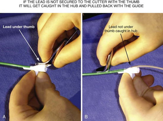
Hub Design
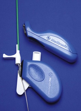
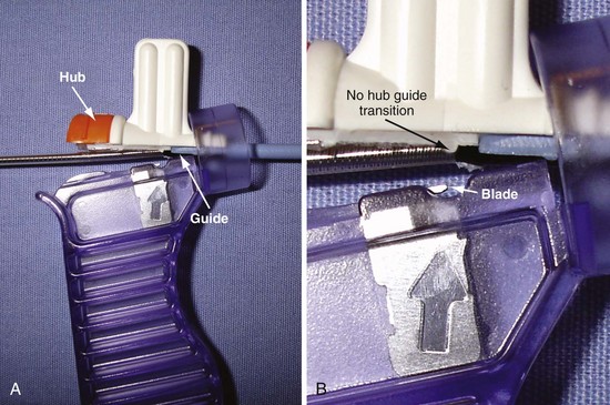
Cutting a braided CS access catheter and/or delivery guide requires a hemostatic hub designed to be either sliced (Figs. 22-122 and 22-123) or removed (Fig. 22-124) after the lead is placed. The Biotronik and Medtronic systems use a removable hemostatic valve and a sliceable hub (see Fig. 22-124). The sliceable plastic hub is joined to the braided catheter by overlapping the plastic and braid. The resistance to cutting increases significantly as the blade reaches the plastic hub to guide overlap, then decreases abruptly as the blade reaches the guide. The sudden change in resistance can cause the cutting hand to jump at the same time as the tip of the guide is prone to disengage from the CS. Acting synergistically, these factors tend to displace the lead. The Boston Scientific and ELA braided CS access catheters use the Pressure Products type of breakaway hub, which exposes one-half the circumference of the proximal end of the guide (Fig. 22-125; see also Fig. 22-122). There is no guide-hub overlap, so resistance to slicing is uniform. The Boston Scientific integrated hemostatic valve is similar to the Pressure Products breakaway hub, but hub-guide overlap changes resistance to cutting (see Fig. 22-143). The sliceable hub of the St. Jude braided CS access catheters and delivery guide is a new, asymmetrical design in which the guide extends the full length of the hub, forming part of the outer wall (see Figs. 22-122 and 22-151). Thus, Boston Scientific, ELA, Pressure Products, and St. Jude designs have integrated, slittable hemostatic hubs, which avoids the troublesome hub to guide transition.
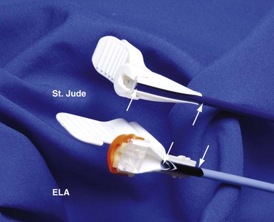
Figure 22-122 Comparison of integrated sliceable hemostatic hub technology for removal of braided CS access catheter.
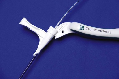
Figure 22-123 Integrated sliceable hemostatic hub technology.
For removal of a braided coronary sinus (CS) access catheter (St. Jude Medical).
Splitting Hub/Guide without Grabbing and Displacing Lead
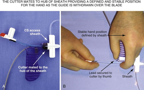
After it is cut, the thick plastic of the hub of the guide can close around the lead. Unless carefully removed from the grip of the cut hub, the lead will be jerked abruptly when the hub reaches the IS-1 connector (Fig. 22-126). A technique to avoid the issues with slicing that occur as the catheter clears the CS is to withdraw the braided guide over the lead as far as the lead length will permit, often moving the tip above the right atrium before cutting. However, cutting a braided catheter that has been withdrawn to the IS-1 connector can be problematic. There is no way to stabilize the lead and no place to support the cutting hand. The slicer for the Pressure Products delivery guide is designed to mate to the hub of the CS access catheter, providing a defined, stable position to support the cutting hand (Fig. 22-127).
Long Peel-away Catheter Removal
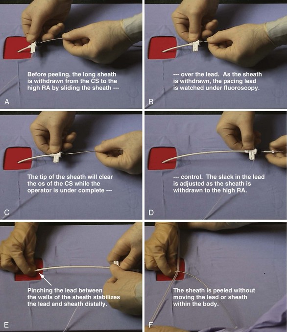
Anatomically shaped, peel-away CS access catheters are less prone to dislodge the lead as they are removed. Before cracking or peeling occurs, the operator withdraws the catheter, watching the tip under fluoroscopy until the hub reaches the IS-1 connector. This permits easier adjustment of the lead length in the right atrium as the tip clears the CS os. Separating the step of removing the sheath/guide from the CS from the step of peeling permits advancement of the lead if its location is demonstrably unstable. Figure 22-128 shows that lead stability and hemostasis are facilitated if the operator does not remove the hemostatic valve and withdraws the sheath over the pacing lead to the IS-1 connector. As the sheath is withdrawn, both the portion in the atrium and the tip of the LV lead should be in the fluoroscopic field so that the operator can judge the length of lead required as the supporting sheath is removed. This approach minimizes blood loss and the risk of air embolization, because the hemostatic valve is not removed until it is withdrawn to the IS-1 connector. Because there is no braid, the walls of the sheath can be pinching against the lead, reducing blood loss and risk of air embolization once the valve is removed. It is much more difficult, if not impossible, to pinch a catheter effectively with wire braid incorporated in the wall.
Stylet Removal
Stylet Characteristics
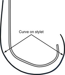
When the stylet is in the lead within the CS, the shape of the lead/stylet combination is determined by the course of the CS. Once outside the CS, the stylet is no longer supported. When the shape of the stylet and course of the LV pacing lead do not match, the stylet determines the ultimate shape of the lead/stylet combination, often by withdrawing the tip from the target vein. The stiffer the stylet, the greater is the displacing force applied to the lead. Placing a gentle curve on the stylet that approximates the final course of the lead through the right atrium reduces the tendency for the stylet to displace the lead because of a shape mismatch. A softer stylet exerts less displacing force when the shape of the stylet and course of the lead do not match despite the curve. I advise use of a soft, gently curved stylet advanced to the tip of the lead (see Fig. 22-115). Figure 22-129 illustrates what can happen if a stiff straight stylet is used.
Method of Stylet Withdrawal
As discussed, when the shape of the stylet and course of the LV pacing lead do not match, the stiffer stylet will prevail, often by displacing the lead. The longer the stylet remains in a position prone to displacing the lead, the more likely the lead will be displaced. To prevent the stylet from displacing the pacing lead when the course of the lead and the shape of the stylet do not match, the stylet is removed quickly (like pulling the cord on a lawn mower). This maneuver gives the stylet less time to displace the lead. Before insertion into the LV pacing lead, the stylet should be curved, as shown in Figure 22-115.
Final Slack on Lead
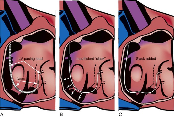
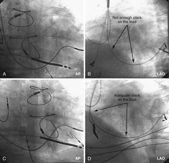
The final step in LV lead placement is to be certain that the lead has adequate slack. Appearance on AP and RAO projections can be deceptive about this issue. The LAO projection is best for judging the amount of slack in the lead. In the LAO projection, the RV and LV leads should appear to touch low in the right atrium (RA) and continue parallel in close proximity as they leave the RA into the SVC. Figure 22-130 is an example of dislodgment of the lead caused by insufficient slack; note the trajectory in the LAO projection with insufficient slack in B compared with adequate slack in D. To ensure adequate slack on the LV pacing lead, the operator should inspect the steep LAO projection to confirm that the LV and RV leads appear to touch in the low RA.
[/level-membership-for-cardiovascular-category][not-level-membership-for-cardiovascular-category]
22 Left Ventricular Lead Implantation
Cardiac resynchronization therapy (CRT) reduces the chance of hospitalization, improves quality of life, and lowers mortality from congestive heart failure.1–4 CRT requires left ventricular (LV) pacing, usually by a lead placed transvenously through a coronary vein on the epicardium.5–7 Transvenous pacing of the LV epicardium through the coronary venous system can be technically difficult,2,8 but it is safe, and thresholds remain stable.7,9
Transvenous LV lead implantation was new in 1998 and, as with most new therapeutic procedures, required the development of tools and techniques for its safe and cost-effective implementation into clinical practice.10 Because CRT devices were implanted predominantly by electrophysiologist (EP) physicians, their skill set and experience determined the initial tool set. Unfortunately, the EP-suited tools did not overlap well with those useful for LV lead implantation, resulting in a steep learning curve, long case times, and failed implants. Using the EP skill set, pioneering physicians and early adopters eventually developed their own technique, employing a combination of the limited tools designed for the procedure and existing tools that proved useful through improvisation;11–20 however, some patients experienced adverse results.21–25
Overview
Several notable developments have occurred since the last edition of this textbook. Electronic repositioning in conjunction with bipolar leads (soon to be multipolar leads) has greatly improved success.26 The most important development involves delivery systems.27,28 Telescoping guide support–based delivery systems employ sliceable, preshaped guides for insertion through a separate coronary sinus (CS) access catheter that delivers leads directly to the target vein, allowing for interventional techniques.29,30 Optimal use requires the physician to learn and apply such principles as safe use of contrast, manipulation of open-lumen catheters, effective and efficient injection of contrast, and importance of table position.31
Although an important advance, the new guide support–based delivery systems have two limitations: (1) most do not offer a delivery guide for leads with diameter of 6 to 7 French, and thus only leads 5 Fr (5F) or less usually are deliverable, and (2) most lack a vein selector. A vein selector serves two functions. First, it locates and cannulates the target vein. The design parameters required for a delivery guide, however, limit the ability to locate and cannulate the target vein. It is easier and safer to use a small catheter with a flexible tip to locate the target vein than a catheter designed to provide support for lead delivery. Second, the vein selector provides a rail for the delivery guide. Once the delivery guide locates the vein, it may not be possible to advance into the vein. If a small, flexible-tip catheter is telescoped into the vein through the delivery guide, it can be used as a rail to ensure the tip of the guide engages the vein. The small catheter with a flexible, tapered tip that telescopes through the delivery guide to locate the vein, then act as a rail over which to advance the guide, is a “vein selector” (Fig. 22-1).
Although catheters from interventional radiology and cardiology can be used as vein selectors, they are the wrong length, the tips are too stiff, and the shapes are not ideal (Fig. 22-2). Fortunately, additional vein selectors are now available in multiple shapes (Fig. 22-3).
Figure 22-2 Variety of shapes used to locate and cannulate target veins over last decade.
(Courtesy Boston Scientific and AngioDynamics.)
Definitions
Philosophical Approach
This chapter employs the mindset that left ventricular lead implantation should use the most effective tools and techniques to succeed with a transvenous approach. Often this requires tools supplied by more than one vendor and multiple techniques. This approach puts the welfare of our patients first and increases the responsibility of the implanter. If the traditional transvenous approach fails, one option is transseptal, an approach that can be technically difficult and associated with the risk of thromboembolism.32 However, recent studies found a superior hemodynamic performance associated with endocardial compared with epicardial stimulation,33 possibly by allowing access to previously inaccessible pacing sites.34 Our experience in four patients who declined a surgical lead is favorable. Chapter 23 provides a more detailed discussion of transseptal LV lead placement.
Surgical epicardial LV lead placement is covered in the final section of this chapter. Although the surgical approach is an easy way for the implanting physician to complete the procedure,35 “the importance of maximizing the use and safety of transvenous approaches is stressed because while the electrical and functional limitations of trans-CS LV epicardial coronary vein leads are well publicized, the limitations of available transthoracic, transepicardial, and true epicardial electrodes may be less appreciated,”36 with 15% LV lead failure at 5 years.37 In addition to lead failure, lead position, morbidity, and mortality must be considered. Utilizing pressure-volume loops, Dekker et al.38 found epicardial sites that “did not significantly change left ventricular function and even worsened it in some cases.”38 If surgical placement is attempted, the surgeon needs the same dedication as the implanting physician to place the LV lead in the appropriate location with good thresholds.
Although data are limited, without a prospective randomized comparison, complications and mortality appear to be much higher than the transvenous approach.39–41 In the series by Ailawadi et al.,39 the mortality was double, and postprocedural complications of acute renal injury (26.2% vs. 4.9%; P < .001) and infection (11.9% vs. 2.4%; P < .03) were more common in the surgical group. Based on analysis of the Replace Registry, surgical LV lead mortality may be greater than 8%; 48 patients (11% of 434 attempted LV lead placements) had a failed EP lab attempt. There were four deaths in the patients sent for surgical epicardial LV placement. Assuming every patient with a failed attempt went to surgery for an epicardial lead, the mortality is 8%.40 However, we do not know how many of the 48 were actually sent for an epicardial lead, or if the patients who required surgical intervention were similar to those who did not.
Figure 22-4 is from a patient who underwent lead placement through an epicardial approach, showed no response, and then experienced improvement with a transvenously placed lead. Figure 22-5 contains the lateral chest radiographs of three patients who had failed transvenous implants, then did not respond to an epicardial lead, but improved when a lead was placed transvenously using guide-based delivery system and interventional techniques. If the patient is to be exposed to surgical risk, it is important to insist that the surgically placed leads are located on the midlateral free wall.
Left Ventricular Lead Position and Response
As mentioned earlier, not only does cardiac resynchronization therapy require pacing of the left ventricle, but the location of the lead can be important as well.38,42 The midlateral wall of the left ventricle usually is the best location for an LV lead. When considering whether a patient is not responding to CRT, lead position can be important. The left anterior oblique (LAO) view on fluoroscopy at implantation should define the LV lead position. However, if the fluoroscopy is not performed in a standard manner, it can be deceptive. Kistler et al.43 describe a case in which electrocardiographic analysis showed that a lead fluoroscopically thought to be in the left ventricle at implantation was actually in the right ventricle.
Another example of fluoroscopic error is shown in Figures 22-6 and 22-7. The LAO fluoroscopic image in Figure 22-6, A, appeared to document a lateral position. However, the lateral chest radiograph demonstrated the anterior location (Fig. 22-6, B). In Figure 22-7, A, the steeper LAO projection reveals the anterior nature of the first (“nonresponder”) LV lead position. It is important for the implanting physician to take personal responsibility for reviewing the final location of the LV lead, to ensure that the patient has received the best possible lead position. In follow-up of patients after implantation, we demonstrated that the left ventricular (LV)–right ventricular (RV) lead separation on the lateral chest radiograph is essential in evaluating “nonresponders” in whom LV lead placement has been “successful.”44 Heist et al.45 demonstrated that the acute hemodynamic effect of CRT is predicted by the LV-RV interlead distance, as measured on the lateral chest radiograph after the procedure. Placement of the LV lead on the anterior surface of the left ventricle is at best suboptimal, resulting in deteriorating LV function in some patients regardless of the method of implantation.38 Unless convincing, specific information to the contrary is available, the midlateral free wall of \the left ventricle appears to be the optimal position for the LV lead. When the LV lead is on the midlateral wall, its position on a lateral chest radiograph is directly posterior. Figure 22-8 shows the typical postimplantation chest radiographs of a “responder” in whom the LV lead is located on the midlateral wall of the left ventricle. Note that the LV and RV leads are maximally separated on the lateral chest radiograph.
Figure 22-6 Fluoroscopy and chest radiography at initial implantation of left ventricular (LV) lead.
Figure 22-8 Chest radiographs of patient showing response to cardiac resynchronization therapy (CRT).
Figure 22-9 includes the lateral chest radiographs of two patients who showed no response to CRT with their original lead position but did respond when a lead was positioned on the midlateral free wall. Figure 22-9, A, is the lateral chest radiograph of a nonresponder in whom the lead was placed in the anterior interventricular vein; patients with a lead in this location are not expected to show response. Figure 22-9, C, however, is the lateral chest radiograph of a patient who showed no response even though the LV lead had been placed in the vein to the midlateral free wall. What happened? The LV lead is advanced distally in the midlateral vein, which wraps around anteriorly toward the septum. Although the lead started in the vein to the midlateral free wall, it ended up anterior, close to the RV lead. Note that in Figure 22-9, A and C, the tip of the LV pacing lead is closer to the RV pacing lead than the ideal position seen in Figure 22-8, B. When a second LV lead was placed, this time on the lateral wall (Fig. 22-9, B and D), the patients improved clinically and were regarded as “responders.”
Figure 22-9 Chest radiographs of CRT nonresponders versus responders.
A, Anterior left ventricular (LV) lead is in the anterior vein. B, New lead is placed in a lateral vein, converting a CRT nonresponder to a responder. C, The lead starts in the lateral wall target vein but is advanced distally, which places the tip anterior (not apical) well beyond the ideal location. In both A and C, the physical separation between the right ventricular (RV) and LV leads (white arrows) is small. In both patients, new leads were placed (B and D) in positions similar to those shown in Figure 22-8, with marked improvement in symptoms. In the patient in C and D the new LV lead was placed more proximal in the same vein.
The clinical question raised is whether repositioning the LV lead of the patient in Figure 22-9, C, to a more proximal position in the same vein, thus increasing the RV-LV separation, would change a nonresponder to a responder. Figure 22-10 illustrates the original and new, more proximal positions in the same vein of a patient in whom such repositioning was performed. The RV-LV lead separation was increased, and the patient demonstrated a marked symptomatic improvement, objectified by reductions in both serum creatinine level and dose of diuretics.
Figure 22-11, A, is the lateral chest radiograph of a patient in whom the original implanting physician was not prepared to perform coronary vein venoplasty. The vein to the midlateral wall was distal to a stenosis in the main body of the CS. Although the implantation was regarded as “successful,” the pacing lead was not placed on the midlateral wall of the left ventricle. The patient did not improve after the procedure, was regarded as a CRT “nonresponder,” and listed for heart transplantation. He was evaluated at our facility, where the lead position on the lateral chest radiograph was discovered. He subsequently underwent venoplasty of the main body of the CS, and the lead was placed on the lateral wall of the left ventricle (Fig. 22-11, B); dramatic resolution of symptoms eliminated the need for a heart transplant. Both the acute hemodynamic effect and the subsequent clinical response to CRT are predicted by the RV-LV lead separation on the lateral chest radiograph. On the basis of the work of Heist et al.,45 the RV-LV separation in the horizontal plane is more important than the total RV-LV separation, and the RV-LV separation in the vertical plane was not predictive.
Guide Support–Based Delivery System
Since 1997, LV pacing leads have evolved from unipolar 6F stylet-driven to quadripolar 5F over-the-wire leads. Despite improvements in LV pacing leads, their placement continues to be limited by the coronary venous anatomy. Frequently, guide support is required because the angioplasty wire does not provide adequate support to advance the LV lead into the vein (Fig. 22-12). Guide support is present when the tip of the guide rests securely within the target vein and the back of the guide is supported by the coronary sinus, as occurs with a catheter where the tip is preshaped specifically to cannulate the target vein, not the CS. The magnitude of support provided by the preshaped guide depends on its shape, as shown in Figure 22-13; the compound shape in B offers greater support than the single curve in A because the secondary curve is supported by the CS back wall.
For the purposes of this chapter, a delivery guide is defined as a braided, slittable catheter preshaped for LV lead delivery (not for CS access) that is inserted through a separate catheter in the CS. A CS access catheter is defined as a removable catheter designed specifically for CS cannulation and to provide a platform for LV lead delivery. CS access catheters can occasionally provide guide support when it inadvertently cannulates the target vein or is forced into the vein. Forcing a CS access catheter requires an angle of less than 30 degrees, a situation where guide support is usually not required. Furthermore, the potential exists for dissection as the straight tip of the CS access catheter is forced around the curve (Fig. 22-14).
A delivery guide is the most reliable way to deliver a lead to the target vein, particularly when the anatomy is difficult (Fig. 22-15), but also even when the anatomy seems favorable (Fig. 22-16). In addition, the delivery guide makes it easier to deal effectively with lead instability, high thresholds, and phrenic pacing; inject contrast to identify branches; provide support to reposition the lead; or change to a lead of different size or shape and to a different method of fixation. Lastly, because the delivery guide allows the stylet to be safely advanced to the tip (Fig. 22-17), the final step of removing catheters from the CS is less likely to displace the lead. Accordingly, the approach to LV lead implantation described in this chapter is based on using a guide support–based delivery system.
Shape and Use of Delivery Guides
Previous Approach
In the third edition of this book, I emphasized matching delivery guide shape to the target vein anatomy for two reasons. First, at that time we used either interventional guides from radiology or the first-generation Pressure Products delivery guide (Fig. 22-19, A). Both had very firm tip sections, which could not be advanced into the target vein or did not remain stable once advanced (Fig 22-20). However, with the new soft-tip design (Fig. 22-19, B), the Pressure Products delivery guide can be advanced deep into the target vein and remains stable.
Figure 22-19 Comparison of tip section of original and current delivery guides.
(Courtesy Pressure Products, San Pedro, Calif.)
Figure 22-20 Stiff tip prevents secure advancement of interventional and delivery guides into target vein.
Second, it initially appeared that the delivery guide could be used reliably to locate the vein, advance the wire, and then be advanced over the wire into the vein. Although effective in some cases, we found that the delivery guides were not optimal for small or off-axis target veins, necessitating the addition of a small, diagnostic catheter telescoped through the delivery guide (see Fig. 22-1). It thus became clear that a small diagnostic catheter (vein selector) was an essential component of a guide support–based delivery system and needed to be included with the delivery guide (see Fig. 22-3).
New Approach
Recognizing that a vein selector will be needed to locate and cannulate the target vein in at least some cases, and that the soft tip of the new Pressure Products delivery guide can be advanced to a stable position deep in the vein if needed, we now rely on the shape of the vein selector for off-axis and difficult veins and use a single shape of delivery guide. Using the included vein selector and wire(s) as a rail the “renal” delivery guides can be inserted into the vast majority of target veins, regardless of takeoff (Fig. 22-21). We rarely if ever use one of the other shapes of Pressure Products delivery guides (hook, hockey stick, or multipurpose). The vein selectors also work in the same manner with the device company delivery guides.
Figure 22-21 Renal-shaped delivery guides with vein selector.
A, The 7-French (7F) “renal” delivery guide is shown with the included 5F standard vein selector (Telescopic Braided Renal LVI 75-5-66-55-RE, Pressure Products). It has a 7F outer diameter (OD), 5.5F inner diameter (ID), and a working length of 66 cm. B, The 9F OD renal delivery guide is shown with the included 5F standard (std) vein selector (Telescopic Braided Renal LVI 75-5-62-07-RE). It has a 9F OD, 7F ID, and working length of 63 cm. The soft tip section of the delivery guide can be advanced deep into a target vein over the vein selector, if needed. As a result, we now rely on the shape of the vein selector, not the shape of the delivery guide, to accommodate the takeoffs of various veins. When used with a vein selector, the renal-shaped delivery guide is suitable for the vast majority of cases. In approximately 10% of cases, one of the other two vein selectors (Impress CS Vert p/n 1628-017 or Impress CS Hook p/n 1628-019, Merit Medical; see Fig. 22-3) may be required to locate and cannulate the target vein.
Left Ventricular Lead Implantation with Interventional Techniques
Step-By-Step Summary
Details and Rationale
This section describes my recommendations for implanting LV leads and the tools used. Chapter 23 describes more advanced interventional technique, including crossing total occlusions, subclavian and coronary vein venoplasty, using balloons as anchors, and use of snares. With these techniques, we have successfully implanted all 27 patients with failed implants referred from other centers, including five who had epicardial leads but did not respond.
Prepare Patient for Iodinated Contrast Material
The safe use of contrast is discussed in detail in Chapter 23. In summary, contrast improves safety, reduces implant time, and is essential to the use of a guide support–based delivery system. Rather than only trying to limit contrast, it is better to take steps to prevent nephropathy. Use of contrast can then be individualized; many patients will be at relatively low risk, whereas others (e.g., diabetics with increased creatinine) remain at high risk. Because the serum creatinine can vary substantially in CRT patients depending on volume status, we recommend hydration for all patients as follows:
Equipment and Room Setup
Collect Available LV Lead Implantation Equipment and Review Its Use
The worst mistake may be to assume that the equipment required for a successful efficient LV lead implantation either is in the room or has been provided by the manufacturer. Some of the equipment is readily available in the hospital but is not part of the usual repertoire of many implanting physicians. Knowledge of the equipment used in interventional radiology and interventional cardiology can be extremely useful during an LV lead implantation (see Interventional Implant Equipment List at end of chapter). The technical staff and physicians from interventional cardiology and radiology often have helpful suggestions for solving the mechanical problems posed by an LV lead implantation, and equipment specifically tailored to LV lead placement is slowly making its way into the world of electrophysiology. Access to these new tools can make the difference between an easy success and a painful, demoralizing failure.
Organize Equipment to be Readily Available in Room
It is important to remember that the interventional implant equipment needed is not usually available in a room used for either pacer implantation or an EP study. To avoid spending more time surveying the interventional cardiology and radiology laboratories than actually working on the patient, the physician should make certain of having the most basic equipment in the room. These tools are additional to the device company equipment and sheaths used for pacemaker implantation. To be certain we have the proper tools regardless of the room, our staff created a “BiV Cart.” This cart also contains equipment for performing subclavian and coronary vein venoplasty (Fig. 22-22).
Assemble “Always Used” Equipment on Table before Starting
Having a routine and setting the table with equipment needed for the procedure give the operator the freedom to concentrate on the procedure and help avoid “rethinking” the tools for each implantation (Fig. 22-23).
Figure 22-23 Simplified system to allow assistant to inject contrast while operator manipulates catheter with both hands.
For right-handed operator, the right hand is on the rotating hub on the Y adapter, and the left hand is on the catheter. The system is used to inject contrast for location of the coronary sinus os, for the occlusive venogram, and for locating the target vein with the vein selector. The system can be constructed from equipment readily available in most laboratories and is available as a kit (Pressure Products or Merit Medical; see equipment list at end of chapter for details). The scrub technician should have the pieces on the table and assembled before notifying the implanting physician to scrub for surgery.
Pay Careful Attention to Orientation of Instrument Table During Procedural Stages
It is remarkable how important the position of the instrument table can be to a successful implantation. It is even more remarkable how frequently even an experienced implanter forgets to change to a table position appropriate to the stage of the procedure until either the support staff provides a gentle reminder or something that should be easy feels difficult. Figure 22-24, A, demonstrates the usual “backfield” position of the instrument table. We keep the table in this position until we start CS access, at which point the table is turned perpendicular to the patient (Fig. 22-24, B). Once the LV lead is in place and it is time to start removing the guide and sheath, the table is returned to the backfield position so the assistant can support the sheath and lead during sheath and guide removal.
The custom-built table shown in Figure 22-25 addresses all three issues. The legs are recessed to provide room for the fluoroscopy unit, the operator’s feet, and fluoroscopy pedals. The height is adjustable so that the top of the table can be raised to reduce the vertical stepoff between the patient and the table. Interventional principles teach that when working with catheter, it is important that the implant table be turned perpendicular to the patient table (T-bone position) so that the wires and catheters exit the body falling naturally onto the table (see Fig. 22-24, B). Further, the assistant is in the optimal position to assist with the catheter manipulation, contrast injection, and wire exchanges required for LV lead implantation and the use of balloons. Application of torque to the catheters is not lost in a right angle, and the open-lumen catheters are not prone to kink. Testing the left and right ventricles simultaneously for pacing thresholds can be difficult with standard testing cables. Simply attaching an additional alligator clip eliminates this problem (Fig. 22-26).
Approach to Contrast
An important point frequently overlooked is the approach to contrast injection. EP physicians accustomed to working alone with solid catheters naturally try to inject contrast and control the catheter. However, interventional principles clearly show that catheter control is degraded when one hand is removed from the catheter and attention is turned to contrast injection. Suboptimal catheter control will result in increased use of contrast and a greater chance of misadventure. For optimal catheter control, the operator keeps both hands on the catheter and attention focused on tip position (Fig. 22-27).
Venous Access
Preventing Restricted Catheter/Lead Movement
Separate Access for Each Lead
Having separate access sites for each lead reduces the interaction among the three leads. If only two access sites can be obtained, the RV and RA leads should be placed through the same access site to minimize the potential for movement of either lead to displace the LV lead. When leads share the same access, friction between the two may result in the stable lead being withdrawn by manipulation of the other lead. To help prevent lead withdrawal, keep the stylet of the stable lead at the junction between the inferior vena cava (IVC) and superior vena cava (SVC) until manipulation of both leads is complete, even after the stable lead is tied down. Without a stylet, the stable lead can withdraw, even when tied to the muscle, by forming an S configuration within the subclavian vein distal to the tie-down (Fig. 22-28).
