20 Leadless Pacing Concepts
All pacing leads are associated with complications, including infection, fracture, failure, and dislodgement1,2 (see Chapter 19 for problems associated with transvenous pacing leads). Also, extraction of a chronically implanted lead is a high-risk procedure. Access to the left ventricle is achieved with a pacing lead advanced into the coronary sinus and positioned in a coronary vein branch. Implantation of the left ventricular lead may be technically challenging and associated with a significant incidence of failure to access and implant the lead, implantation in a suboptimal location, and complications.3,4 With new device systems that require implantation of multiple leads, and with patients living longer, the incidence of lead complications increases over time. Therefore, efforts are ongoing to develop a pacing system that eliminates the pacing lead as a conduit for energy transfer.
 Pacing in Cardiac Resynchronization Therapy
Compared with epicardial pacing, endocardial left ventricular (LV) stimulation minimizes the conduction delay from the epicardium to the endocardium and may result in more physiologic conduction, with greater hemodynamic benefit. An animal experiment of eight anesthetized dogs with induced left bundle branch block (LBBB) studied the acute hemodynamic effects of endocardial and epicardial LV pacing. Electrical activation and repolarization were evaluated with 122 epicardial and endocardial electrodes. Compared with epicardial pacing, endocardial pacing doubled the degree of electrical resynchronization and increased the LV dP/dtmax by 90% and stroke work by 50% (Fig. 20-1). During single-site LV pacing, the range of atrioventricular (AV) intervals with more than 10% increase in LV resynchronization and LV dP/dtmax was significantly longer for endocardial than epicardial pacing. Epicardial pacing, but not endocardial pacing, was associated with a transmural dispersion of repolarization.5
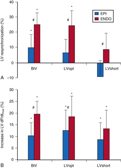
Figure 20-1 Acute hemodynamics of epicardial and endocardial CRT.
(Data from Van Deuren C, van Geldorp IE, Rademakers LM, et al. Endocardial left ventricular pacing improves cardiac resynchronization therapy in canine LBBB hearts. Circ Arrhythm Electrophysiol 2:580-587, 2009.)
Randomized clinical trials on cardiac resynchronization therapy (CRT) have demonstrated its clinical benefits. The acute hemodynamic response to CRT in patients with nonischemic dilated cardiomyopathy depends on the pacing site, with major interindividual and intraindividual variations. In 35 patients with heart failure of nonischemic etiology referred for CRT implantation, the acute hemodynamic response to DDD-LV pacing was systematically assessed at 11 predetermined LV pacing sites. Pacing at the endocardial LV site with the best hemodynamic response doubled the increase in dP/dtmax compared to epicardial coronary sinus pacing6 (Fig. 20-2). CRT with endocardial LV pacing maximizes hemodynamic benefit and may be associated with fewer nonresponders.
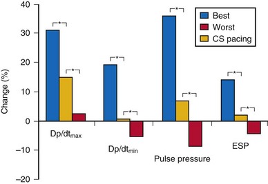
Figure 20-2 Acute hemodynamic changes of DDD-LV pacing.
(Data from Derval N, Steendijk P, Gula LJ, et al. Optimizing hemodynamics in heart failure patients by systematic screening of left ventricular pacing sites: the lateral left ventricular wall and the coronary sinus are rarely the best sites. J Am Coll Cardiol 55:566-575, 2010.)
In a retrospective study comparing chronic epicardial and endocardial pacing, 23 patients with severe heart failure and wide QRS were implanted with CRT devices. Fifteen patients underwent conventional epicardial LV pacing, and eight underwent endocardial LV pacing by atrial transeptal approach because of unfavorable coronary sinus anatomy. Six months after implant, echocardiography and Doppler tissue imaging were performed during right ventricular (RV) and biventricular (BiV) pacing to evaluate LV function, LV wall velocities, and regional electromechanical delay. The septal wall (21.3% vs. 11%) and lateral wall (54% vs. 41%) electromechanical delay was reduced more by endocardial than epicardial CRT compared with RV pacing.7 Endocardial LV pacing improves LV function better than epicardial pacing when measured by standard echocardiographic parameters such as aortic and mitral time-velocity integral (40% vs. 2%) and lateral LV wall systolic motion (31% vs. 14%).7 Endocardial CRT appears to provide more homogeneous intraventricular resynchronization than epicardial CRT and is associated with better LV filling and systolic performance.
Cardiac resynchronization therapy with multisite LV stimulation has been associated with better LV remodeling and a higher left ventricular ejection fraction (LVEF) than conventional BiV stimulation.8 Forty patients with permanent atrial fibrillation undergoing implantation of CRT device were enrolled in a multicenter randomized single-blind crossover study. Each patient had one lead implanted in the right ventricle and two LV leads implanted in two separate coronary veins. Echocardiographic parameter of resynchronization, reverse remodeling, quality of life, and 6-minute walking distance with triple-site (one RV and two LV) versus dual-site (one RV and one LV) stimulation were compared. Triple-site stimulation was associated with a higher LVEF and smaller LV end-systolic volume and diameter.
 Totally Self-Contained Intracardiac Pacemaker
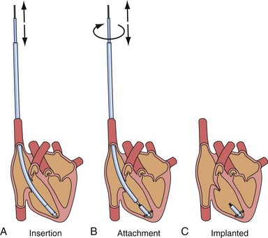
After the first clinical use of implantable pacing system in 1960, a totally self-contained leadless intracardiac pacemaker had been developed as a new concept of pacing technology. The intracardiac pacemaker was as small as a capsule 8 mm in diameter and 18 mm long, with integral electrodes and an attachment mechanism.9 It was small enough to be implanted entirely within the heart when delivered with a catheter guided by a transvenous sheath (Fig. 20-3). The attachment mechanism consisted of radially directed spiral barbs, with the stimulation electrodes located away from the attachment site. In an animal study of three dogs implanted with the prototype of this “capsule” intracardiac pacemaker, after several weeks of implant, the stimulation threshold was stable and less than 1 microjoule per pulse. The first functioning investigational model of the intracardiac pacemaker used a mercury battery as the power source for asynchronous electronic pacing. The system was implanted in a dog with induced heart block and provided asynchronous pacing for 66 days with no complications, because the capsule was in the right ventricle.
Chemical batteries, biologic fuel, kinetic energy, and nuclear-powered energy have been evaluated for incorporation into the capsule intracardiac pacemaker as power sources. Betacel, a family of beta-voltaic nuclear batteries (Douglas Laboratories, McDonnell-Douglas Astronautics, St. Louis) had been developed and incorporated into the first nuclear-powered intracardiac pacemaker.9 The investigational system had been implanted in a dog for asynchronous pacing at 100 beats per minute (bpm) to demonstrate the feasibility of this pacing technology. It was once thought that such technology might enable the battery life of a pacemaker to be extended to several decades. However, results of safety and feasibility on further testing were not reported.
Kinetic Energy
Many concepts have been patented for the development of a leadless pacing system. More than a decade ago, the automatic energy-generating system for quartz watches had been used as a leadless pacemaker power source in an experimental animal model.10 A mechano-electrical energy conversion system developed for quartz watches that converted kinetic energy into electrical energy was used as the power source of a commercially available pulse generator circuit and directly sutured on the epicardial surface of the canine heart. After a full charge, adequate energy was generated for continuous overdrive pacing of the heart for 60 minutes. The stroke motion of the myocardium generated pulses of energy that were stored in a capacitor. The charging and discharging results suggested that the automatic power-generating system might supply enough energy for use in a cardiac pacemaker. It was thought that this might be developed into a button-type cardiac pacemaker to be implanted by a thoracoscopic procedure.
Acoustic (Ultrasound) Energy
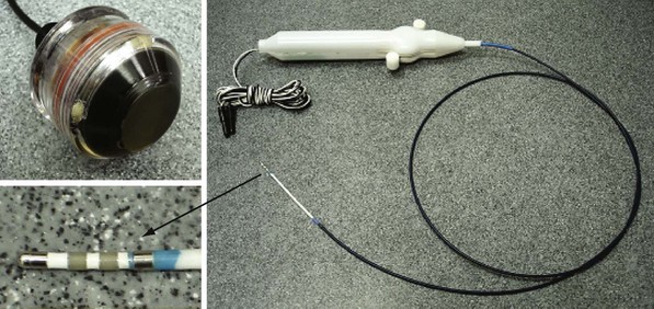
The next development in alternative energy sources for pacing to replace the pacing lead was the use of ultrasound (ultrasonic, acoustic) energy. The use of ultrasound-mediated energy to drive a remotely positioned electrode for direct myocardial stimulation was first reported in 2006.11 This new technology uses the mechano-electrical properties of piezoelectric materials for transformation of energy. The experimental setup used in the acute study included an ultrasound-transmitting transducer connected to an ultrasound generator and a steerable bipolar electrophysiology (EP) catheter incorporating a receiver-electrode near the distal end (Fig. 20-4). Ultrasound energy was amplitude adjusted and transmitted at about 330 kHz. The low frequency used in this application enables better tissue penetration. Ultrasound pulses generated from the transmitting transducer travel through the chest wall to reach the receiver-electrode, with circuitry to transform the pulses into electrical energy for myocardial stimulation.
The feasibility and safety of this novel technology was first demonstrated acutely in animals.11 In the acute safety study, histologic examination was performed in pigs exposed to continuous ultrasound transmission from the investigational system for 2 hours. No mechanical or thermal biologic effect was identified in the sacrificed animals. In the acute feasibility study, the receiver-electrode incorporated into a transvascular catheter was selectively positioned and in contact with various porcine heart chambers. Ultrasound energy was then transmitted from the external transducer placed on the chest wall through the chest to reach the receiver. Acoustic energy was converted to electrical energy, delivered from the receiver-electrode in contact with the myocardium for pacing stimulation. Proximal connections on the EP catheter allowed either direct electrical pacing using a pacing system analyzer (PCA) or monitoring of the receiver output during ultrasound-mediated pacing. The catheter itself was not directly involved in or required for ultrasound-mediated pacing. The acute porcine study demonstrated feasibility of leadless ultrasound-mediated pacing in five animals at 30 select sites in the right atrium, right ventricle, left ventricle, and simultaneously in both left and right ventricles.
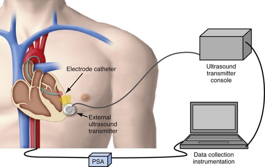
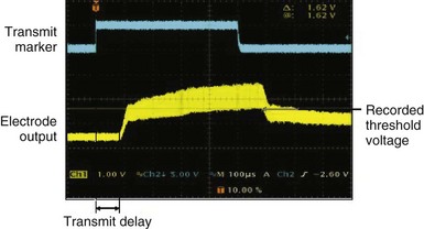
After the animal experiments, an acute human study demonstrated for the first time that the transfer of energy from an external source to stimulate the heart was feasible without a pacing lead.12 The experimental setup was similar to that used in the animal study. A steerable EP catheter with the receiver-electrode incorporated near the distal end was used for introduction into a cardiac chamber and selective positioning at the endocardial pacing location. An external transmitter connected to an ultrasound generator was positioned on the anterior chest wall, and ultrasound gel was used for coupling (Fig. 20-5). The 12 male and 12 female patients age 48 ± 12 years and weighing 75.2 ± 15.7 kg (range, 50-116 kg) were evaluated during or after completion of clinical EP procedures. One patient each had a history of aortic regurgitation, hypertrophic cardiomyopathy, heart failure (HF), hypertension, coronary artery disease, and cerebrovascular accident (stroke). In the HF patient, preexisting AV conduction abnormality was present, and a dual-chamber pacemaker (Philos, Biotronik) had been implanted. No other cardiovascular condition was present in 18 patients. A total of 82 sites were evaluated with the investigational pacing system; two sites were excluded because electrical pacing capture was inconsistent. Of the 80 sites analyzed, 12 were in the right atrium, 35 in the right ventricle, 31 in the left ventricle, and two were LV sites accessed epicardially from a coronary vein. A mean of 3.3 and range of 2-6 sites were evaluated per patient. Electrical and ultrasound-mediated pacing was performed at 460 to 600–msec pacing cycle length and 0.5-msec pulse width. Ultrasound was transmitted at a mean frequency of 350 ± 25 kHz (range, 313-385 kHz). Ultrasound-mediated pacing was successful at all 80 sites, with consistent pacing capture achieved at 77 sites. Beat-to-beat variation in the receiver-electrode output voltage during pacing ranged from 1.04 ± 0.67 V to 2.16 ± 1.10 V. The ultrasound-mediated pacing threshold, attempted at 59 sites in 18 patients, was 1.01 ± 0.64 V. The electrical pacing threshold, obtained at 70 sites in 21 patients, was 1.60 ± 1.12 mA. Assuming a tissue impedance of 605 ohms, the electrical pacing threshold was 0.97 ± 0.67 mA, similar to the ultrasound-mediated pacing threshold (Fig. 20-6). The mechanical index (MI) at the site during ultrasound-mediated pacing was 0.51 ± 0.31 MI (range, 0.12-1.50 MI). In the 18 patients with calculated ultrasound-mediated pacing thresholds, MI at the site was 0.45 ± 0.30. The mean electrical output energy per pacing pulse was 2.68 ± 3.04 microjoules (µJ), while the mean ultrasound energy burst was 12.86 ± 15.70 millijoules (mJ). The transmitter to receiver distance was 11.3 ± 3.2 cm. Ultrasound-mediated pacing was achieved at all 80 sites with consistent capture at 77 sites. No adverse event was related to ultrasound-mediated pacing. No patient experienced discomfort during pacing.
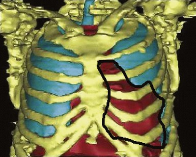
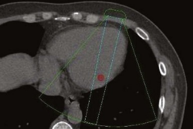
A major target of this novel technology is CRT. Leadless pacing with ultrasound-mediated energy was also tested in HF patients.13 Ten patients with advanced HF and LVEF ≤35% were studied. With the same experimental setup, a receiver-electrode to deliver ultrasound-mediated pacing was positioned endocardially in the lateral or posterior LV wall after a clinically indicated left-sided heart catheterization. Ultrasound-mediated pacing thresholds were determined. The acoustic windows on the chest wall that allowed consistent capture were determined with the patient lying supine, titled 30 degrees leftward, 30 degrees rightward, and 30 degrees upward. The acoustic windows were also determined with computed tomography (CT) and transthoracic echocardiography. Three-dimensional thoracic CT reconstruction was obtained with the patient in supine position during end-inspiration and right lateral position during both end-inspiration and end-expiration. The area on the chest wall mapping the transmission path to the heart without any intervening lung tissue was defined as the CT-determined acoustic window (Fig. 20-7). The receiver-electrode location and the standard transmitter location were simulated on the 3D reconstruction, and the horizontal and vertical movements of the receiver relative to the transmitter were determined in all three scanning conditions. Transthoracic echocardiography using a commercially available ultrasound imaging system and a vascular transducer operating at frequency range of 3-11 MHz was performed to determine the echocardiographic acoustic window. The measurement was acquired with the patient lying in multiple positions, as with those tested during ultrasound-mediated pacing. The echocardiographic acoustic window on the chest wall that allowed clear visualization of the near-field endocardium was measured.
Implantable Leadless Pacing System
The implantable electrode is an ultrasound energy converter in a titanium can 1 cm long and 2.67 mm in diameter, with an active-fixation anchor mechanism with five active barbs (Fig. 20-9). The tip of the anchor functions as the cathode while the body functions as the anode. Preliminary short-term results (6-95 days) on use of the endocardial LV pacing system (WiCS, EBR Systems, Sunnyvale, Calif) on eight goats showed no dislodgement, thrombus formation, or embolization.14 The pacing electrodes were fully endothelialized at 90 days, with a fibrous capsule of 0.36-mm mean thickness and mean implant depth of 2.65 mm into the endocardium.
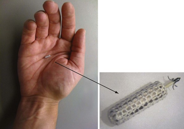
Figure 20-9 Implantable leadless intracardiac electrode.
An ultrasound energy converter with five active barbs for anchoring.
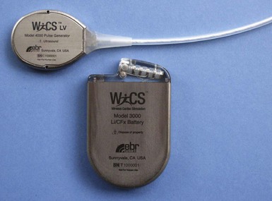
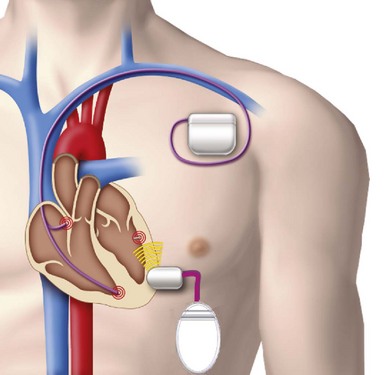
The transmitter (13 cc, 25 g) will be implanted subcutaneously in the acoustic window of the chest wall while the cable is being tunneled, and the battery (42 cc, 90 g) implanted in the abdominal pocket. The receiver and transmitter are programmed to operate at the same frequency of ultrasound pulses. The ultrasound beam will be optimized and focused onto the receiver-electrode to improve the efficacy of energy transfer (Fig. 20-10). The estimated device longevity will need to be comparable to that of a conventional pacemaker to make it commercially viable. The acoustic window suitable for implant on the patient’s chest wall can be localized preoperatively by conventional echocardiography, a convenient method that can predict efficient ultrasound transmission for leadless pacing.13,15
A novel method was developed to distinguish right ventricular, right atrial, or left ventricular pacing output to enable the leadless system to provide LV pacing synchronized to the RV pacing of a co-implanted pacemaker or defibrillator to provide CRT16 (Fig. 20-11). Addition of the leadless LV stimulation system to a conventional dual-chamber pacemaker or defibrillator for CRT is the current state of development and clinical research.
Although this leadless technology provides thus far the most developed system, many will doubt the long-term safety and feasibility of continuous ultrasound stimulation (Box 20-1).17,18 Although the lack of effect of short-term ultrasound-mediated pacing has been shown histologically in animal experiments, tissue injury secondary to heating with continuous exposure is theoretically possible. A novel method developed for calibration of acoustic energy transfer in the wireless pacing system may improve its long-term safety.19 Interference from ubiquitous environmental sources may also be hazardous, although precise formatting and fine-tuning of the device can be done to minimize this, which is certainly a major safety issue that requires extensive evaluation. A user-friendly delivery system with a reliable anchoring mechanism is essential for a safe and optimal implantation. Regarding the risk of infection, the receiver-electrode is small and embedded in the endocardium, and complete endothelialization was seen in animal studies. The risk of infection should be low and comparable to that of implanting a coronary stent or an atrial septal defect–occluding device.
Box 20-1
Challenges in Development of Leadless Pacing Technology with Ultrasound Energy
In addition to energy delivery, transmission of a sensed signal is an important function of a pacing lead. There is little information on how the sensing circuit of the stand-alone leadless pacemaker will operate. The sensing mechanism used in the investigational subcutaneous defibrillator may provide some insight.20 There are certainly many challenging issues to be resolved before this concept can be turned into a commercially available implantable pacing device.
Induction Technology
Besides kinetic and acoustic energy sources, electric pulses transformed from an alternating magnetic field have recently been tested in a porcine model for leadless cardiac stimulation.21 The system consists of two components, a subcutaneous transmitter unit and an endocardial receiver unit. The subcutaneous primary coil generates an alternating magnetic field, which is converted by the secondary coil inside the heart to a voltage pulse for pacing stimulation. In the porcine experiment described, an alternating magnetic field of approximately 0.5 mT was generated by the transmitter unit in a distance of 3 cm. Voltage pulses with a duration of 0.4 msec and voltage amplitude of 0.6 to 1.0 V were generated. Continuous stimulation of the porcine heart was demonstrated for 30 minutes.
 Biologic Pacemaker
Genetically engineered pacemakers may become a viable alternative to implantable electronic devices for the treatment of bradyarrhythmias in the future (see Chapter 7). Gene-based approaches involve beta-2 adrenergic receptor (β2-AR),22 repolarizing current (IK1),23,24 and funny current (If),25–28 as prime targets for gene transfer that allow nonpacemaker cardiomyocytes to generate rhythmic action potentials such as the genuine, electrically active nodal pacemaker cells. The earliest attempt in enhancing cardiac chronotropy (but not inducing pacemaker activity) was made with transient, overexpressing β2-ARs in the right atrium of swine.22 Because the pacemaker activity of the native sinoatrial (SA) node is modulated by the autonomous nervous system, β2-AR regulates cardiomyocyte chronotropic responses through a G protein and cAMP-mediated pathway. Stimulation of β2-AR increases the If in cardiomyocytes and subsequently leads to an increased rate of depolarization. Upregulation of β2-AR by overexpressing the cloned receptor has been shown to increase the response of the heart rate to adrenergic stimulation. Although If is most abundant in the SA node, overexpression of wild-type hyperpolarization-activated cyclic nucleotide (HCN)—modulated channel alone does not suffice to induce automaticity in quiescent adult LV cells.29,30 Unlike SA nodal cells, adult atrial and ventricular cells are normally electrically quiescent because of the intense expression of the cardiac inward-rectifier K+ current, IK1 (encoded by the Kir2 gene family), that stabilizes a negative resting membrane potential, about −80mV, and thus suppresses excitability or any latent spontaneous pacemaker activity. By contrast, IK1 is virtually absent in the SA nodal cells. In fact, it has been convincingly demonstrated that latent pacemaker activity of normally quiescent cardiomyocytes can be unleashed to produce spontaneous firing activity by genetic inhibition of Kir2-encoded IK1, although the induced firing is approximately threefold slower than normal.23,24 In addition, the inability to induce automaticity by overexpression of wild-type HCN channels may also be related to the complex molecular identity of endogenous If.
Instead, employing protein-engineering technology to create mutant HCN channels with more favorable biophysical properties, two engineered HCN channels, mE324A25,26 and HCN 235-7,27,28 have been reported to reduce the pacemaker dependence in a large, animal bradycardia model. Apart from conversion of myocytes into pacemaker cells, other strategies include stem cell transplantation.29 Unresolved issues include longevity and stability of pacemaker genes, as well as limitations in adenoviral and stem cell therapy. Research in this area will provide insight on whether a biologic pacemaker will become clinical reality and outperform electronic pacemaker in terms of safety, reliability, and longevity.
 Conclusion
1 Baddour LM, Epstein AE, Erickson CC. Update on cardiovascular implantable electronic device infections and their management: a scientific statement from the American Heart Association. Circulation. 2010;121:458-477.
2 Borek PP, Wilkoff BL. Pacemaker and ICD leads: strategies for long-term management. J Interv Card Electrophysiol. 2008;23:59-72.
3 Bax JJ, Abraham T, Barold SS, et al. Cardiac resynchronization therapy. Part 2. Issues during and after device implantation and unresolved questions. J Am Coll Cardiol. 2005;46:2168-2184.
4 Barold SS, Herwerg B. Pacing in heart failure: how many leads and where? Heart. 2008;94:10-13.
5 Van Deuren C, van Geldorp IE, Rademakers LM, et al. Endocardial left ventricular pacing improves cardiac resynchronization therapy in canine LBBB hearts. Circ Arrhythm Electrophysiol. 2009;2:580-587.
6 Derval N, Steendijk P, Gula LJ, et al. Optimizing hemodynamics in heart failure patients by systematic screening of left ventricular pacing sites: the lateral left ventricular wall and the coronary sinus are rarely the best sites. J Am Coll Cardiol. 2010;55:566-575.
7 Garrigue S, Jais P, Guillaume E, et al. Comparison of chronic biventricular pacing between epicardial and endocardial left ventricular stimulation using Doppler tissue imaging in patients with heart failure. Am J Cardiol. 2001;88:858-862.
8 Leclercq C, Gadler F, Kranig W, et al. A randomized comparison of triple-site versus dual-site ventricular stimulation in patients with congestive heart failure. J Am Coll Cardiol. 2008;51:1455-1462.
9 Spickler JW, Rasor NS, Kezdi P, et al. Totally self-contained intracardiac pacemaker. J Electrocardiol. 1970;3:325-331.
10 Goto H, Sugiura T, Harada Y, et al. Feasibility of using the automatic generating system for quartz watches as a leadless pacemaker power source. Med Biol Eng Comput. 1999;37:377-380.
11 Echt DS, Cowan MW, Riley RE, et al. Feasibility and safety of a novel technology for pacing without leads. Heart Rhythm. 2006;3:1202-1206.
12 Lee KL, Lau CP, Tse HF, et al. First human demonstration of cardiac stimulation with transcutaneous ultrasound energy delivery: Implications for wireless pacing with implantable devices. J Am Coll Cardiol. 2007;50:877-883.
13 Lee KL, Tse HF, Echt DS, et al. Temporary leadless pacing in heart failure patients with ultrasound-mediated stimulation energy and effects on acoustic window. Heart Rhythm. 2009;6:742-748.
14 Echt DS, Moore D, Cowan M, et al. Chronic implantation of leadless pacing electrodes in the left ventricle of a goat model [abstract]. Heart Rhythm. 2010;7(5 suppl):451-452.
15 Yeh DD, Fu DK, Kwan D, et al. Acoustic window for ultrasound-mediated leadless cardiac pacing [abstract]. Heart Rhythm. 2009;6(5 suppl):315-316.
16 Liem LB, Mead RH, Fowler R, et al. A novel method for synchronizing leadless pacing to a co-implanted pacing system [abstract]. Heart Rhythm. 2010;7(5 suppl):309.
17 Sweeney MO. In a footnote, at least. Heart Rhythm. 2006;3:1207-1209.
18 Benditt DG, Goldstein M, Belalcazar A. The leadless ultrasound pacemaker: a sound idea? Heart Rhythm. 2009;6:749-751.
19 Willis NP, Brisken A, Echt DS, et al. Novel method for calibration of acoustic energy transfer in a wireless pacing system [abstract]. Heart Rhythm. 2010;7(5 suppl):373.
20 Bardy GH, Smith WM, Hood MA, et al. An entirely subcutaneous implantable cardioverter-defibrillator. N Engl J Med. 2010;363:36-44.
21 Wieneke H, Konorza T, Erbel R, et al. Leadless pacing in the heart using induction technology: a feasibility study. Pacing Clin Eletrophysiol. 2009;32:177-183.
22 Edelberg JM, Huang DT, Josephson ME, Rosenberg RD. Molecular enhancement of porcine cardiac chronotropy. Heart. 2001;86(5):559-562.
23 Miake J, Marban E, Nuss HB. Gene therapy: Biological pacemaker created by gene transfer. Nature. 2002;419:132-133.
24 Miake J, Marban E, Nuss HB. Functional role of inward rectifier current in heart probed by Kir2.1 overexpression and dominant-negative suppression. J Clin Invest. 2003;111:1529-1536.
25 Bucchi A, Plotnikov AN, Shlapakova I, et al. Wild-type and mutant HCN channels in a tandem biological-electronic cardiac pacemaker. Circulation. 2006;114(10):992-999.
26 Rosen MR, Brink PR, Cohen IS, et al. Genes, stems cells, and biological pacemakers. Cardiovasc Res. 2004;64:12-23.
27 Xue T, Siu CW, Lieu DK, et al. Mechanistic role of I(f) revealed by induction of ventricular automaticity by somatic gene transfer of gating-engineered pacemaker (HCN) channels. Circulation. 2007;115:1839-1850.
28 Tse HF, Xue T, Lau CP, et al. Bioartificial sinus node constructed via in vivo gene transfer of an engineered pacemaker HCN channel reduces the dependence on electronic pacemaker in a sick-sinus syndrome model. Circulation. 2006;114:1000-1011.
29 Plotnikov AN, Shlapakova I, Szabolcs MJ, et al. Xenografted adult human mesenchymal stem cells provide a platform for sustained biological pacemaker function in canine heart. Circulation. 2007;116:706-713.
30 Qu J, Barbuti A, Protas L, et al. HCN2 overexpression in newborn and adult ventricular myocytes: distinct effects on gating and excitability. Circ Res. 2001;89:E8-E14.
